CN210139320U - Reciprocating type conveying and positioning equipment - Google Patents
Reciprocating type conveying and positioning equipment Download PDFInfo
- Publication number
- CN210139320U CN210139320U CN201920561943.XU CN201920561943U CN210139320U CN 210139320 U CN210139320 U CN 210139320U CN 201920561943 U CN201920561943 U CN 201920561943U CN 210139320 U CN210139320 U CN 210139320U
- Authority
- CN
- China
- Prior art keywords
- conveying
- component
- lifting
- guide
- driving
- Prior art date
- Legal status (The legal status is an assumption and is not a legal conclusion. Google has not performed a legal analysis and makes no representation as to the accuracy of the status listed.)
- Active
Links
Images


Abstract
The utility model discloses a reciprocating type conveying and positioning device, which is used in the technical field of production line conveying devices and comprises a plurality of tool fixtures which are arranged in sequence according to processing procedures; the conveying guide component sequentially passes through the work fixtures; the conveying unit comprises a conveying component, a lifting component and a lifting driving component, wherein the lifting driving component can drive the lifting component to rise or fall on the conveying component, and a workpiece positioning structure is arranged on the lifting component; and the driving unit is connected with the conveying unit and can drive the conveying unit to reciprocate along the conveying guide component so as to transmit the workpiece among different tool fixtures. According to the technical scheme, the equipment mechanism is simplified, the mechanical structure is simplified, the manufacturing cost is reduced, the occupied space is saved, and the installation and maintenance are convenient.
Description
Technical Field
The utility model is used for production line conveying equipment technical field especially relates to a reciprocating type conveying positioning device.
Background
With the continuous development of the automobile manufacturing industry, the automobile production and manufacturing become intelligent and lean day by day. A production mode with low cost, high efficiency and high yield is more and more favored by the market. In the production and manufacturing process of automobiles, reciprocating type conveying and positioning equipment is one of common general equipment in production lines, and the main function of the equipment is to orderly transmit and position workpieces among stations, so that the workpieces can be welded, glued, riveted and the like. The common reciprocating type conveying and positioning equipment in the market at present has the advantages of higher manufacturing cost, longer supply period, complex structural form, larger occupied space and inconvenience in installation and maintenance.
SUMMERY OF THE UTILITY MODEL
An object of the utility model is to solve one of the technical problem that exists among the prior art at least, provide a reciprocating type transport positioning device, it has simplified mechanical structure, has reduced manufacturing cost, practices thrift occupation space, is convenient for install and maintain.
The utility model provides a technical scheme that its technical problem adopted is: reciprocating conveying and positioning device comprises
The plurality of tool fixtures are sequentially arranged according to the machining procedures;
the conveying guide component sequentially passes through the work fixtures;
the conveying unit comprises a conveying component, a lifting component and a lifting driving component, wherein the lifting driving component can drive the lifting component to rise or fall on the conveying component, and a workpiece positioning structure is arranged on the lifting component; and
and the driving unit is connected with the conveying unit and can drive the conveying unit to reciprocate along the conveying guide component so as to transmit the workpiece among different tool fixtures.
Preferably, the conveying component is provided with a cylinder connecting component and a lifting guide rod for guiding the lifting component to lift, the lifting driving component comprises a first cylinder which is inversely installed on the lifting component, a cylinder rod of the first cylinder is connected with the cylinder connecting component, the lifting component is provided with a supporting component, and the supporting component is provided with a workpiece positioning structure.
Preferably, the lifting part is provided with a lifting guider, the lifting guider comprises a mounting sleeve and a shaft sleeve arranged in the mounting sleeve, the lifting guide rod penetrates through the shaft sleeve, and the lifting guide rod is provided with a limiting part.
Preferably, the workpiece positioning structure comprises a positioning pin and an inner inclined plane U-shaped block, and the positioning pin and the inner inclined plane U-shaped block are both mounted on the supporting component through adjustable mounting seats.
Preferably, the conveying guide component comprises a guide rail, and a first guide wheel matched with the guide rail is arranged on the conveying component.
Preferably, the conveying device further comprises a rack arranged in parallel with the guide rail, the driving unit comprises a driving platform, a transmission driving part and a gear, a fourth guide wheel matched with the guide rail is arranged on the driving platform, the driving platform is connected with the conveying part, the transmission driving part is arranged on the driving platform, and the gear is arranged at the output end of the transmission driving part and meshed with the rack.
Preferably, the conveying device further comprises a conveying unit positioning mechanism, the conveying unit positioning mechanism comprises a bolt, a second air cylinder and a fixed guide wheel assembly, the fixed guide wheel assembly is arranged on the conveying part, the fixed guide wheel assembly comprises a second guide wheel and a third guide wheel, a bolt gap is formed between the second guide wheel and the third guide wheel, and the second air cylinder can drive the bolt to be embedded into or separated from the bolt gap.
Preferably, the number of the conveying units is one less than that of the tool fixtures, the conveying units are sequentially connected through connecting pieces in the transmission direction, and the driving unit is arranged between the two adjacent conveying units and is connected with the two adjacent conveying units through the connecting pieces at two ends.
Preferably, the connecting member includes a connecting rod, and both ends of the connecting rod are provided with hinges for connecting the conveying unit or the driving unit.
Preferably, the tooling fixture comprises a base frame, an adjustable mounting foot seat and a fixture unit, the adjustable mounting foot seat is arranged at the bottom of the base frame, the fixture unit is arranged on the base frame, the base frames of the tooling fixture are sequentially connected through a connecting frame, and the conveying guide component is arranged along the base frame and the connecting frame.
One of the above technical solutions has at least one of the following advantages or beneficial effects: the plurality of tool fixtures are sequentially arranged according to a machining procedure to form a whole or part of a production line, wherein the tool fixtures are used for positioning workpieces at each station, the conveying guide component provides a walking track for the conveying unit and the driving unit, the conveying unit is used for realizing ordered conveying of the workpieces among the stations, and the lifting component of the conveying unit is used for lifting the workpieces so as to lift the workpieces from the tool fixtures at one station and convey the workpieces to the next station, and then the workpieces fall down at the next station and are placed on the tool fixtures at the station. According to the technical scheme, the equipment mechanism is simplified, the mechanical structure is simplified, the manufacturing cost is reduced, the occupied space is saved, and the installation and maintenance are convenient.
Drawings
The present invention will be further explained with reference to the accompanying drawings:
fig. 1 is a schematic structural diagram of an embodiment of the present invention;
FIG. 2 is a schematic view of the structure of the base frame, the connecting frame, and the conveying guide member of FIG. 1 according to one embodiment;
FIG. 3 is a schematic diagram of the structure of a conveying unit and a driving unit of the embodiment shown in FIG. 1;
FIG. 4 is a schematic diagram of the structure of the driving unit of FIG. 1 according to one embodiment;
FIG. 5 is a schematic diagram of the construction of one embodiment of the delivery unit shown in FIG. 1;
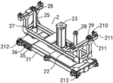
FIG. 6 is a schematic view of the transport component of one embodiment shown in FIG. 1;
FIG. 7 is a schematic diagram of the construction of one embodiment of the lifting member shown in FIG. 1;
fig. 8 is a schematic structural view of a positioning mechanism of the conveying unit according to one embodiment shown in fig. 1.
Detailed Description
This section will describe in detail the embodiments of the present invention, preferred embodiments of the present invention are shown in the attached drawings, which are used to supplement the description of the text part of the specification with figures, so that one can intuitively and vividly understand each technical feature and the whole technical solution of the present invention, but they cannot be understood as the limitation of the protection scope of the present invention.
In the present invention, if there is a description of directions (up, down, left, right, front and back), it is only for convenience of description of the technical solution of the present invention, and it is not intended to indicate or imply that the technical features indicated must have a specific orientation, be constructed and operated in a specific orientation, and thus should not be construed as limiting the present invention.
In the present invention, "a plurality" means one or more, "a plurality" means two or more, "more than", "less than", "more than", and the like, which means that the number is not included; the terms "above", "below", "within" and the like are to be understood as including the number. In the description of the present invention, if there is any description of "first" and "second" only for the purpose of distinguishing technical features, it is not to be understood as indicating or implying relative importance or implicitly indicating the number of indicated technical features or implicitly indicating the precedence of the indicated technical features.
In the present invention, unless otherwise explicitly defined, the terms "set," "mounted," "connected," and the like are to be understood in a broad sense, and may be directly connected or indirectly connected through an intermediate medium, for example; can be fixedly connected, can also be detachably connected and can also be integrally formed; may be mechanically coupled, may be electrically coupled or may be capable of communicating with each other; either as communication within the two elements or as an interactive relationship of the two elements. The technical skill in the art can reasonably determine the specific meaning of the above words in the present invention by combining the specific contents of the technical solution.
Referring to fig. 1, an embodiment of the present invention provides a reciprocating conveying positioning apparatus, which includes
The plurality of the tool fixtures 5 are sequentially arranged according to the processing procedures to form all or part of the production line, the number of modules of the tool fixtures 5 can be arranged according to actual requirements, and the tool fixtures 5 are used for positioning workpieces at each station so as to enable the workpieces to complete the production procedures of welding, gluing, riveting and the like;
the conveying guide component 1 sequentially passes through the work fixtures 5 and provides a walking track for the conveying unit 2 and the driving unit;
the conveying unit 2 comprises a conveying component 21, a lifting component 22 and a lifting driving component, the lifting driving component can drive the lifting component 22 to lift up or fall down on the conveying component 21, a workpiece positioning structure is arranged on the lifting component 22, the conveying unit 2 is used for realizing ordered transmission of workpieces among stations, the lifting component 22 of the conveying unit 2 is used for lifting the workpieces so as to lift the workpieces from the tooling fixture 5 of one station and convey the workpieces to the next station, and then the workpieces fall down at the next station and are placed on the tooling fixture 5 of the station; and
and the driving unit 4 is connected with the conveying unit 2 and can drive the conveying unit 2 to reciprocate along the conveying guide component 1 so as to transmit the workpieces among different tool fixtures 5.
According to the technical scheme, the equipment mechanism is simplified, the mechanical structure is simplified, the manufacturing cost is reduced, the occupied space is saved, and the installation and maintenance are convenient.
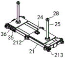
Referring to fig. 5-7, the conveying member 21 is provided with an air cylinder connecting member 24 and a lifting guide rod 25 for guiding the lifting member 22 to lift, the lifting driving member includes a first air cylinder 23 inversely installed on the lifting member 22, an air cylinder rod of the first air cylinder 23 is connected with the air cylinder connecting member 24, the first air cylinder 23 provides power for the lifting action of the conveying unit 2, the lifting member 22 is provided with a supporting member 26, and the supporting member 26 is provided with a workpiece positioning structure for supporting and positioning a workpiece conveyed thereon. The lifting guide rod 25 is used for ensuring the smooth movement of the lifting member 22 during the lifting process. Wherein, the mode of first cylinder 23 with the combination of lift guide bar 25 has simplified mechanical structure greatly, has reduced manufacturing cost, adopts the cylinder to invert the structure of using in addition, can reduce the whole height of equipment, and manual inspection and maintenance are more convenient. The technical scheme has the advantages of simple structure, economy and practicality, reduction of manufacturing cost, occupation space saving and convenience in installation and maintenance.
In some embodiments, one or more lifting guide rods 25 are provided, and preferably, referring to fig. 5 and 6, the lifting guide rods 25 include a first lifting guide rod and a second lifting guide rod, the first cylinder 23 is provided between the first lifting guide rod and the second lifting guide rod, the structural balance is better, and the first lifting guide rod and the second lifting guide rod cooperate with one cylinder thereof to jointly ensure that the lifting component 22 operates stably during lifting.
In some embodiments, the lifting member 22 is provided with a guide hole, a guide groove, etc. engaged with the lifting guide rod 25; in some embodiments, referring to fig. 5, the lifting member 22 is provided with a lifting guide 27, the lifting guide 27 includes a mounting sleeve and a bushing disposed in the mounting sleeve, the bushing is preferably a self-lubricating bushing, the lifting guide rod 25 passes through the bushing, and the lifting guide rod 25 is provided with a limiting member 28 for controlling the lifting stroke of the lifting member 22.
In some embodiments, the supporting members 26 are provided with one or more supporting members for providing stable support for a workpiece such as a vehicle body member, and preferably, referring to fig. 7, the supporting members 26 include a first supporting member and a second supporting member, which are respectively provided at both ends of the lifting member 22, and the first supporting member and the second supporting member are lifted upward to a height at least higher than the height of the lifting guide rod 25 and the first cylinder 23.
The workpiece positioning structure is used for positioning a workpiece on the supporting part 26, in some embodiments, the workpiece positioning structure adopts a clamping groove, a buckle, a clamp and the like, as preferable results, referring to fig. 5 and 7, the workpiece positioning structure includes a positioning pin 29 and an inner inclined plane U-shaped block 210, the inclined plane U-shaped block 210 is respectively arranged at four corners of the top of the supporting part 26 and used for guiding the workpiece to accurately position, the positioning pin 29 and the inner inclined plane U-shaped block 210 are both arranged on the supporting part 26 through an adjustable mounting seat 211, and a plurality of adjusting bolts capable of adjusting the inner inclined plane U-shaped block 210 and the positioning pin 29 are arranged on the adjustable mounting seat 211, so that the workpiece positioning structure can be accurately aligned with structures such as a pin.
In some embodiments, the conveyance guide member 1 may employ a conveyance roller.
In certain embodiments, the transport guide member 1 comprises a guide rail. The conveying component 21 is matched with the guide rail through a sliding block or a guide wheel, preferably, referring to fig. 5 and 6, a first guide wheel matched with the guide rail is arranged on the conveying component 21, the first guide wheel comprises a first side guide wheel 212 and a first bottom guide wheel 213, and the first side guide wheels 212 are arranged on two sides of the conveying component 21, three on each side. The first bottom guide wheels 213 are provided at the corners of both ends of the conveying member 21.
In some embodiments, the driving unit 4 may drive the rollers by using driving members, and drive the conveying members 21 by friction force of the rollers and the guide rails.
In some embodiments, referring to fig. 1, 3 and 4, the present invention further includes a rack 6 disposed in parallel with the guide rail, the driving unit 4 includes a driving platform 41, a driving member 42 and gears, the driving platform 41 is provided with a fourth guide wheel engaged with the guide rail, the fourth guide wheel includes four second side guide wheels 43 and two second bottom guide wheels 44, the number of the second side guide wheels 43 is four, the four second side guide wheels 43 are respectively mounted at corners of two ends of the driving platform 41, the four second bottom guide wheels 44 are respectively mounted at corners of two ends of the driving platform 41, the driving platform 41 is connected to the conveying member 21, the driving member 42 is disposed on the driving platform 41, and the gears are disposed at an output end of the driving member 42 and engaged with the rack 6. The driving part 42 comprises a motor and a speed reducer and is installed on the driving platform 41 through a mounting seat, and the driving platform 41 is provided with an adjusting block to adjust the gap between a gear and a rack on a shaft of the speed reducer. The drive platform 41 is provided with a lubricating device for adding lubricating oil to the gears on the shaft of the reducer.
In some embodiments, the driving platform 41, the conveying component 21, and the lifting component 22 may adopt a frame assembly, a plate structure, etc., and preferably, referring to fig. 3, 4, and 5, the conveying component 21 and the lifting component 22 are welded by rectangular hollow pipes, reinforcing ribs, and mounting plates, so that the structure is simplified, and the structure has high strength and light weight.
In some embodiments, in order to accurately position the conveying unit 2 in the station, referring to fig. 8, the positioning mechanism 3 for the conveying unit 2 is further included, the positioning mechanism 3 for the conveying unit 2 includes a bolt 31, a second cylinder 32, an angle seat 33, an L-shaped mounting seat 34, and a fixed guide wheel assembly, the angle seat 33 is installed at the side of the guide rail, the L-shaped mounting seat 34 is installed on the angle seat 33, a gasket is arranged between the bolt 31 and the angle seat 33 for adjusting the position, the bolt 31 passes through the L-shaped mounting seat 34 and a self-lubricating bushing and is connected with a cylinder rod of the second cylinder 32, the fixed guide wheel assembly is arranged on the conveying part 21, the fixed guide wheel assembly includes a mounting seat 37, a second guide wheel 35 and a third guide wheel 36, a gap 31 is formed between the second guide wheel 35 and the third guide wheel 36, and the second cylinder 32 can drive the bolt 31 to be inserted into or removed. For use with a fixed guide wheel assembly to secure the conveyor unit 2.
In some embodiments, one or more conveying units 2 are provided, preferably, referring to fig. 1 and 3, the number of the conveying units 2 is one less than that of the tooling fixtures 5, and a plurality of the conveying units 2 are connected in sequence by the connecting piece 214 along the conveying direction. The number of conveyor units 2 may be arranged according to practical requirements. When the conveying units 2 are more than three, the conveying units 2 are uniformly distributed at equal intervals to meet the requirement of switching workpieces among different stations.
In some embodiments, referring to fig. 3, the driving unit 4 is disposed between two adjacent conveying units 2 and is connected to two adjacent conveying units 2 through the connecting members 214 at two ends.
In the above embodiment, the connecting member 214 may be a connecting rod, a connecting shaft, a chain, etc., and preferably, the connecting member includes a connecting rod, and both ends of the connecting rod are provided with hinges for connecting the conveying unit 2 or the driving unit 4.
Referring to fig. 1 and 2, a tooling fixture 5 is of a modular design, the tooling fixture 5 includes a base frame 51, an adjustable mounting base 52 and a fixture unit 53, the base frame 51 is used for mounting the multi-station fixture unit 53 and providing a mounting frame for the conveying guide component 1, the adjustable mounting base 52 is arranged at the bottom of the base frame 51, the adjustable mounting base 52 is mounted on the ground, the fixture unit 53 is arranged on the base frame 51, the fixture unit 53 is composed of a plurality of different connecting pieces and cylinders and is used for positioning vehicle body parts at each station, and the structure and the number of the fixture unit are determined by the processing requirements of the station and the positioning requirements of the vehicle body parts; the base frames 51 of the work fixtures 5 are sequentially connected through the connecting frame 54, and the conveying guide component 1 is arranged along the base frames 51 and the connecting frame 54, so that a walking track is provided for a reciprocating conveying system.
The invention is not limited to the above embodiments, and those skilled in the art can make equivalent modifications or substitutions without departing from the spirit of the invention, and such equivalent modifications or substitutions are included in the scope defined by the claims of the present application.
Claims (10)
1. Reciprocating type conveying positioning equipment which characterized in that: comprises that
The plurality of tool fixtures are sequentially arranged according to the machining procedures;
the conveying guide component sequentially passes through the work fixtures;
the conveying unit comprises a conveying component, a lifting component and a lifting driving component, wherein the lifting driving component can drive the lifting component to rise or fall on the conveying component, and a workpiece positioning structure is arranged on the lifting component; and
and the driving unit is connected with the conveying unit and can drive the conveying unit to reciprocate along the conveying guide component so as to transmit the workpiece among different tool fixtures.
2. The reciprocating transport positioning apparatus of claim 1, wherein: the lifting driving part comprises a first cylinder which is arranged on the lifting part in an inverted mode, a cylinder rod of the first cylinder is connected with the cylinder connecting part, the lifting part is provided with a supporting part, and the supporting part is provided with a workpiece positioning structure.
3. The reciprocating transport positioning apparatus of claim 2, wherein: the lifting guide device is characterized in that a lifting guide device is arranged on the lifting part and comprises an installation sleeve and a shaft sleeve arranged in the installation sleeve, the lifting guide rod penetrates through the shaft sleeve, and a limiting part is arranged on the lifting guide rod.
4. The reciprocating transport positioning apparatus of claim 2, wherein: the workpiece positioning structure comprises a positioning pin and an inner inclined plane U-shaped block, and the positioning pin and the inner inclined plane U-shaped block are both installed on the supporting part through adjustable installation seats.
5. The reciprocating transport positioning apparatus of claim 1, wherein: the conveying guide component comprises a guide rail, and a first guide wheel matched with the guide rail is arranged on the conveying component.
6. The reciprocating transport positioning apparatus of claim 5, wherein: the conveying device is characterized by further comprising a rack arranged in parallel with the guide rail, the driving unit comprises a driving platform, a transmission driving part and a gear, a fourth guide wheel matched with the guide rail is arranged on the driving platform, the driving platform is connected with the conveying part, the transmission driving part is arranged on the driving platform, and the gear is arranged at the output end of the transmission driving part and meshed with the rack.
7. The reciprocating transport positioning apparatus of claim 1, wherein: the conveying unit positioning mechanism comprises a bolt, a second air cylinder and a fixed guide wheel assembly, the fixed guide wheel assembly is arranged on the conveying part and comprises a second guide wheel and a third guide wheel, a bolt gap is formed between the second guide wheel and the third guide wheel, and the second air cylinder can drive the bolt to be embedded into or separated from the bolt gap.
8. The reciprocating transport positioning apparatus of claim 1, wherein: the conveying units are one less than the tool fixtures in number, the conveying units are sequentially connected through connecting pieces in the transmission direction, and the driving units are arranged between the two adjacent conveying units and are connected with the two adjacent conveying units through the connecting pieces at the two ends.
9. The reciprocating transport positioning apparatus of claim 8, wherein: the connecting piece includes the connecting rod, the both ends of connecting rod are equipped with the hinge of connecting conveying unit or drive unit.
10. The reciprocating transport positioning apparatus of claim 1, wherein: the fixture comprises a base frame, an adjustable mounting foot seat and fixture units, wherein the adjustable mounting foot seat is arranged at the bottom of the base frame, the fixture units are arranged on the base frame, the base frame of the fixture is sequentially connected through a connecting frame, and the conveying guide component is arranged along the base frame and the connecting frame.
Priority Applications (1)
| Application Number | Priority Date | Filing Date | Title |
|---|---|---|---|
| CN201920561943.XU CN210139320U (en) | 2019-04-23 | 2019-04-23 | Reciprocating type conveying and positioning equipment |
Applications Claiming Priority (1)
| Application Number | Priority Date | Filing Date | Title |
|---|---|---|---|
| CN201920561943.XU CN210139320U (en) | 2019-04-23 | 2019-04-23 | Reciprocating type conveying and positioning equipment |
Publications (1)
| Publication Number | Publication Date |
|---|---|
| CN210139320U true CN210139320U (en) | 2020-03-13 |
Family
ID=69729450
Family Applications (1)
| Application Number | Title | Priority Date | Filing Date |
|---|---|---|---|
| CN201920561943.XU Active CN210139320U (en) | 2019-04-23 | 2019-04-23 | Reciprocating type conveying and positioning equipment |
Country Status (1)
| Country | Link |
|---|---|
| CN (1) | CN210139320U (en) |
-
2019
- 2019-04-23 CN CN201920561943.XU patent/CN210139320U/en active Active
Similar Documents
| Publication | Publication Date | Title |
|---|---|---|
| CN103449118B (en) | A kind of weld car side wall line conveying mechanism | |
| CN212126731U (en) | Floor board stack feeding equipment of floor production line | |
| CN101121463A (en) | Turning device for T-shape guide rail | |
| CN204110812U (en) | Skid conveying automatic turning-back type equipment | |
| CN202518766U (en) | Conveying rail and rail conversion device thereof | |
| CN210139320U (en) | Reciprocating type conveying and positioning equipment | |
| CN109533814A (en) | Heavy-load reciprocating type vertical conveyor | |
| CN210140237U (en) | Automatic line reciprocating type conveying device | |
| CN201095543Y (en) | Turnover device for T-shape guide rail | |
| CN204823031U (en) | Dibit liftable hangs conveyor | |
| CN210140198U (en) | Reciprocating type conveying device | |
| CN202687372U (en) | Universal floor chain following mechanism | |
| CN111112092A (en) | Three-dimensional sorting device of express delivery | |
| CN116002310A (en) | Modularized grouping assembly production line | |
| CN212420164U (en) | Positioning device for reinforcing ribs for elevator door plate assembly | |
| CN209582785U (en) | Intermediate channel automatic transporting feeding cart | |
| CN210557728U (en) | Multi-directional heavy-duty conveyor | |
| CN203753813U (en) | Light program-controlled crane | |
| CN201027108Y (en) | Electric roller type, double-conveying belt type conveyor | |
| CN203390461U (en) | Positioning clamping device | |
| CN108516487B (en) | A kind of auxiliary lifting apparatus | |
| CN207724297U (en) | A kind of high-speed overload large-span gantry manipulator truss guide driver | |
| CN211366104U (en) | Vertical transfer machine with high conveying efficiency | |
| CN218578826U (en) | Transfer device | |
| CN210140245U (en) | Automobile body part positioning and conveying assembly line |
Legal Events
| Date | Code | Title | Description |
|---|---|---|---|
| GR01 | Patent grant | ||
| GR01 | Patent grant |