CN210076191U - Stereoscopic greenhouse drip irrigation system capable of achieving uniform irrigation - Google Patents
Stereoscopic greenhouse drip irrigation system capable of achieving uniform irrigation Download PDFInfo
- Publication number
- CN210076191U CN210076191U CN201920590699.XU CN201920590699U CN210076191U CN 210076191 U CN210076191 U CN 210076191U CN 201920590699 U CN201920590699 U CN 201920590699U CN 210076191 U CN210076191 U CN 210076191U
- Authority
- CN
- China
- Prior art keywords
- frame
- block
- greenhouse
- drip irrigation
- lifting
- Prior art date
- Legal status (The legal status is an assumption and is not a legal conclusion. Google has not performed a legal analysis and makes no representation as to the accuracy of the status listed.)
- Expired - Fee Related
Links
Images




Classifications
-
- Y—GENERAL TAGGING OF NEW TECHNOLOGICAL DEVELOPMENTS; GENERAL TAGGING OF CROSS-SECTIONAL TECHNOLOGIES SPANNING OVER SEVERAL SECTIONS OF THE IPC; TECHNICAL SUBJECTS COVERED BY FORMER USPC CROSS-REFERENCE ART COLLECTIONS [XRACs] AND DIGESTS
- Y02—TECHNOLOGIES OR APPLICATIONS FOR MITIGATION OR ADAPTATION AGAINST CLIMATE CHANGE
- Y02A—TECHNOLOGIES FOR ADAPTATION TO CLIMATE CHANGE
- Y02A40/00—Adaptation technologies in agriculture, forestry, livestock or agroalimentary production
- Y02A40/10—Adaptation technologies in agriculture, forestry, livestock or agroalimentary production in agriculture
- Y02A40/22—Improving land use; Improving water use or availability; Controlling erosion
Landscapes
- Greenhouses (AREA)
Abstract
The utility model discloses a vertical uniform irrigation greenhouse drip irrigation system, which comprises a greenhouse main body, wherein a square lifting frame is arranged in the greenhouse main body; a plurality of cross frames are arranged in the lifting frame, and two ends of each cross frame are connected with the lifting frame through connecting pieces; a plurality of dropper positioning mechanisms are arranged on the transverse frame in parallel, a dropper is fixed on the transverse frame through the dropper positioning mechanisms, and a plurality of droppers are arranged on the dropper; the burette positioning mechanism comprises a bottom block arranged at the top of the cross frame, a fixing plate is arranged on one side of the bottom block, a base is further arranged on the bottom block, an adjusting bolt is connected in a threaded hole of the base in a threaded manner, and a clamping plate which is arranged opposite to the fixing plate is connected to the inner end portion of the adjusting bolt. The drip tube is arranged at the upper part of the greenhouse, thereby realizing the three-dimensional uniform drip irrigation of the greenhouse; simultaneously the utility model discloses fixed knot to the burette constructs and has improved, has improved the fixed stability of burette effectively, also easy to assemble and dismantlement, and the result of use is very ideal.
Description
Technical Field
The utility model relates to a field is driped irrigation to the big-arch shelter, in particular to big-arch shelter drip irrigation system of three-dimensional even irrigation.
Background
With the continuous development of agricultural technologies, drip irrigation technologies have been widely used in various large-scale planting greenhouses due to the advantages of high resource utilization rate, low labor cost and the like. However, the drip irrigation pipes in the existing drip irrigation system are tiled on the ground, so that when the planting field is ploughed or the plants are harvested, the drip irrigation pipes tiled on the ground need to be rolled, and after new plants are planted, the drip irrigation belts need to be tiled, so that the working strength is high in the process, and a large amount of manpower and material resources are needed. And the ground drip irrigation pipe can not drip irrigation the stem leaves of the plants, only can realize platform irrigation, and can influence the growth and development of the plants to a certain extent. Therefore, the development of a drip irrigation system with three-dimensional uniform irrigation is a problem to be solved in the industry.
SUMMERY OF THE UTILITY MODEL
An object of the utility model is to provide a greenhouse drip irrigation system of three-dimensional even irrigation. The drip tube is arranged at the upper part of the greenhouse, thereby realizing the three-dimensional uniform drip irrigation of the greenhouse; simultaneously the utility model discloses fixed knot to the burette constructs and has improved, has improved the fixed stability of burette effectively, also easy to assemble and dismantlement, and the result of use is very ideal.
The technical scheme of the utility model: a shed drip irrigation system for three-dimensional uniform irrigation is characterized in that a square lifting frame is arranged at the upper part of a shed main body, a plurality of lifting vertical frames are arranged at the bottom of the lifting frame, and vertically upward screws are arranged in the lifting vertical frames; a sliding block in threaded fit with the screw is arranged in the lifting vertical frame and is connected with the lifting frame; a servo motor is arranged at the bottom of the lifting vertical frame, an output shaft of the servo motor is connected with the screw rod, a containing groove is formed in the transverse frame of the lifting frame, and a first water inlet pipe is arranged in the containing groove; a plurality of cross frames are arranged in the lifting frame, and two ends of each cross frame are respectively connected with the lifting frame through connecting pieces; the transverse frame is provided with a plurality of dropper positioning mechanisms, a plurality of droppers which are longitudinally distributed are fixed on the transverse frame through the dropper positioning mechanisms, and a plurality of drippers are arranged on the droppers; the burette positioning mechanism comprises a bottom block arranged at the top of the transverse frame, a fixing plate is arranged on one side of the bottom block, a base is further arranged on the bottom block, a threaded hole is formed in the base, an adjusting bolt is connected to the threaded hole of the base in an internal thread mode, and a clamping plate arranged opposite to the fixing plate is connected to the inner end portion of the adjusting bolt; the dropper is connected with the first water inlet pipe.
In the stereoscopic uniformly-irrigated greenhouse drip irrigation system, the connecting piece comprises a connecting block, a groove used for clamping the frame of the lifting frame is formed in the outer end part of the connecting block, and a connecting rod is arranged on the inner end part of the connecting block; the end part of the transverse frame is provided with a connecting rod; the transverse frame is provided with a first positioning bolt for fixing the connecting rod; and a second positioning bolt is arranged on the connecting block, and the connecting block is fixed with the frame of the lifting frame through the second positioning bolt.
In the stereoscopic uniform irrigation greenhouse drip irrigation system, a transverse second water inlet pipe is arranged at the bottom of the transverse frame, the second water inlet pipe is connected with a plurality of vertically downward branch pipes, nozzles are arranged at the bottoms of the branch pipes, each nozzle comprises a central block with a cavity inside, and a connecting pipe connected with the branch pipes is arranged at the top of the central block; the side wall and the bottom of the central block are respectively provided with an injection head, the center of the injection head is provided with a horizontal injection hole, and the periphery of the horizontal injection hole is provided with a plurality of inclined injection holes which are distributed annularly.
In the stereoscopic uniform irrigation greenhouse drip irrigation system, the top of the clamping plate is provided with an anti-drop part which is inclined and bent inwards.
In the stereoscopic uniform irrigation greenhouse drip irrigation system, the inner side walls of the clamping plates and the inner side walls of the fixing plates are both provided with buffer layers, and the buffer layers are rubber layers or foam layers.
In the stereoscopic uniform irrigation greenhouse drip irrigation system, the bottom of the bottom block is provided with a chute, the side wall of the bottom block is provided with a third positioning bolt, and the bottom block is fixed with the cross frame through the third positioning bolt.
Compared with the prior art, the utility model discloses following beneficial effect has:
1. the utility model provides a burette is through burette positioning mechanism location on the crossbearer, and wherein burette positioning mechanism is including setting up the bottom block at the crossbearer top, and one side of bottom block is equipped with the fixed plate, still be equipped with the base on the bottom block, set up threaded hole on the base, the threaded hole female connection of base has adjusting bolt, adjusting bolt's interior end connection has the grip block that sets up with the fixed plate relatively, and wherein the grip block forms the grip eye with the fixed plate cooperation, and it is fixed to utilize the grip eye to carry out the centre gripping to the burette, when carrying out the centre gripping to the burette fixed, rotates adjusting bolt, the grip block is to the fixed plate motion, realizes that the grip block carries out the centre gripping to the burette fixed, can carry. In addition the utility model discloses a servo motor drive screw rotates, and pivoted screw rod then drives the slider and goes up and down to remove, and then drives lifting frame and go up and down to the realization is highly going on lift adjustment to the burette that sets up on lifting frame, need not to carry out the rolling to the burette often when ploughing the soil, has practiced thrift a large amount of manpowers and material resources, can realize that the three-dimensional of big-arch shelter evenly drips irrigation.
2. The two ends of the cross frame in the utility model are connected with the lifting frame through the connecting piece, wherein the lifting frame comprises a connecting block, a groove used for clamping the frame of the lifting frame is arranged on the outer end part of the connecting block, and a connecting rod is arranged on the inner end part of the connecting block; the end part of the transverse frame is provided with a connecting rod; the transverse frame is provided with a first positioning bolt for fixing the connecting rod; be equipped with second positioning bolt on the connecting block, the connecting block is fixed through second positioning bolt and lifting frame's frame, adopts the connecting piece of this kind of structure, is convenient for carry out the dismouting to the crossbearer to can realize the transform to the crossbearer position, adjust the installation interval between the crossbearer.
3. The utility model is provided with a transverse second water inlet pipe at the bottom of the cross frame, the second water inlet pipe is connected with a plurality of vertical downward branch pipes, the bottom of the branch pipes is provided with a spray head, the bottom of the branch pipes is provided with the spray head, the spray head comprises a central block with a cavity inside, and the top of the central block is provided with a connecting pipe connected with the branch pipes; the side wall and the bottom of the central block are respectively provided with an injector head, the center of the injector head is provided with a horizontal jet hole communicated with the inner cavity, the periphery of the horizontal jet hole is provided with a plurality of inclined jet holes distributed annularly, the injector head adopting the structure can realize large-range and large-angle spraying, and the sprayed water mist is uniform.
4. The utility model provides a bottom of sole piece is equipped with the spout, be equipped with third positioning bolt on the sole piece lateral wall, the sole piece is fixed through third positioning bolt and crossbearer for can remove the sole piece along the crossbearer, and then transform and adjust burette positioning mechanism's mounted position, accessible third positioning bolt comes to fix a position the sole piece, realizes adjusting and the transform the erection space of burette, in order to satisfy the different plants of planting the interval in the big-arch shelter.
Drawings
Fig. 1 is a schematic perspective view of the present invention;
fig. 2 is a schematic plan view of the present invention;
FIG. 3 is a view showing a state where the connecting member is connected to the lifting frame;
FIG. 4 is an assembled view of the connector and cross-frame;
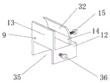
FIG. 5 is a perspective view of a positioning mechanism for the dropper;
FIG. 6 is a state diagram of the positioning of the dropper strip by the dropper positioning mechanism;
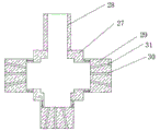
FIG. 7 is a schematic view of the structure of the head;
FIG. 8 is a schematic view of the structure of the connector;
fig. 9 is an installation view of the dropper.
1-a greenhouse main body; 2-a lifting frame; 3-lifting the vertical frame; 4-screw rod; 5-a slide block; 6-a servo motor; 7-a transverse frame; 8-a connector; 9-burette positioning mechanism; 10-a dropper; 11-a water dropper; 12-a bottom block; 13-fixing the plate; 14-a clamping plate; 15-adjusting the bolt; 16-a second water inlet pipe; 17-branch pipe; 18-a spray head; 19-a receiving groove; 20-a first water inlet pipe; 21-connecting blocks; 22-a groove; 23-a connecting rod; 24-a telescopic cavity; 25-a first positioning bolt; 26-a second positioning bolt; 27-a central block; 28-connecting pipe; 29-a spray head; 30-horizontal jet holes; 31-oblique injection hole; 32-a retaining part; 33-a switching valve; 34-a base; 35-a chute; 36-third positioning bolt.
Detailed Description
The following description is made with reference to the accompanying drawings and examples, but not to be construed as limiting the invention.
Example (b): a stereoscopic uniform irrigation greenhouse drip irrigation system is shown in figures 1-9 and comprises a greenhouse main body 1, wherein a square lifting frame 2 is arranged in the greenhouse main body 1, a plurality of lifting vertical frames 3 are arranged at the bottom of the lifting frame 2, and a vertical upward screw rod 4 is arranged in each lifting vertical frame 3 as shown in figure 2; a sliding block 5 in threaded fit with the screw 4 is arranged in the lifting vertical frame 3, and the sliding block 5 is connected with the lifting frame 2; a servo motor 6 is arranged at the bottom of the lifting vertical frame 3, and an output shaft of the servo motor 6 is connected with the screw rod 4; a plurality of cross frames 7 are arranged in the lifting frame 2, and two ends of each cross frame 7 are connected with the lifting frame 2 through connecting pieces 8; as shown in fig. 3, 4 and 8, the connecting member 8 includes a connecting block 21, a groove 22 for engaging with the frame of the lifting frame 2 is formed on the outer end of the connecting block 21, and a connecting rod 23 is arranged on the inner end of the connecting block 21; the end part of the transverse frame 7 is provided with a telescopic cavity 24 matched with the connecting rod 23; the transverse frame 7 is provided with a first positioning bolt 25 for fixing the connecting rod 23; the connecting block 21 is provided with a second positioning bolt 26, and the connecting block 21 is fixed with the frame of the lifting frame 2 through the second positioning bolt 26; the connecting piece 8 with the structure is convenient for dismounting the transverse frames 7, and can realize the position change of the transverse frames 7 to adjust the installation distance between the transverse frames 7.
As shown in fig. 9, a plurality of dropper positioning mechanisms 9 are arranged on the transverse frame 7 in parallel, a plurality of droppers 10 distributed longitudinally are fixed on the transverse frame 7 through the dropper positioning mechanisms 9, and a plurality of droppers 11 are arranged on the droppers 10; as shown in fig. 5 and 6, the burette positioning mechanism 9 includes a bottom block 12 disposed on the top of the cross frame 7, a fixing plate 13 is disposed on one side of the bottom block 12, a base 34 is further disposed on the bottom block 12, a threaded hole is disposed on the base 34, an adjusting bolt 15 is connected to the threaded hole of the base 34 via an internal thread, a clamping plate 14 disposed opposite to the fixing plate 13 is connected to the inner end of the adjusting bolt 15, and a retaining portion 32 bent to incline inward is disposed on the top of the clamping plate 14; the dropper has the advantages that the dropper belt is prevented from falling off from the dropper positioning mechanism, the buffer layers are arranged on the inner side wall of the clamping plate 14 and the inner side wall of the fixing plate 13, and are rubber layers or foam layers, so that the buffer and abrasion-proof effects are achieved. In practical application, the side walls of the holding plate 14 and the fixing plate 13 may be formed with arc-shaped grooves matching the outer contour of the dropper 10. The bottom of the bottom block 12 is provided with a sliding groove 35, the side wall of the bottom block 12 is provided with a third positioning bolt 36, and the bottom block 12 is fixed with the cross frame 7 through the third positioning bolt 36; the bottom block 12 can be moved along the cross frame 7, the mounting position of the dropper positioning mechanism 9 can be changed and adjusted, the bottom block 12 can be positioned through the third positioning bolt 36, and the mounting distance of the droppers 10 can be adjusted and changed to meet the requirements of plants with different planting distances in the greenhouse; the clamping plate 14 and the fixing plate 13 are matched to form a clamping opening, the dropper 10 is clamped and fixed through the clamping opening, the adjusting bolt 15 is rotated when the dropper 10 is clamped and fixed, the dropper 10 is clamped and fixed through the clamping plate 14, the dropper 10 with different thicknesses can be clamped and fixed, and the universality is high.
A transverse second water inlet pipe 16 is arranged at the bottom of the transverse frame 7, a plurality of vertically downward branch pipes 17 are connected to the second water inlet pipe 16, and switch valves 33 are arranged on the branch pipes 17; the spray head can be controlled to spray, and the bottom of the branch pipe 17 is provided with the spray head 18; as shown in fig. 7, the nozzle 18 includes a center block 27 having a hollow inside, and a connection pipe 28 connected to the branch pipe 17 is provided on the top of the center block 27; the side wall and the bottom of the central block are respectively provided with an injection head 29, the center of the injection head 29 is provided with a horizontal injection hole 30 communicated with the cavity, the periphery of the horizontal injection hole 30 is provided with a plurality of inclined injection holes 31 distributed annularly, the injection head 18 adopting the structure can realize large-range large-angle spraying, and the sprayed water mist is uniform. The horizontal frame of the lifting frame 2 is provided with a containing groove 19, a first water inlet pipe 20 is arranged in the containing groove 19, and the dropper 10 is connected with the first water inlet pipe 20.
The working principle is as follows: the screw rod 4 is driven to rotate by the servo motor 6, the rotating screw rod 4 drives the sliding block 5 to move up and down, and further drives the lifting frame 2 to lift, so that the heights of the dropper 10 and the sprayer 11 arranged on the lifting frame 2 are adjusted in a lifting mode, the dropper 10 does not need to be wound when the land is ploughed, and a large amount of manpower and material resources are saved; furthermore, the spray head 18 provided on the branch pipe 17 and the drip head provided on the drip pipe 10 can effectively perform three-dimensional uniform spraying. The utility model provides a burette 10 is located on crossbearer 7 through burette positioning mechanism 9, and wherein burette positioning mechanism 9 is including setting up bottom block 12 at crossbearer 7 top, and one side of bottom block 12 is equipped with fixed plate 13, still be equipped with base 34 on the bottom block 12, set up threaded hole on the base 34, and threaded hole female connection of base 34 has adjusting bolt 15, and adjusting bolt 15's interior end connection has the grip block 14 that sets up with fixed plate 13 is relative, and wherein grip block 14 forms the centre gripping mouth with the cooperation of fixed plate 13, and it is fixed to utilize the centre gripping mouth to carry out the centre gripping to burette 10, when carrying out the centre gripping to burette 10 fixedly, rotates adjusting bolt 15, and it is fixed to realize that grip block 14 carries out the centre gripping to burette 10, can carry out the centre gripping to the bure.
A transverse second water inlet pipe 16 is arranged at the bottom of the transverse frame 7, a plurality of vertically downward branch pipes 17 are connected to the second water inlet pipe 16, spray heads 18 are arranged at the bottoms of the branch pipes 17, each spray head 18 comprises a central block 27 with a cavity arranged inside, and a connecting pipe 28 connected with the branch pipes 17 is arranged at the top of the central block 27; the side wall and the bottom of the central block are respectively provided with an injection head 29, the center of the injection head 29 is provided with a horizontal injection hole 30 communicated with the cavity, the periphery of the horizontal injection hole 30 is provided with a plurality of inclined injection holes 31 distributed annularly, the injection head 18 adopting the structure can realize large-range large-angle spraying, and the sprayed water mist is uniform.
Claims (7)
1. A stereoscopic uniform irrigation greenhouse drip irrigation system comprises a greenhouse main body (1), wherein a square lifting frame (2) is arranged at the upper part of the greenhouse main body (1), a plurality of lifting vertical frames (3) are arranged at the bottom of the lifting frame (2), and vertically upward screw rods (4) are arranged in the lifting vertical frames (3); a sliding block (5) in threaded fit with the screw rod (4) is arranged in the lifting vertical frame (3), and the sliding block (5) is connected with the lifting frame (2); a servo motor (6) is arranged at the bottom of the lifting vertical frame (3), an output shaft of the servo motor (6) is connected with the screw (4), a containing groove (19) is arranged on a transverse frame of the lifting frame (2), and a first water inlet pipe (20) is arranged in the containing groove (19); the method is characterized in that: a plurality of cross frames (7) are arranged in the lifting frame (2), and two ends of each cross frame (7) are respectively connected with the lifting frame (2) through connecting pieces (8); a plurality of dropper positioning mechanisms (9) are arranged on the transverse frame (7), a plurality of droppers (10) which are longitudinally distributed are fixed on the transverse frame (7) through the dropper positioning mechanisms (9), and a plurality of drippers (11) are arranged on the droppers (10); the burette positioning mechanism (9) comprises a bottom block (12) arranged at the top of the transverse frame (7), a fixing plate (13) is arranged on one side of the bottom block (12), a base (34) is further arranged on the bottom block (12), a threaded hole is formed in the base (34), an adjusting bolt (15) is connected to the threaded hole of the base (34) in an internal thread manner, and a clamping plate (14) which is arranged opposite to the fixing plate (13) is connected to the inner end portion of the adjusting bolt (15); the dropper (10) is connected with the first water inlet pipe (20).
2. The stereoscopic uniform irrigation greenhouse drip irrigation system according to claim 1, wherein: the connecting piece (8) comprises a connecting block (21), a groove (22) used for clamping the frame of the lifting frame (2) is formed in the outer end part of the connecting block (21), and a connecting rod (23) is arranged in the inner end part of the connecting block (21); the end part of the transverse frame (7) is provided with a telescopic cavity (24) matched with the connecting rod (23); the transverse frame (7) is provided with a first positioning bolt (25) for fixing the connecting rod (23); and a second positioning bolt (26) is arranged on the connecting block (21), and the connecting block (21) is fixed with the frame of the lifting frame (2) through the second positioning bolt (26).
3. The stereoscopic uniform irrigation greenhouse drip irrigation system according to claim 1, wherein: a transverse second water inlet pipe (16) is arranged at the bottom of the transverse frame (7), a plurality of vertically downward branch pipes (17) are connected to the second water inlet pipe (16), spray heads (18) are arranged at the bottoms of the branch pipes (17), each spray head (18) comprises a central block (27) with a cavity inside, and a connecting pipe (28) connected with the branch pipes (17) is arranged at the top of each central block (27); the side wall and the bottom of the central block are respectively provided with an injection head (29), the center of the injection head (29) is provided with a horizontal injection hole (30), and the periphery of the horizontal injection hole (30) is provided with a plurality of inclined injection holes (31) distributed annularly.
4. The stereoscopic uniform irrigation greenhouse drip irrigation system according to claim 1, wherein: the top of the clamping plate (14) is provided with an anti-falling part (32) which is bent inwards in an inclined way.
5. The stereoscopic uniform irrigation greenhouse drip irrigation system according to claim 1, wherein: buffer layers are arranged on the inner side wall of the clamping plate (14) and the inner side wall of the fixing plate (13), and the buffer layers are rubber layers or foam layers.
6. The stereoscopic uniform irrigation greenhouse drip irrigation system according to claim 3, wherein: the branch pipe (17) is provided with a switch valve (33).
7. The stereoscopic uniform irrigation greenhouse drip irrigation system according to claim 1, wherein: the bottom of bottom block (12) is equipped with spout (35), be equipped with third positioning bolt (36) on bottom block (12) lateral wall, bottom block (12) are fixed with crossbearer (7) through third positioning bolt (36).
Priority Applications (1)
| Application Number | Priority Date | Filing Date | Title |
|---|---|---|---|
| CN201920590699.XU CN210076191U (en) | 2019-04-28 | 2019-04-28 | Stereoscopic greenhouse drip irrigation system capable of achieving uniform irrigation |
Applications Claiming Priority (1)
| Application Number | Priority Date | Filing Date | Title |
|---|---|---|---|
| CN201920590699.XU CN210076191U (en) | 2019-04-28 | 2019-04-28 | Stereoscopic greenhouse drip irrigation system capable of achieving uniform irrigation |
Publications (1)
| Publication Number | Publication Date |
|---|---|
| CN210076191U true CN210076191U (en) | 2020-02-18 |
Family
ID=69476169
Family Applications (1)
| Application Number | Title | Priority Date | Filing Date |
|---|---|---|---|
| CN201920590699.XU Expired - Fee Related CN210076191U (en) | 2019-04-28 | 2019-04-28 | Stereoscopic greenhouse drip irrigation system capable of achieving uniform irrigation |
Country Status (1)
| Country | Link |
|---|---|
| CN (1) | CN210076191U (en) |
Cited By (5)
| Publication number | Priority date | Publication date | Assignee | Title |
|---|---|---|---|---|
| CN111296033A (en) * | 2020-03-02 | 2020-06-19 | 广东省农业科学院蔬菜研究所 | Spraying system and vegetable planting method |
| CN112020975A (en) * | 2020-09-10 | 2020-12-04 | 和县德生农业发展有限公司 | Water and fertilizer integrated system based on Internet of things and implementation method thereof |
| CN112314291A (en) * | 2020-11-09 | 2021-02-05 | 中国水利水电科学研究院 | Rain shielding test system for drip irrigation and micro-spray irrigation of crops |
| CN112470662A (en) * | 2020-11-30 | 2021-03-12 | 张翠 | A quantitative drip irrigation equipment that is used for mango seedling water manure integration of growing seedlings |
| CN116058262A (en) * | 2022-11-23 | 2023-05-05 | 山东农业大学 | Agricultural planting watering device |
-
2019
- 2019-04-28 CN CN201920590699.XU patent/CN210076191U/en not_active Expired - Fee Related
Cited By (5)
| Publication number | Priority date | Publication date | Assignee | Title |
|---|---|---|---|---|
| CN111296033A (en) * | 2020-03-02 | 2020-06-19 | 广东省农业科学院蔬菜研究所 | Spraying system and vegetable planting method |
| CN112020975A (en) * | 2020-09-10 | 2020-12-04 | 和县德生农业发展有限公司 | Water and fertilizer integrated system based on Internet of things and implementation method thereof |
| CN112314291A (en) * | 2020-11-09 | 2021-02-05 | 中国水利水电科学研究院 | Rain shielding test system for drip irrigation and micro-spray irrigation of crops |
| CN112470662A (en) * | 2020-11-30 | 2021-03-12 | 张翠 | A quantitative drip irrigation equipment that is used for mango seedling water manure integration of growing seedlings |
| CN116058262A (en) * | 2022-11-23 | 2023-05-05 | 山东农业大学 | Agricultural planting watering device |
Similar Documents
| Publication | Publication Date | Title |
|---|---|---|
| CN210076191U (en) | Stereoscopic greenhouse drip irrigation system capable of achieving uniform irrigation | |
| CN113455353A (en) | Agricultural planting removes spray irrigation equipment | |
| CN113767838A (en) | Irrigation equipment is planted to crops | |
| CN210042872U (en) | Movable sprinkling irrigation device | |
| CN212786843U (en) | Height-adjustable formula irrigation equipment for warmhouse booth | |
| CN110959509B (en) | Wall green plant movable irrigation device and method | |
| CN111406549A (en) | Multi-functional flower nursery planting machine of rail mounted | |
| CN217284355U (en) | Farmland irrigation device | |
| CN207692814U (en) | A kind of pesticide automatic sprinkler system for greenhouse | |
| CN207767342U (en) | A kind of wine-growing pesticide spraying device | |
| CN207269462U (en) | A kind of wine-growing greenhouse | |
| CN215735769U (en) | Multifunctional grape planting fertilizing equipment with adjustable fertilizing interval | |
| CN211322383U (en) | Self-propelled seedling growing sprinkler | |
| CN209359231U (en) | A kind of high moisturizing dendrobium candidum planting greenhouse | |
| CN221843590U (en) | Pesticide spraying vehicle with adjustable pesticide spraying distance | |
| CN206042998U (en) | A kind of reciprocal sprinkler of electric-controlled type | |
| CN219762322U (en) | Pest control device for vegetable planting | |
| CN215648513U (en) | Lifting support is planted to grape | |
| CN219396024U (en) | Pesticide sprinkler for corn and soybean banded composite planting | |
| CN217742879U (en) | Grape seedling stage sprayer | |
| CN218353218U (en) | Grape is planted and is used water jet equipment | |
| CN218499664U (en) | A bed of growing seedlings for chinese-medicinal material is planted | |
| CN218526995U (en) | Water conservation is grown seedlings and is sprayed irrigation equipment | |
| CN214282384U (en) | Farming is with high farming frame of stability | |
| CN219939204U (en) | Drip irrigation device for tea planting |
Legal Events
| Date | Code | Title | Description |
|---|---|---|---|
| GR01 | Patent grant | ||
| GR01 | Patent grant | ||
| CF01 | Termination of patent right due to non-payment of annual fee | ||
| CF01 | Termination of patent right due to non-payment of annual fee |
Granted publication date: 20200218 Termination date: 20210428 |