CN210075851U - Multilayer circuit board with dustproof function - Google Patents
Multilayer circuit board with dustproof function Download PDFInfo
- Publication number
- CN210075851U CN210075851U CN201920690244.5U CN201920690244U CN210075851U CN 210075851 U CN210075851 U CN 210075851U CN 201920690244 U CN201920690244 U CN 201920690244U CN 210075851 U CN210075851 U CN 210075851U
- Authority
- CN
- China
- Prior art keywords
- groove
- circuit board
- movable
- support
- multilayer circuit
- Prior art date
- Legal status (The legal status is an assumption and is not a legal conclusion. Google has not performed a legal analysis and makes no representation as to the accuracy of the status listed.)
- Active
Links
Images


Abstract
The utility model discloses a can have multilayer circuit board of dustproof function, including support and activity groove, the inside of support has been seted up and has been put the thing groove, and put the upper and lower both ends in thing groove and all be provided with and accept the board, the inside of accepting the board simultaneously passes through spliced pole and connecting hole and fixed plate interconnect, the inside of fixed plate is provided with the clamp plate, and the outer end of clamp plate is fixed with the support column, the outer end of support column is through flexible groove and supporting spring and support sleeve interconnect simultaneously, the activity groove is seted up respectively and is put both ends about the thing groove, and the inside in activity groove all is provided with the movable frame, the inside of movable frame is provided with the fan, and the outer end of movable frame all is through control groove and control column interconnect, the lower extreme of simultaneous control post all is connected with the motor, both ends all are. This can have dustproof function's multilayer circuit board, the installation of device and circuit board of not only being convenient for can increase the dustproof and radiating effect of circuit board simultaneously.
Description
Technical Field
The utility model relates to a circuit board technical field specifically is a multilayer circuit board that can have dustproof function.
Background
The circuit board mainly comprises a bonding pad, a through hole, a mounting hole, a lead, a component, a connector, a filler, an electrical boundary and the like, so that the circuit is miniaturized and visualized, and plays an important role in batch production of fixed circuits and optimization of electrical appliance layout.
However, most of the existing multilayer circuit boards have dust accumulation in the use process due to the self structure, so that the heat dissipation performance of the circuit boards is reduced, and the working efficiency of the circuit boards is reduced. Aiming at the problems, the novel design is carried out on the basis of the original multilayer circuit board.
SUMMERY OF THE UTILITY MODEL
Technical problem to be solved
The utility model provides a not enough to prior art, the utility model provides a can have dustproof function's multilayer circuit board has solved present most of multilayer circuit boards and has piled up because self structure leads to the dust in the use, makes circuit board heat dispersion descend to the work efficiency's of circuit board problem has been reduced.
(II) technical scheme
In order to achieve the above object, the utility model provides a following technical scheme: a multi-layer circuit board with a dustproof function comprises a bracket and a movable groove, wherein a storage groove is arranged in the bracket, bearing plates are arranged at the upper end and the lower end of the storage groove, meanwhile, the interior of the bearing plate is connected with the fixed plate through the connecting column and the connecting hole, the interior of the fixed plate is provided with a pressing plate, the outer end of the pressing plate is fixed with a supporting column, meanwhile, the outer ends of the supporting columns are connected with the supporting sleeves through the telescopic grooves and the supporting springs, the movable grooves are respectively arranged at the left end and the right end of the object placing groove, and the movable frames are arranged inside the movable grooves, the fans are arranged inside the movable frames, the outer ends of the movable frames are connected with the control columns through the control grooves, meanwhile, the lower ends of the control columns are connected with motors, the front end and the rear end of the movable frame are respectively fixed with a sliding block, and the movable frame is connected with the sliding grooves through the sliding blocks, and the sliding grooves are respectively arranged at the front end and the rear end of the movable groove.
Preferably, the bearing plate and the bracket are of a welded integrated structure, and four bearing plates are symmetrically distributed on the vertical axis of the bracket.
Preferably, the outer surface of the connecting column and the inner surface of the connecting hole are both in thread structures and are in threaded connection.
Preferably, the width of the fixing plate is smaller than that of the storage groove, and the longitudinal section of the fixing plate is of a concave structure.
Preferably, the support column forms a telescopic mechanism with the support sleeve through the telescopic groove and the support spring, and the initial length of the support spring is equal to the depth of the telescopic groove.
Preferably, the movable frame forms a sliding mechanism with the movable groove through the sliding block and the sliding groove, and the two movable frames are symmetrically distributed about a vertical axis of the support.
Preferably, the outer surface of the control column and the inner surface of the control groove are both in a thread structure, and the control column is rotatably connected with the bracket.
(III) advantageous effects
The utility model provides a can have dustproof function's multilayer circuit board. The method has the following beneficial effects:
(1) this can have the multilayer circuit board of dustproof function, the setting of accepting the board has strengthened the steadiness of being connected of fixed plate and support, has improved the stationary force of device to the circuit board, the structure convenient to use person of spliced pole and connecting hole is dismantled and is installed the fixed plate, the availability factor of improving device, the size convenient to use person of fixed plate packs up the fixed plate to putting the thing groove, the structure of fixed plate is convenient for fix and draw in the front and back both ends of circuit board simultaneously.
(2) This can have the multilayer circuit board of dustproof function, the support column is convenient for carry out the pressfitting to the circuit board of different thickness with the structure that supports the cover, improves the suitability of device, and the structure of movable frame and activity groove is convenient for change the wind direction of fan, improves the dustproof effect of device, is convenient for dispel the heat to the circuit board of putting in the thing groove simultaneously, and the structure of control column and control groove has improved the steadiness that the two is connected, is convenient for adjust the position of movable frame simultaneously.
Drawings
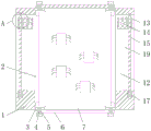
FIG. 1 is a schematic front view of the present invention;
FIG. 2 is a schematic side view of the present invention;
FIG. 3 is an enlarged schematic view of the structure at A of FIG. 1 according to the present invention;
fig. 4 is an enlarged schematic structural diagram of the point B in fig. 2 according to the present invention.
In the figure: 1. a support; 2. a storage groove; 3. a bearing plate; 4. connecting columns; 5. connecting holes; 6. a fixing plate; 7. pressing a plate; 8. a support pillar; 9. a telescopic groove; 10. a support spring; 11. a support sleeve; 12. a movable groove; 13. a movable frame; 14. a fan; 15. a control column; 16. a control slot; 17. a motor; 18. a slider; 19. a chute.
Detailed Description
The technical solutions in the embodiments of the present invention will be described clearly and completely with reference to the accompanying drawings in the embodiments of the present invention, and it is obvious that the described embodiments are only some embodiments of the present invention, not all embodiments. Based on the embodiments in the present invention, all other embodiments obtained by a person skilled in the art without creative work belong to the protection scope of the present invention.
As shown in fig. 1-4, the utility model provides a technical solution: a multi-layer circuit board with a dustproof function comprises a support 1, a storage groove 2, a bearing plate 3, a connecting column 4, a connecting hole 5, a fixed plate 6, a pressing plate 7, a supporting column 8, a telescopic groove 9, a supporting spring 10, a supporting sleeve 11, a movable groove 12, a movable frame 13, a fan 14, a control column 15, a control groove 16, a motor 17, a sliding block 18 and a sliding groove 19, wherein the storage groove 2 is formed in the support 1, the bearing plates 3 are arranged at the upper end and the lower end of the storage groove 2, the inner part of the bearing plate 3 is connected with the fixed plate 6 through the connecting column 4 and the connecting hole 5, the pressing plate 7 is arranged in the fixed plate 6, the supporting column 8 is fixed at the outer end of the pressing plate 7, the outer end of the supporting column 8 is connected with the supporting sleeve 11 through the telescopic groove 9 and the supporting spring 10, the movable grooves 12 are respectively formed at the left end and the right end of, a fan 14 is arranged inside the movable frame 13, the outer end of the movable frame 13 is connected with a control column 15 through a control groove 16, the lower end of the control column 15 is connected with a motor 17, sliding blocks 18 are fixed at the front end and the rear end of the movable frame 13, the movable frame 13 is connected with a sliding groove 19 through the sliding blocks 18, and the sliding grooves 19 are respectively arranged at the front end and the rear end of the movable groove 12;
the bearing plates 3 and the bracket 1 are of a welding integrated structure, four bearing plates 3 are symmetrically distributed on a vertical axis of the bracket 1, the arrangement of the bearing plates 3 strengthens the connection stability of the fixing plate 6 and the bracket 1, and improves the fixing force of the device on a circuit board;
the outer surface of the connecting column 4 and the inner surface of the connecting hole 5 are both in threaded structures and are in threaded connection, the structure of the connecting column 4 and the connecting hole 5 is convenient for a user to detach and mount the fixing plate 6, and the use efficiency of the device is improved;
the width of the fixed plate 6 is smaller than that of the object placing groove 2, the longitudinal section of the fixed plate 6 is of a concave structure, the size of the fixed plate 6 is convenient for a user to fold the fixed plate 6 into the object placing groove, and meanwhile, the structure of the fixed plate 6 is convenient for fixing and folding the front end and the rear end of the circuit board;
the supporting column 8 and the supporting sleeve 11 form a telescopic mechanism through the telescopic groove 9 and the supporting spring 10, the initial length of the supporting spring 10 is equal to the depth of the telescopic groove 9, and the structures of the supporting column 8 and the supporting sleeve 11 are convenient for pressing circuit boards with different thicknesses, so that the applicability of the device is improved;
the movable frame 13 and the movable groove 12 form a sliding mechanism through the sliding block 18 and the sliding groove 19, two movable frames 13 are symmetrically distributed about a vertical axis of the bracket 1, and the structures of the movable frames 13 and the movable groove 12 are convenient for changing the wind direction of the fan 14, improving the dustproof effect of the device and simultaneously facilitating the heat dissipation of the circuit board in the object holding groove 2;
the surface of control post 15 and the internal surface of control groove 16 all are thread structure, and control post 15 rotates with support 1 to be connected, and control post 15 has improved the steadiness that the two are connected with the structure of control groove 16, is convenient for adjust the position of adjustable frame 13 simultaneously.
When the device is used, according to the figures 1 and 3, firstly, the circuit board is placed in the middle of the pressing plate 7, the pressing plate 7 drives the supporting column 8 to move towards the inside of the telescopic groove 9, meanwhile, the supporting spring 10 is in a compressed state, and the force which is applied to the supporting column 8 and the pressing plate 7 towards the circuit board is given, so that the pressure between the pressing plate 7 and the circuit board is increased, and the friction force between the pressing plate 7 and the circuit board is increased, then, a user only needs to grasp the fixing plate 6, place one end of the circuit board towards the inside of the storage groove 2, enable the lower end of the fixing plate 6 to be in mutual contact with the upper surface of the bearing plate 3, enable the connecting column 4 to penetrate through the connecting hole 5 towards the inside of the bearing plate 3, and connect the fixing plate 6 and the bearing plate 3;
according to fig. 2 and 4, when a user needs to dissipate heat and prevent dust for a circuit board, the user only needs to turn on the motor 17 clockwise when the circuit board works, where the motor 17 is a servo motor, and at this time, the motor 17 drives the control column 15 to rotate clockwise, so that the control column 15 drives the movable frame 13 to move downward through the threaded connection with the control slot 16, meanwhile, the sliding blocks 18 and the sliding grooves 19 at the front end and the rear end of the movable frame 13 can increase the stability of the movable frame 13 during sliding, when the movable frame 13 moves to the lower end of the control post 15, the motor 17 is started to rotate anticlockwise to drive the movable frame 13 to move towards the upper end of the control post 15, so that the position of the fan 14 is changed continuously, the dust removal and heat dissipation effects of the device are improved, and the use process of the multilayer circuit board with the dustproof function is realized, and those not described in detail in this specification are well within the skill of those in the art.
To sum up, the multi-layer circuit board with the dustproof function has the advantages that the arrangement of the bearing plate 3 strengthens the connection stability of the fixed plate 6 and the bracket 1, the fixing force of the device on the circuit board is improved, the structure of the connecting column 4 and the connecting hole 5 is convenient for a user to disassemble and install the fixed plate 6, the use efficiency of the device is improved, the size of the fixed plate 6 is convenient for the user to pack the fixed plate 6 into the storage groove 2, meanwhile, the structure of the fixed plate 6 is convenient for fixing and folding the front end and the rear end of the circuit board, the structure of the supporting column 8 and the supporting sleeve 11 is convenient for pressing the circuit boards with different thicknesses, the applicability of the device is improved, the structures of the movable frame 13 and the movable groove 12 are convenient for changing the wind direction of the fan 14, the dustproof effect of the device is improved, meanwhile, the heat dissipation of the circuit board in the storage groove 2 is convenient, and the connection stability, while facilitating adjustment of the position of the movable frame 13.
It is noted that, herein, relational terms such as first and second, and the like may be used solely to distinguish one entity or action from another entity or action without necessarily requiring or implying any actual such relationship or order between such entities or actions. Also, the terms "comprises," "comprising," or any other variation thereof, are intended to cover a non-exclusive inclusion, such that a process, method, article, or apparatus that comprises a list of elements does not include only those elements but may include other elements not expressly listed or inherent to such process, method, article, or apparatus. Without further limitation, an element defined by the phrase "comprising an … …" does not exclude the presence of other identical elements in a process, method, article, or apparatus that comprises the element.
Although embodiments of the present invention have been shown and described, it will be appreciated by those skilled in the art that changes, modifications, substitutions and alterations can be made in these embodiments without departing from the principles and spirit of the invention, the scope of which is defined in the appended claims and their equivalents.
Claims (7)
1. A multilayer circuit board that can have dustproof function, includes support (1) and activity groove (12), its characterized in that: the rack is characterized in that a storage groove (2) is formed in the rack (1), the upper end and the lower end of the storage groove (2) are provided with bearing plates (3), the inner part of the bearing plates (3) is connected with a fixed plate (6) through connecting columns (4) and connecting holes (5), pressing plates (7) are arranged in the fixed plate (6), supporting columns (8) are fixed at the outer ends of the pressing plates (7), the outer ends of the supporting columns (8) are connected with a supporting sleeve (11) through telescopic grooves (9) and supporting springs (10), movable grooves (12) are formed in the left end and the right end of the storage groove (2), movable frames (13) are arranged in the movable grooves (12), fans (14) are arranged in the movable frames (13), the outer ends of the movable frames (13) are connected with control columns (15) through control grooves (16), and motors (17) are connected with the lower ends of the control columns (15), the front end and the rear end of the movable frame (13) are both fixed with sliding blocks (18), the movable frame (13) is connected with sliding grooves (19) through the sliding blocks (18), and the sliding grooves (19) are respectively arranged at the front end and the rear end of the movable groove (12).
2. The multilayer circuit board with a dustproof function according to claim 1, wherein: the bearing plate (3) and the support (1) are of a welding integrated structure, and four bearing plates (3) are symmetrically distributed on the vertical axis of the support (1).
3. The multilayer circuit board with a dustproof function according to claim 1, wherein: the outer surface of the connecting column (4) and the inner surface of the connecting hole (5) are both in thread structures and are in threaded connection.
4. The multilayer circuit board with a dustproof function according to claim 1, wherein: the width of the fixed plate (6) is less than that of the object placing groove (2), and the longitudinal section of the fixed plate (6) is of a concave structure.
5. The multilayer circuit board with a dustproof function according to claim 1, wherein: the support column (8) and the support sleeve (11) form a telescopic mechanism through a telescopic groove (9) and a support spring (10), and the initial length of the support spring (10) is equal to the depth of the telescopic groove (9).
6. The multilayer circuit board with a dustproof function according to claim 1, wherein: the movable frame (13) and the movable groove (12) form a sliding mechanism through a sliding block (18) and a sliding groove (19), and two movable frames (13) are symmetrically distributed around the vertical axis of the support (1).
7. The multilayer circuit board with a dustproof function according to claim 1, wherein: the outer surface of the control column (15) and the inner surface of the control groove (16) are both in thread structures, and the control column (15) is rotatably connected with the bracket (1).
Priority Applications (1)
| Application Number | Priority Date | Filing Date | Title |
|---|---|---|---|
| CN201920690244.5U CN210075851U (en) | 2019-05-14 | 2019-05-14 | Multilayer circuit board with dustproof function |
Applications Claiming Priority (1)
| Application Number | Priority Date | Filing Date | Title |
|---|---|---|---|
| CN201920690244.5U CN210075851U (en) | 2019-05-14 | 2019-05-14 | Multilayer circuit board with dustproof function |
Publications (1)
| Publication Number | Publication Date |
|---|---|
| CN210075851U true CN210075851U (en) | 2020-02-14 |
Family
ID=69451996
Family Applications (1)
| Application Number | Title | Priority Date | Filing Date |
|---|---|---|---|
| CN201920690244.5U Active CN210075851U (en) | 2019-05-14 | 2019-05-14 | Multilayer circuit board with dustproof function |
Country Status (1)
| Country | Link |
|---|---|
| CN (1) | CN210075851U (en) |
-
2019
- 2019-05-14 CN CN201920690244.5U patent/CN210075851U/en active Active
Similar Documents
| Publication | Publication Date | Title |
|---|---|---|
| CN205184127U (en) | Circuit board soldering anchor clamps | |
| CN210075851U (en) | Multilayer circuit board with dustproof function | |
| CN215745670U (en) | Plate bending device | |
| US20200359784A1 (en) | Electric table stand for simple assembly and adjustment | |
| CN211240365U (en) | Positioning device for welding integrated circuit board | |
| CN217467647U (en) | Program burning device for PCBA | |
| CN217278796U (en) | Power-on detection device for integrated circuit board | |
| CN212683067U (en) | Special-shaped elastic part mounting mechanism for PCB | |
| CN112996268B (en) | Fixed clamping platform for maintaining and processing flexible circuit board | |
| CN108788371B (en) | Anti-drop's electronic components welding uses support frame | |
| CN103124303B (en) | Multifunctional cellphone radiating support | |
| CN114269078A (en) | A pressfitting machine for printed circuit board production | |
| CN220857453U (en) | ZT cabinet line wiring tool with wire arranging device | |
| CN112845943A (en) | A rectangular iron plate rounding equipment for hardware processing | |
| CN211529793U (en) | Integral type pipe electric capacity foot rest | |
| CN216491274U (en) | Low-impedance multilayer circuit board | |
| CN220019801U (en) | PCB board test fixture | |
| CN213341329U (en) | Electrical equipment fixing device | |
| CN211952074U (en) | Lifting interactive projection device | |
| CN214505913U (en) | Conveniently-connected carriage grade plate card connector | |
| CN219436632U (en) | Adjustable distribution frame | |
| CN212045074U (en) | Formula of making an uproar PCB drilling equipment is used in panel processing of falling | |
| CN213662070U (en) | Clamping device is used in circuit board processing | |
| CN213718320U (en) | Flexible circuit board jig | |
| CN212191670U (en) | Heat-dissipation energy-saving electric welding machine |
Legal Events
| Date | Code | Title | Description |
|---|---|---|---|
| GR01 | Patent grant | ||
| GR01 | Patent grant |