CN210061131U - Intelligent detection balance crane mechanical arm device - Google Patents
Intelligent detection balance crane mechanical arm device Download PDFInfo
- Publication number
- CN210061131U CN210061131U CN201920967013.4U CN201920967013U CN210061131U CN 210061131 U CN210061131 U CN 210061131U CN 201920967013 U CN201920967013 U CN 201920967013U CN 210061131 U CN210061131 U CN 210061131U
- Authority
- CN
- China
- Prior art keywords
- supporting plate
- support plate
- screw rod
- mechanical arm
- motor
- Prior art date
- Legal status (The legal status is an assumption and is not a legal conclusion. Google has not performed a legal analysis and makes no representation as to the accuracy of the status listed.)
- Expired - Fee Related
Links
Images


Abstract
The utility model discloses an intelligent detection balance crane mechanical arm device, which comprises a base, a motion frame, a first supporting plate, a second supporting plate and a third supporting plate; a first servo motor is fixedly arranged above the center of the first supporting plate, and an output shaft of the first servo motor penetrates through the second supporting plate and is fixedly connected with the third supporting plate through a coupler; an upright post is fixedly arranged on the third support plate, the top of the upright post is fixedly connected with a fifth support plate, and a fourth support plate is arranged between the fifth support plate and the third support plate; a direct current motor is fixedly arranged on the fifth supporting plate, an output shaft of the direct current motor is vertically and downwards connected with a first screw rod through a coupler, and the first screw rod penetrates through the fourth supporting plate; a mechanical arm is fixedly arranged on the fourth supporting plate and comprises a horizontally placed cross beam, a grabbing device arranged at one end of the cross beam and a counterweight device arranged at the other end of the cross beam; the first screw rod penetrates through the cross beam, and a pressure sensor is arranged on the grabbing device.
Description
Technical Field
The utility model belongs to the technical field of industrial automation, concretely relates to balanced jack-up mechanical arm device is examined to intelligence.
Background
In an industrial production line, products of different specifications and sizes are often packed or stacked in high quality on the production line, and the mechanical arm is uneven in stress caused by different weights for grabbing the products in different working environments, so that the mechanical arm device is seriously abraded, and the mechanical arm is easy to deform under the long-term working state of uneven stress. In another multilayer superposed assembly line in industrial production, the motion control of a common six-degree-of-freedom manipulator in the working environment is complicated, and the working efficiency is not high.
Disclosure of Invention
Not enough to prior art, the utility model provides a balanced jack-up mechanical arm device is examined to intelligence.
The technical scheme of the utility model as follows: an intelligent detection balance crane mechanical arm device comprises a base, wherein a moving frame capable of moving along the X direction is arranged on the base, and a first supporting plate capable of moving along the Y direction is further arranged on the moving frame; a second support plate is arranged in parallel right above the first support plate, the first support plate and the second support plate are fixedly connected through a screw rod, and a third support plate is arranged in parallel right above the second support plate; a first servo motor is fixedly arranged above the center of the first supporting plate, and an output shaft of the first servo motor penetrates through the second supporting plate and is fixedly connected with the third supporting plate through a coupler; an upright post is fixedly arranged on the third support plate, the top of the upright post is fixedly connected with a fifth support plate, and a fourth support plate is arranged between the fifth support plate and the third support plate; a direct current motor is fixedly arranged on the fifth supporting plate, an output shaft of the direct current motor is vertically and downwards connected with a first screw rod through a coupler, and the lower end of the first screw rod is connected with the third supporting plate through a bearing seat; the center of the lower surface of the fourth supporting plate is fixedly connected with a screw nut, and the first screw rod penetrates through the fourth supporting plate and the screw nut; a mechanical arm is fixedly arranged on the fourth supporting plate and comprises a horizontally placed cross beam, a grabbing device arranged at one end of the cross beam and a counterweight device arranged at the other end of the cross beam; the first screw rod penetrates through the cross beam, and a pressure sensor is arranged on the grabbing device.
Furthermore, a plurality of clamping wheels are fixedly arranged at the outer edge below the third supporting plate, each clamping wheel comprises a pair of upper wheels and lower wheels, and the upper wheels and the lower wheels clamp the upper surface and the lower surface of the second supporting plate; the third supporting plate drives the clamping wheel to rotate 360 degrees in a plane under the driving of the first servo motor.
Furthermore, the counterweight device comprises a third stepping motor, a second screw rod and a counterweight block, wherein an output shaft of the third stepping motor is connected with the second screw rod through a coupler, and the second screw rod penetrates through the counterweight block through a threaded hole formed in the counterweight block; the position of the balancing weight on the second screw rod is driven by a third stepping motor, so that the balance of the cross beam is kept;
further, grabbing device is including erecting the roof beam, erects the middle part and crossbeam fixed connection of roof beam, and the terminal fixed mounting who erects the roof beam has second servo motor, and second servo motor's output shaft is vertical downwards, through shaft coupling and the swivel mount fixed connection of its below, and the swivel mount is connected with four claw dishes of below, and the terminal shape of every claw of four claw dishes is U type groove, and every U type inslot articulates there is the finger, and the finger end is provided with the palm, is provided with in the face that the palm is relative pressure sensor.
Further, a worm speed-reducing self-locking motor is further arranged inside the rotating frame, and an output shaft of the worm speed-reducing self-locking motor is vertically downward and is connected with a third screw rod through a coupling; a cross is further arranged between the four-jaw disc and the rotating frame, a feed screw nut is fixedly connected below the center of the cross, and a third feed screw penetrates through the cross and the feed screw nut; each arm of the cross is hinged with a double-head U-shaped groove connecting piece, the other end of each double-head U-shaped groove connecting piece is hinged with the top end of each finger, and each double-head U-shaped groove connecting piece is positioned right above each claw of the four-claw disc.
The utility model discloses an actively beneficial effect:
(1) the motion in the XY plane of the mechanical arm device can be realized under the driving of the first stepping motor and the second stepping motor by arranging an optical axis in the direction of X, Y, a box-type sliding block and the like; the mechanical arm device can be lifted along the Z direction under the driving of the direct current motor through the optical axis in the Z direction, the first screw rod and the like;
(2) the second supporting plate is clamped by a plurality of clamping wheels, and the third supporting plate and the mechanical arm above the third supporting plate can do 360-degree rotary motion in a plane under the driving of the first servo motor, and the motion is stable because of the clamping wheels;
(3) through the arrangement of the counterweight device, the counterweight device is matched with the pressure sensor, the distance of the counterweight block can be moved under the driving of the third step motor according to the weight difference of the clamped articles, so that the mechanical arm keeps intelligent detection balance constantly, and the abrasion of the mechanical arm is reduced;
(4) the second servo motor arranged on the grabbing device can realize 360-degree rotation of fingers and a palm in a plane; through the mutual cooperation of worm speed reduction self-locking motor, cross, two U groove connecting pieces, the fixed disk in four U type grooves in area, can realize tightening up and relaxing of finger and palm, can realize grabbing, promoting, rotatory, decline, loosening all functions such as to article, adaptable different operational environment promotes work efficiency greatly.
Drawings
Fig. 1 is the three-dimensional structure schematic diagram of the intelligent balance crane arm device of the utility model.
FIG. 2 is a partial structural view of the rotating part of the third support plate.
Fig. 3 is a schematic view of the counterweight device.
Fig. 4 is a schematic structural view of the grasping apparatus.
FIG. 5 is a schematic view of a four-jaw disc structure.
Reference numerals: the device comprises a base, 2 first stepping motors, 3 second stepping motors, 4X-direction optical axis supporting seats, 5 box-type sliders, 6 moving frames, 7 first servo motors, 8Y-direction optical axis supporting seats, 9 first supporting plates, 10 second supporting plates, 11 third supporting plates, 12 fourth supporting plates, 13 first screw rods, 14 fifth supporting plates, 15 direct current motors, 16 third stepping motors, 161 second screw rods, 17 balance weights, 18 second servo motors, 19 rotating frames, 20 fingers, 21 palms, 22 four claw discs, 221U-shaped grooves, 23 pressure sensors, 24 worm speed reduction self-locking motors, 25 third screw rods, 26 crosses, 27 double-U-groove connecting pieces, 28 pinch wheels, 281 upper wheels, 282 lower wheels, 29X-direction optical axes, 30Y-direction optical axes, 31Z-direction optical axes, 32 optical axis flange seats, 33 cross beams, 34 vertical beams, 35 screw rods, 36 upright columns and 37 linear bearings.
Detailed Description
The technical solution of the present invention will be further explained with reference to the accompanying drawings.
An intelligent detection balance lifting mechanical arm device is shown in figure 1 and comprises a base 1, wherein the base 1 is of an aluminum profile frame structure, a plurality of X-direction optical axes 29 are arranged on the base 1, the X-direction optical axes 29 are connected with the base 1 through X-direction optical axis supporting seats 4, box-type sliding blocks 5 are sleeved on the X-direction optical axes 29, and moving frames 6 are arranged on the box-type sliding blocks; the base 1 is also provided with a first stepping motor 2, and the first stepping motor 2 drives the moving frame 6 to move along the X direction relative to the base 1 through a synchronous belt;
a Y-direction optical axis 30 is further arranged on the moving frame 6, the Y-direction optical axis 30 is connected with the moving frame 6 through a Y-direction optical axis supporting seat 8, a box-type sliding block is sleeved on the Y-direction optical axis 30, and a first supporting plate 9 is arranged on the box-type sliding block; the moving frame 6 is also provided with a second stepping motor 3, and the second stepping motor 3 drives the first supporting plate 9 to move relative to the base 1 and the moving frame 6 along the Y direction through a synchronous belt.
As shown in fig. 2, a second support plate 10 is disposed in parallel directly above the first support plate 9, and a third support plate 11 is disposed in parallel directly above the second support plate 10; the first supporting plate 9 is fixedly connected with the second supporting plate 10 through a plurality of screw rods 35, a first servo motor 7 is fixedly arranged at the center of the first supporting plate 9, and an output shaft of the first servo motor 7 penetrates through the second supporting plate 10 and is fixedly connected with a third supporting plate 11 through a coupler; a plurality of pinch rollers 28, four in this example, are fixedly disposed at the lower outer edge of the third support plate 11, each pinch roller 28 includes a pair of upper and lower rollers 281 and 282, and the upper and lower rollers 281 and 282 pinch the upper and lower surfaces of the second support plate 10; the third supporting plate 11 drives the clamping wheel to rotate 360 degrees in a plane under the driving of the first servo motor 7.
As shown in fig. 1, a vertical column 36 is fixedly arranged on the third support plate 11, the top of the vertical column 36 is fixedly connected with the fifth support plate 14, an optical axis flange seat 32 is fixedly arranged on the opposite surface of the fifth support plate 14 and the third support plate 11, and a Z-direction optical axis 31 is arranged in the optical axis flange seat 32; a direct current motor 15 is fixedly arranged at the center of the fifth supporting plate 14, an output shaft of the direct current motor 15 is connected with the first screw rod 13 through a coupler, and the lower end of the first screw rod 13 is connected with the third supporting plate 11 through a bearing seat; a fourth support plate 12 is further arranged between the fifth support plate 14 and the third support plate 11, a feed screw nut is fixedly connected to the center of the lower surface of the fourth support plate 12, the first feed screw 13 penetrates through the fourth support plate 12 and the feed screw nut, linear bearings 37 are arranged on the periphery of the upper surface of the fourth support plate 12, and the Z-direction optical axis 31 penetrates through the linear bearings 37 and the fourth support plate 12; driven by the dc motor 15, the fourth support plate 12 moves up and down along the first lead screw 13 in the Z direction.
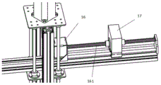
A mechanical arm is arranged on the fourth supporting plate 12, and the mechanical arm comprises a horizontally placed cross beam 33, a grabbing device arranged at one end of the cross beam and a counterweight device arranged at the other end of the cross beam; as shown in fig. 3, the counterweight device includes a third stepping motor 16, a second lead screw 161, and a counterweight 17, an output shaft of the third stepping motor 16 is connected to the second lead screw 161 through a coupling, and the second lead screw 161 passes through the counterweight through a threaded hole formed in the counterweight 17; the position of the counterweight 17 on the second screw 161 is driven by the third stepper motor 16, thus keeping the lever of the beam balanced.
As shown in fig. 1 and 4, the gripping device comprises a vertical beam 34, the middle part of the vertical beam 34 is fixedly connected with a cross beam 33, the tail end of the vertical beam 34 is fixedly provided with a second servo motor 18, the output shaft of the second servo motor 18 is vertically downward and is fixedly connected with a rotating frame 19 below the second servo motor through a coupling, and the rotating frame 19 is fixedly connected with a four-jaw disc 22 below the rotating frame through a screw rod; the structure of the four-claw disc 22 is shown in fig. 5, the tail end of each claw is in a U-shaped groove 221, a finger 20 is hinged in each U-shaped groove, the tail end of each finger 20 is provided with a palm 21, and a pressure sensor 23 is arranged in the surface opposite to the palm 21; a worm speed-reducing self-locking motor 24 is also arranged in the rotating frame 19, and an output shaft of the worm speed-reducing self-locking motor 24 is vertically downward and is connected with a third screw rod 25 through a coupling; a cross 26 is also arranged between the four-jaw disc 22 and the rotating frame 19, a feed screw nut is fixedly connected below the center of the cross 26, and a third feed screw 25 penetrates through the cross 26 and the feed screw nut; a double-ended U-slot connector 27 is hinged to each arm of the cross 26, the other end of the double-ended U-slot connector 27 is hinged to the top end of the finger 26, and the double-ended U-slot connector 27 is located directly above each jaw of the four-jaw plate. In this example, a total of four fingers and four palms are provided.
The device can be controlled to operate by SIMATIC S7-200 PLC, liquid crystal display screen, travel switch, relay, etc. The working principle is as follows: when a start command is clicked on the liquid crystal display screen, the stepping motors 2 and 3 can obtain an instruction, the stepping motors 2 and 3 are powered, and the moving frame 6 and the first supporting plate 9 which are fixedly connected with the stepping motors 2 and 3 through PU steel wire synchronous belts start to move; the upper end of a screw rod 13 penetrating through the fourth supporting plate is fixedly connected with a direct current motor 15 through a coupler, and the lower end of the screw rod 13 is connected with a bearing, so that the fourth supporting plate and a mechanical arm on the fourth supporting plate can easily realize the movement in the Z-axis direction; the stepping motors 2 and 3 are provided with stepping angles, the dial switches on the stepping motors can be adjusted to determine, and the stepping motors 2 and 3 rotate for several circles and rotate for several degrees, so that the displacement of the moving frame 6 and the first supporting plate 9 can be controlled, and accurate control is realized; because the mechanical gripper is set to be four fingers, pressure sensors are respectively arranged in the middle of the two corresponding surfaces, information acquired by the pressure sensors is processed and analyzed by a PLC (programmable logic controller), the worm speed reduction self-locking motor 24 rotates for a plurality of turns, meanwhile, the stepping motor 16 can simultaneously give instructions, the stepping motor 16 is fixedly connected with the screw rod 161 through a coupler, and the screw rod 161 is connected with the counterweight 17 through a screw rod nut. The second servo motor 18 can drive the fingers to rotate so as to adapt to the shape of the goods, and the counterweight 17 can be quickly and accurately pushed to a specified position while the goods are grabbed. When the heavy object is grabbed, the direct current motor 15 starts to work to drive the first screw rod 13 to rotate and enable the fourth supporting plate 12 to ascend rapidly, and when the fourth supporting plate 12 touches the travel switch, the direct current motor 15 stops working. The first servo motor 7 starts to operate to rotate the third support plate 11, and stops rotating when a certain angle is reached. The direct current motor 15 starts to work to enable the fourth supporting plate 12 to start to descend, the fourth supporting plate stops descending when the descending height reaches a specified value, and the worm speed reduction self-locking motor 24 is electrified to drive the third screw rod 25 to rotate so as to enable fingers and palms of the fingers to be loosened. The gripping and storing step principle is as described above and is fully understood by those skilled in the art.
The utility model can greatly improve the work efficiency and the work quality of product packing in industrial production, can effectively reduce the self-abrasion phenomenon of the mechanical arm caused by uneven stress in work through the intelligent detection balancing device, and the mechanical arm has the largest working radius and the smallest interference radius, has large working range and provides great flexibility in system design; the mechanical arm can work in different grabbing environments at the same time, and the counterweight mechanism of the mechanical arm can accurately and rapidly make balance judgment and execute counterweight, so that the problems of product packing quality, product stacking efficiency and the like in industrial production can be effectively solved.
Claims (5)
1. The utility model provides a balanced lifting arm device is examined to intelligence which characterized in that: the X-direction and Y-direction movable support device comprises a base, wherein a movable frame capable of moving along the X direction is arranged on the base, and a first support plate capable of moving along the Y direction is also arranged on the movable frame; a second support plate is arranged in parallel right above the first support plate, the first support plate and the second support plate are fixedly connected through a screw rod, and a third support plate is arranged in parallel right above the second support plate; a first servo motor is fixedly arranged above the center of the first supporting plate, and an output shaft of the first servo motor penetrates through the second supporting plate and is fixedly connected with the third supporting plate through a coupler; an upright post is fixedly arranged on the third support plate, the top of the upright post is fixedly connected with a fifth support plate, and a fourth support plate is arranged between the fifth support plate and the third support plate; a direct current motor is fixedly arranged on the fifth supporting plate, an output shaft of the direct current motor is vertically and downwards connected with a first screw rod through a coupler, and the lower end of the first screw rod is connected with the third supporting plate through a bearing seat; the center of the lower surface of the fourth supporting plate is fixedly connected with a screw nut, and the first screw rod penetrates through the fourth supporting plate and the screw nut; a mechanical arm is fixedly arranged on the fourth supporting plate and comprises a horizontally placed cross beam, a grabbing device arranged at one end of the cross beam and a counterweight device arranged at the other end of the cross beam; the first screw rod penetrates through the cross beam, and a pressure sensor is arranged on the grabbing device.
2. The intelligent balance lifting mechanical arm device as claimed in claim 1, wherein: a plurality of clamping wheels are fixedly arranged at the outer edge below the third supporting plate, each clamping wheel comprises a pair of upper wheels and lower wheels, and the upper wheels and the lower wheels clamp the upper surface and the lower surface of the second supporting plate; the third supporting plate drives the clamping wheel to rotate 360 degrees in a plane under the driving of the first servo motor.
3. The intelligent balance lifting mechanical arm device as claimed in claim 1, wherein: the counterweight device comprises a third stepping motor, a second screw rod and a counterweight block, wherein an output shaft of the third stepping motor is connected with the second screw rod through a coupler, and the second screw rod penetrates through the counterweight block through a threaded hole formed in the counterweight block; and the position of the balancing weight on the second screw rod is driven by the third stepping motor, so that the balance of the cross beam is kept.
4. The intelligent balance lifting mechanical arm device as claimed in claim 1, wherein: grabbing device is including erecting the roof beam, erects the middle part and crossbeam fixed connection of roof beam, and the terminal fixed mounting who erects the roof beam has second servo motor, and second servo motor's output shaft is vertical downwards, through shaft coupling and the swivel mount fixed connection of its below, and the swivel mount is connected with four claw dishes of below, and every claw end shape of four claw dishes is U type groove, and every U type inslot articulates there is the finger, and the finger end is provided with the palm, is provided with in the face that the palm is relative pressure sensor.
5. The intelligent balance lifting mechanical arm device as claimed in claim 4, wherein: a worm speed-reducing self-locking motor is further arranged in the rotating frame, an output shaft of the worm speed-reducing self-locking motor is vertically downward and is connected with a third screw rod through a coupling; a cross is further arranged between the four-jaw disc and the rotating frame, a feed screw nut is fixedly connected below the center of the cross, and a third feed screw penetrates through the cross and the feed screw nut; each arm of the cross is hinged with a double-head U-shaped groove connecting piece, the other end of each double-head U-shaped groove connecting piece is hinged with the top end of each finger, and each double-head U-shaped groove connecting piece is positioned right above each claw of the four-claw disc.
Priority Applications (1)
| Application Number | Priority Date | Filing Date | Title |
|---|---|---|---|
| CN201920967013.4U CN210061131U (en) | 2019-06-26 | 2019-06-26 | Intelligent detection balance crane mechanical arm device |
Applications Claiming Priority (1)
| Application Number | Priority Date | Filing Date | Title |
|---|---|---|---|
| CN201920967013.4U CN210061131U (en) | 2019-06-26 | 2019-06-26 | Intelligent detection balance crane mechanical arm device |
Publications (1)
| Publication Number | Publication Date |
|---|---|
| CN210061131U true CN210061131U (en) | 2020-02-14 |
Family
ID=69428569
Family Applications (1)
| Application Number | Title | Priority Date | Filing Date |
|---|---|---|---|
| CN201920967013.4U Expired - Fee Related CN210061131U (en) | 2019-06-26 | 2019-06-26 | Intelligent detection balance crane mechanical arm device |
Country Status (1)
| Country | Link |
|---|---|
| CN (1) | CN210061131U (en) |
Cited By (3)
| Publication number | Priority date | Publication date | Assignee | Title |
|---|---|---|---|---|
| CN110142752A (en) * | 2019-06-26 | 2019-08-20 | 安阳工学院 | A kind of intelligence inspection balance crane tool arm assembly |
| CN112978363A (en) * | 2021-03-25 | 2021-06-18 | 重庆途益物流有限公司 | Intelligent logistics control device with multi-directional adjustment function |
| CN115351816A (en) * | 2022-10-19 | 2022-11-18 | 沈阳工业大学 | Self-balancing mechanical arm |
-
2019
- 2019-06-26 CN CN201920967013.4U patent/CN210061131U/en not_active Expired - Fee Related
Cited By (4)
| Publication number | Priority date | Publication date | Assignee | Title |
|---|---|---|---|---|
| CN110142752A (en) * | 2019-06-26 | 2019-08-20 | 安阳工学院 | A kind of intelligence inspection balance crane tool arm assembly |
| CN110142752B (en) * | 2019-06-26 | 2023-12-12 | 安阳工学院 | Intelligent detection balance lifting mechanical arm device |
| CN112978363A (en) * | 2021-03-25 | 2021-06-18 | 重庆途益物流有限公司 | Intelligent logistics control device with multi-directional adjustment function |
| CN115351816A (en) * | 2022-10-19 | 2022-11-18 | 沈阳工业大学 | Self-balancing mechanical arm |
Similar Documents
| Publication | Publication Date | Title |
|---|---|---|
| CN110142752B (en) | Intelligent detection balance lifting mechanical arm device | |
| CN210061131U (en) | Intelligent detection balance crane mechanical arm device | |
| CN103010764B (en) | One parallel bar stacking machine robot | |
| CN100532026C (en) | Glass substrate transferring robot | |
| CN108527423A (en) | Structure adaptive manipulator grasping mechanism | |
| CN107020607A (en) | Wheel hub positioning table | |
| CN113070798B (en) | External surface finish machining equipment for honeycomb ceramic carrier and using method | |
| CN104924141A (en) | Wheel alignment device | |
| CN102642204A (en) | Alternating-current servo direct drive type series-parallel composite robot | |
| CN208826149U (en) | A kind of automation loading and unloading manipulator | |
| CN113375630A (en) | Detection apparatus suitable for industrial robot | |
| CN112357569A (en) | Material container handling robot system | |
| CN204221785U (en) | A kind of industrial robot | |
| CN102699896A (en) | Material separating rotating mechanical hand | |
| CN215359253U (en) | Vertical single crystal squaring machine of annular diamond wire | |
| CN209319773U (en) | A kind of three axis truss robot device of four station | |
| CN216442574U (en) | Truss manipulator for assembly platform | |
| CN2465926Y (en) | Aerated concrete NC cutter | |
| CN114102390A (en) | Automatic grinding system and grinding method for wind power hub | |
| CN112198154A (en) | Network transformer module detection and code disc system based on machine vision | |
| CN208467077U (en) | A kind of punching automation feeding line alignment table automatic regulating apparatus | |
| CN213796487U (en) | Sucking disc formula transport five-axis manipulator | |
| CN111469119A (en) | Special steel bar surface grinding robot based on parallel driving mechanism | |
| CN219819736U (en) | Single-upright-column rotary double-arm truss robot | |
| CN110280850A (en) | A kind of ZNC punch |
Legal Events
| Date | Code | Title | Description |
|---|---|---|---|
| GR01 | Patent grant | ||
| GR01 | Patent grant | ||
| CF01 | Termination of patent right due to non-payment of annual fee | ||
| CF01 | Termination of patent right due to non-payment of annual fee |
Granted publication date: 20200214 Termination date: 20200626 |