CN209997393U - energy-saving flue gas desulfurization tower - Google Patents
energy-saving flue gas desulfurization tower Download PDFInfo
- Publication number
- CN209997393U CN209997393U CN201920549488.1U CN201920549488U CN209997393U CN 209997393 U CN209997393 U CN 209997393U CN 201920549488 U CN201920549488 U CN 201920549488U CN 209997393 U CN209997393 U CN 209997393U
- Authority
- CN
- China
- Prior art keywords
- rotating
- flue gas
- desulfurization tower
- rotary
- rotating pump
- Prior art date
- Legal status (The legal status is an assumption and is not a legal conclusion. Google has not performed a legal analysis and makes no representation as to the accuracy of the status listed.)
- Active
Links
Images


Abstract
The utility model discloses an energy-saving flue gas desulfurization tower, including the desulfurizing tower shell, the exhanst gas outlet is installed on the top of desulfurizing tower shell, the internally mounted of desulfurizing tower shell has super absorbent resin, the defroster is installed to super absorbent resin's below, the smoke filtering net is installed to the below of defroster, the below of smoke filtering net is provided with the storehouse of admitting air, the below in storehouse of admitting air is provided with the oxidation pond, the internally mounted in storehouse of admitting air has the rotation axis, rotatory nozzle is installed in the outside of rotation axis, rotatory nozzle's bottom is provided with rotatory water spout, rotatory nozzle's side is provided with the flue gas entry, the internally mounted in oxidation pond has rotatory (mixing) shaft.
Description
Technical Field
The utility model relates to a desulfurizing tower technical field specifically is energy-saving flue gas desulfurization towers.
Background
With the rapid development of social economy, the desulfurizing tower is tower equipment for desulfurizing industrial waste gas, is widely applied to flue gas desulfurization in the domestic coal-fired industry, the desulfurizing tower can prevent sulfur-containing flue gas from being discharged to pollute the atmosphere, gas desulfurized by the desulfurizing tower is harmless to the environment and is environment-friendly, continuous improvement and improvement are carried out on the research of improving the energy saving performance of the flue gas desulfurizing tower, the existing flue gas desulfurizing tower has the defect of in use, and the energy consumption of the desulfurizing tower is high when the flue gas is subjected to layer-by-layer desulfurization treatment in the desulfurizing tower.
However, in the existing flue gas desulfurization, the efficiency of oxidizing air and water is low, and the oxidizing air injected into the circulated water is not uniform, so that the existing requirements are not met, and energy-saving flue gas desulfurization towers are proposed.
SUMMERY OF THE UTILITY MODEL
The utility model aims at providing energy-saving flue gas desulfurization towers to solve the oxidation air that proposes among the above-mentioned background art and the water oxidation's inefficiency, the inhomogeneous problem of oxidation air of the aquatic injection after the circulation.
For realizing the above-mentioned purpose, the utility model provides a energy-saving flue gas desulfurization towers, including the desulfurizing tower shell, the exhanst gas outlet is installed on the top of desulfurizing tower shell, the internally mounted of desulfurizing tower shell has super absorbent resin, the defroster is installed to super absorbent resin's below, the fume filter screen is installed to the below of defroster, the below of fume filter screen is provided with the storehouse of admitting air, the below of the storehouse of admitting air is provided with the oxidation pond, the internally mounted of storehouse of admitting air has the rotation axis, rotatory nozzle is installed in the outside of rotation axis, the bottom of rotatory nozzle is provided with rotatory water jet, the side of rotatory nozzle is provided with the flue gas entry, the internally mounted of oxidation pond has rotatory (mixing) shaft, the agitator is installed in the outside of rotatory (mixing) shaft, the outside installation solenoid valve of rotatory (mixing) end, the bearing is installed in the outside of end, the solenoid valve passes through the bearing and is connected with rotatory (mixing) shaft, the other end of solenoid valve installs oxidation air conduit, the surface mounting of desulfurizing tower shell has rotatory motor, and the bottom of the square circulation pump frame is installed through the bottom of the square circulation pump frame, the bottom of the circulation pump, the bottom of the square circulation pump frame is installed on the rotation shaft, the bottom of the square circulation pump, the bottom of the square circulation frame is installed the filter screen, the bottom of the rotary pump, the rotary pump is installed the rotary pump, the rotary pump is connected with the bottom of the rotary pump, the rotary pump is installed the bottom of the rotary.
Preferably, the number of the rotary nozzles is six, three rotary water spraying ports are arranged on the outer surface of each rotary nozzle, and the inclination angle of each rotary water spraying port is thirty degrees.
Preferably, the outer surface of the stirrer is provided with a stirrer air outlet, and the outer wall of the rotary stirring shaft is provided with a rotary stirring shaft air outlet.
Preferably, the filter screen is connected with the water outlet through a bolt.
Preferably, the internally mounted of flue gas filter screen has honeycomb electronic filter, the dead lever is all installed to the both sides of flue gas filter screen bottom, and the dead lever passes through bolted connection with the desulfurizing tower shell.
Preferably, the side of the electromagnetic valve is completely attached to the outer surface of the outer shell of the desulfurization tower, and the electromagnetic valve and the outer shell of the desulfurization tower are fixed through bolts.
Preferably, the top end of the base support is completely attached to the bottom surface of the outer shell of the desulfurizing tower, and the base support and the outer shell of the desulfurizing tower are fixed through welding.
Compared with the prior art, the beneficial effects of the utility model are that:
1. the utility model drives the rotary stirring shaft to rotate through the rotary motor, the rotary stirring shaft drives the stirrer to move, and the stirrer and the rotary stirring shaft are provided with air holes for releasing air, so that the oxidation air introduced into the oxidation air pipeline can be better combined with the wastewater to react in the moving process;
2. the utility model absorbs the moisture in the discharged gas through the super absorbent resin, thereby reducing the pollution of the gas;
3. the utility model discloses an inboard of outlet is installed the filter screen and can be stopped the oxide that contains sulphur in the oxidation pond, makes the flush fluid effect of circulation better.
Drawings
Fig. 1 is a schematic overall structure diagram of the present invention;
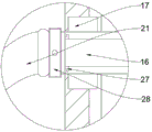
FIG. 2 is a schematic view of a partial structure of the rotary stirring shaft of the present invention;
fig. 3 is a schematic view of a partial structure of the rotary spraying device of the present invention;
fig. 4 is a schematic view of a partial structure of the oxidation air pipeline of the present invention.
In the figure, the device comprises a flue gas outlet 1, a desulfurizing tower shell 2, a high water absorption resin 3, a right-angle water pipe 4, a square spraying frame 5, a demister 6, a gas inlet bin 7, a filter screen 8, a waste bin , an oxidation pond 11, a flue gas filter screen 12, a base support 13, a rotary spray head 14, a flue gas inlet 15, a stirrer 16, a rotary stirring shaft 17, a bearing 18, a rotary motor 19, a water outlet 20, a circulating slurry pump 21, an oxidizing air pipeline 22, a circulating slurry pump base 23, a rotary stirring shaft outlet 24, a stirrer outlet 25, a rotating shaft 26, a rotary water spray nozzle 27, an annular limiting block 28 and an electromagnetic valve.
Detailed Description
The technical solutions in the embodiments of the present invention will be described clearly and completely with reference to the accompanying drawings in the embodiments of the present invention, and it is obvious that the described embodiments are only some embodiments, not all embodiments, of the present invention .
Referring to fig. 1-4, embodiments of the present invention provide an energy-saving flue gas desulfurization tower, including a desulfurization tower housing 2, a flue gas outlet 1 is installed at the top end of the desulfurization tower housing 2, a super absorbent resin 3 is installed inside the desulfurization tower housing 2, a demister 6 is installed below the super absorbent resin 3, a flue gas filter screen 11 is installed below the demister 6, effectively desulfurize the exhaust gas, an air inlet bin 7 is disposed below the flue gas filter screen 11, an oxidation tank 10 is disposed below the air inlet bin 7, a rotating shaft 25 is installed inside the air inlet bin 7, a rotary spray head 13 is installed outside the rotating shaft 25, a rotary water spray nozzle 26 is disposed at the bottom end of the rotary spray head 13, a flue gas inlet 14 is disposed at the side of the rotary spray head 13, a rotary stirring shaft 16 is installed inside the oxidation tank 10, an agitator 15 is installed outside the rotary stirring shaft 16, an electromagnetic valve 28 is installed outside the rotary stirring shaft 16, a bearing 17 is installed outside the end of the electromagnetic valve 28, the rotary stirring shaft 16 is connected to the rotary stirring shaft 16 through the bearing 17, another end of an oxidation air pipeline 21 is installed at the end of the desulfurization tower housing 2, an oxidation pump housing 2, an outer surface of the desulfurization tower housing 2, an oxidation pump 18 is installed outside a rotary stirring shaft 16, a rotary stirring shaft frame is installed outside a rotary stirring shaft frame, a rotary stirring shaft frame 19, a rotary stirring shaft frame is connected to a rotary stirring pump 20, a rotary stirring shaft frame 20, a rotary stirring pump 10, a rotary stirring pump base is installed outside a rotary stirring shaft frame which is installed on the rotary stirring pump 10, a rotary stirring shaft frame which is connected to a rotary stirring shaft frame, a rotary stirring.
, six rotary nozzles 13 are arranged, three rotary water spraying nozzles 26 are arranged on the outer surface of the rotary nozzle 13, the inclination angles of the rotary water spraying nozzles 26 are thirty degrees, the rotary water spraying nozzles 26 are matched with the inclination angles to spray flushing water, and the rotary nozzle 13 is rotated by the recoil force.
And , arranging an agitator air outlet 24 on the outer surface of the agitator 15, and arranging a rotary agitating shaft air outlet 23 on the outer wall of the rotary agitating shaft 16, so that the oxygen is more fully contacted with the water.
And , the filter screen 8 is connected with the water outlet 19 through a bolt, and the connection state is stable.
Step , the inside of the smoke filter screen 11 is provided with a honeycomb electronic filter, the two sides of the bottom end of the smoke filter screen 11 are provided with fixing rods, and the fixing rods are connected with the outer shell 2 of the desulfurizing tower through bolts, so that the connection state is stable.
And , completely attaching the side of the electromagnetic valve 28 to the outer surface of the desulfurizing tower shell 2, and fixing the electromagnetic valve 28 and the desulfurizing tower shell 2 through bolts to stabilize the state of the electromagnetic valve 28.
, the top of the base support 12 is completely attached to the bottom of the desulfurizing tower casing 2, and the base support 12 is fixed to the desulfurizing tower casing 2 by welding, so that the stability of the device is effectively improved.
When the device is used, a valve of a flue gas inlet 14 is opened, waste gas enters an air inlet bin 7 along the flue gas inlet 14, a circulating slurry pump 20 connected with a rotary spray head 13 is opened, the circulating slurry pump 20 enables water to pass through a right-angle water pipe 4, the water is enabled to be sprayed out from a rotary water spray port 26, the rotating shaft 25 is driven to rotate by recoil force generated by the sprayed water, the rotary water spray port 26 rotates during spraying, the water is enabled to be in full contact with particles in the waste gas, then the gas passes through a flue gas filter screen 11, smaller particles in the waste gas are filtered and removed, the gas rises again to pass through a demister 6, mist in the gas is removed, finally the gas removes excessive water in the gas through a high-hydroscopicity resin 3, the gas is discharged from a flue gas outlet 1, three circulating slurry pumps 20 connected with a square spraying frame 5 are opened, the water is sprayed out from the square spraying frame 5 through the right-angle water pipe 4, impurities on the demister 6 and the flue gas filter screen 11 are washed away by the sprayed water, the impurities fall into an oxidation pond 10, an electromagnetic valve 28 is opened, oxidation air pipeline 21 is enabled to pass through a rotary exhaust water outlet 16, impurities discharge port 23, impurities discharge water outlet 23 is enabled to be fully discharged from a rotary reaction blocking filter shaft 19, impurities discharging water outlet 23 is enabled to be fully connected with a rotary reaction blocking filter shaft 19, and a rotary reaction water blocking filter shaft 19, and a rotary reaction tank, impurities blocking device, impurities blocking reaction water discharging tank is enabled to be fully discharged in a rotary reaction tank 10, and.
It will thus be seen that the present invention is illustrative and not restrictive, and the scope of the invention is defined by the appended claims rather than by the foregoing description, and all changes which come within the meaning and range of equivalency of the claims are therefore intended to be embraced therein.
Claims (7)
- The energy-saving flue gas desulfurization tower comprises a desulfurization tower shell (2) and is characterized in that a flue gas outlet (1) is installed at the top end of the desulfurization tower shell (2), super absorbent resin (3) is installed inside the desulfurization tower shell (2), a demister (6) is installed below the super absorbent resin (3), a flue gas filter screen (11) is installed below the demister (6), an air inlet bin (7) is arranged below the flue gas filter screen (11), an oxidation pond (10) is arranged below the air inlet bin (7), a rotating shaft (25) is installed inside the air inlet bin (7), a rotating spray head (13) is installed outside the rotating shaft (25), a rotating water spray nozzle (26) is arranged at the bottom end of the rotating spray head (13), a flue gas inlet (14) is arranged on the side of the rotating spray head (13), a rotating stirring shaft (16) is installed inside the oxidation pond (10), a stirrer (15) is installed outside the rotating stirring shaft (16), a rotary stirring shaft (16) is installed outside the rotating stirring shaft (16), a rotary slurry pump (16) is installed outside a rotating shaft (16), a rotating pump (16) is installed outside a rotating shaft pump (16) and a rotating slurry pump frame (18) is installed on a rotating shaft (18) and a rotating pump support (18), a rotating pump (18) and a rotating pump (16) which is connected with a rotating pump (18) and a rotating pump support (18) and a rotating pump support (16), the rotating pump support (18) and a rotating pump (18) which is installed outside, the rotating pump support (18) and a rotating pump (16), the rotating pump support (18) is connected with a rotating pump support (18) and a rotating pump support (18) of the rotating pump support (17), the rotating pump support (16), the rotating pump support (18) and a rotating pump support (18) are installed on the rotating pump support (18) and a rotating pump (18), the rotating pump support (18), the rotating pump (17), the rotating pump (18) and a rotating pump support (18) are installed on the rotating pump support (.
- 2. The energy-saving flue gas desulfurization tower of claim 1, wherein the number of the rotary nozzles (13) is six, the outer surface of the rotary nozzle (13) is provided with three rotary water injection ports (26), and the inclination angle of the rotary water injection ports (26) is thirty degrees.
- 3. The energy-saving flue gas desulfurization tower of claim 1, wherein the outer surface of the stirrer (15) is provided with a stirrer air outlet (24), and the outer wall of the rotary stirring shaft (16) is provided with a rotary stirring shaft air outlet (23).
- 4. The energy-saving flue gas desulfurization tower of claim 1, wherein the filter screen (8) is connected with the water outlet (19) by bolts.
- 5. The energy-saving flue gas desulfurization tower of claim 1, wherein the flue gas filter screen (11) is internally provided with a honeycomb electronic filter, and fixing rods are respectively arranged at two sides of the bottom end of the flue gas filter screen (11) and are connected with the desulfurization tower shell (2) through bolts.
- 6. The energy-saving flue gas desulfurization tower of claim 1, wherein the side of the solenoid valve (28) is fully attached to the outer surface of the desulfurization tower housing (2), and the solenoid valve (28) is fixed to the desulfurization tower housing (2) by bolts.
- 7. The kinds of energy-saving flue gas desulfurization towers of claim 1, wherein the top end of the base support (12) is completely attached to the bottom surface of the outer shell (2) of the desulfurization tower, and the base support (12) and the outer shell (2) of the desulfurization tower are fixed by welding.
Priority Applications (1)
| Application Number | Priority Date | Filing Date | Title |
|---|---|---|---|
| CN201920549488.1U CN209997393U (en) | 2019-04-22 | 2019-04-22 | energy-saving flue gas desulfurization tower |
Applications Claiming Priority (1)
| Application Number | Priority Date | Filing Date | Title |
|---|---|---|---|
| CN201920549488.1U CN209997393U (en) | 2019-04-22 | 2019-04-22 | energy-saving flue gas desulfurization tower |
Publications (1)
| Publication Number | Publication Date |
|---|---|
| CN209997393U true CN209997393U (en) | 2020-01-31 |
Family
ID=69304492
Family Applications (1)
| Application Number | Title | Priority Date | Filing Date |
|---|---|---|---|
| CN201920549488.1U Active CN209997393U (en) | 2019-04-22 | 2019-04-22 | energy-saving flue gas desulfurization tower |
Country Status (1)
| Country | Link |
|---|---|
| CN (1) | CN209997393U (en) |
Cited By (5)
| Publication number | Priority date | Publication date | Assignee | Title |
|---|---|---|---|---|
| CN112426852A (en) * | 2020-12-18 | 2021-03-02 | 华能秦煤瑞金发电有限责任公司 | Flue gas desulfurization device for coal-fired power plant |
| CN112870886A (en) * | 2021-01-16 | 2021-06-01 | 张鹏 | Spraying mechanism-based dust removal device for electrical engineering and use method thereof |
| CN113368682A (en) * | 2021-06-18 | 2021-09-10 | 武汉龙龟环保科技有限公司 | Flue gas purification treatment process |
| CN114733296A (en) * | 2022-04-25 | 2022-07-12 | 成都剀瑞环保工程有限公司 | Industrial flue gas environmental protection treatment facility |
| CN115055046A (en) * | 2022-06-15 | 2022-09-16 | 青岛格林特环保设备股份有限公司 | A smoke and dust denitration sulphur removal environment-friendly device for environmental pollution administers |
-
2019
- 2019-04-22 CN CN201920549488.1U patent/CN209997393U/en active Active
Cited By (6)
| Publication number | Priority date | Publication date | Assignee | Title |
|---|---|---|---|---|
| CN112426852A (en) * | 2020-12-18 | 2021-03-02 | 华能秦煤瑞金发电有限责任公司 | Flue gas desulfurization device for coal-fired power plant |
| CN112870886A (en) * | 2021-01-16 | 2021-06-01 | 张鹏 | Spraying mechanism-based dust removal device for electrical engineering and use method thereof |
| CN112870886B (en) * | 2021-01-16 | 2022-07-22 | 广东粤湛环保科技有限公司 | Spraying mechanism-based dust removal device for electrical engineering and use method thereof |
| CN113368682A (en) * | 2021-06-18 | 2021-09-10 | 武汉龙龟环保科技有限公司 | Flue gas purification treatment process |
| CN114733296A (en) * | 2022-04-25 | 2022-07-12 | 成都剀瑞环保工程有限公司 | Industrial flue gas environmental protection treatment facility |
| CN115055046A (en) * | 2022-06-15 | 2022-09-16 | 青岛格林特环保设备股份有限公司 | A smoke and dust denitration sulphur removal environment-friendly device for environmental pollution administers |
Similar Documents
| Publication | Publication Date | Title |
|---|---|---|
| CN209997393U (en) | energy-saving flue gas desulfurization tower | |
| CN107198945B (en) | Energy-saving environment-friendly desulfurization denitrification demercuration device for power plant | |
| CN211098372U (en) | Efficient flue gas desulfurization tower | |
| CN212039560U (en) | Waste gas treatment equipment | |
| CN104399367A (en) | Smoke washing device with scaling-shaped hole plate | |
| CN111001271A (en) | Small-size washing tower is used in lithium hexafluorophosphate production | |
| CN101298022B (en) | High-pressure fine water mist desulfurized dust collector with front-located dry precipitator and using method thereof | |
| CN201389423Y (en) | Flue gas desulphurization dust removing tower for coal burning boiler | |
| CN212167039U (en) | Novel high-pressure gas-liquid mixed waste gas purification treatment device | |
| CN211098371U (en) | Spray even desulfurizing tower | |
| CN211098374U (en) | High-efficient desulfurizing tower | |
| CN204320092U (en) | A kind of flue gas washing mechanism with convergent-divergent shape orifice plate | |
| CN201384922Y (en) | Spiral type vertical sieve plate jet bubbling desulfurization dust absorbing tower | |
| CN205570070U (en) | Compound desulphurization unit of ammonia process based on ultra -clean discharges | |
| CN202715350U (en) | Wet desulfurization adsorption tower with multi-effect turbulence system | |
| CN211098370U (en) | Novel spray desulfurizing tower | |
| CN212974565U (en) | Environment-friendly whirling water treatment spray tower | |
| CN109806753B (en) | Reduction circulation desulfurization device and desulfurization method | |
| CN206715649U (en) | A kind of house exhaust processing equipment of high-efficiency environment friendly | |
| CN101518716A (en) | Helical-type vertical sieve tray injection bubbling desulfurization and dedusting absorption tower | |
| CN217247967U (en) | Coal-fired flue gas desulfurization and mercury removal device | |
| CN211635744U (en) | Waste gas treatment equipment | |
| CN217855480U (en) | Polyurethane prepolymer exhaust treatment device | |
| CN206881385U (en) | Ship tail gas PM2.5 removal devices | |
| CN108339376B (en) | Centrifugal smoke purifier and smoke purifying method thereof |
Legal Events
| Date | Code | Title | Description |
|---|---|---|---|
| GR01 | Patent grant | ||
| GR01 | Patent grant |