CN209957212U - Lifting appliance and lifting system for mounting component under beam - Google Patents
Lifting appliance and lifting system for mounting component under beam Download PDFInfo
- Publication number
- CN209957212U CN209957212U CN201920465675.1U CN201920465675U CN209957212U CN 209957212 U CN209957212 U CN 209957212U CN 201920465675 U CN201920465675 U CN 201920465675U CN 209957212 U CN209957212 U CN 209957212U
- Authority
- CN
- China
- Prior art keywords
- lifting
- lifting lug
- welded
- hoisting
- lug
- Prior art date
- Legal status (The legal status is an assumption and is not a legal conclusion. Google has not performed a legal analysis and makes no representation as to the accuracy of the status listed.)
- Expired - Fee Related
Links
- 229910000831 Steel Inorganic materials 0.000 claims abstract description 49
- 239000010959 steel Substances 0.000 claims abstract description 49
- 230000003014 reinforcing effect Effects 0.000 claims abstract description 37
- 238000009434 installation Methods 0.000 claims description 21
- 238000003466 welding Methods 0.000 claims description 3
- 238000000034 method Methods 0.000 abstract description 20
- 230000007704 transition Effects 0.000 abstract description 3
- 238000009435 building construction Methods 0.000 abstract 1
- 238000006243 chemical reaction Methods 0.000 description 4
- 238000010276 construction Methods 0.000 description 4
- 238000011900 installation process Methods 0.000 description 3
- 230000009286 beneficial effect Effects 0.000 description 1
- 230000000694 effects Effects 0.000 description 1
- 230000002349 favourable effect Effects 0.000 description 1
Images


Landscapes
- Conveying And Assembling Of Building Elements In Situ (AREA)
Abstract
A lifting appliance for mounting a member under a beam and a lifting system relate to the field of building construction, and comprise a lifting frame of an equilateral triangle with an obtuse angle at the vertex angle, a reinforcing rod piece welded on the longitudinal axis of one side surface of the lifting frame, a first lower lifting lug welded on one side of the bottom surface of the lifting frame, a second lower lifting lug welded on the other side of the bottom surface of the lifting frame and an upper lifting lug welded on the top surface of the lifting frame; the hoisting system for installing the hoisting tool by applying the under-beam member comprises a hoisting device, the hoisting tool hoisted under the hoisting device, a member arranged on one side of the bottom surface of the hoisting tool and a counterweight arranged on the other side of the bottom surface of the hoisting tool; the rotation angle i of the section steel bottom rod of the hanger before and after the unloading of the member is less than 60 degrees. The utility model provides a current hoist uninstallation in-process state transition range is great after the component takes one's place, has the structure to collide easily with the top, all has the problem of great potential safety hazard to structure, machinery, operation personnel.
Description
Technical Field
The utility model relates to a construction field, especially a member installation hoist and mount system under roof beam.
Background
With the rapid development of steel structure buildings in recent years, the application of steel structures in large buildings is more and more extensive, and the structural forms of the steel structures are more and more diversified and complicated. In some buildings with complex structures, due to the installation sequence, the installation process and other reasons, the problem that the embedded rod piece is positioned in the frame and cannot be installed by using a conventional hoisting mode exists. To such installation problems, the prior art often uses a linear spreader to accomplish the installation under the beam of the component. When the lifting appliance in the form is used, the lower beam of the member can be in place, but the unloading process of the lifting appliance can be gradually changed from a horizontal state to a completely vertical state after the member is in place, the state conversion amplitude is large, the unloading end is likely to collide with the existing structure above due to the overlarge tilting angle in the conversion process, and great potential safety hazards are caused to the structure, machinery and operators. Among the prior art of construction, there are more inconvenience and risk in the hoist and mount of member under the roof beam: because the conventional hoisting mode can not enable the under-beam member to be smoothly in place, the in-line lifting appliance is often adopted to realize the under-beam in place in the existing installation process. The component takes one place the back and need unload component one end, because the structural feature of a straight line hoist, the uninstallation in-process hoist will be changed into vertical state by the horizontality gradually, and the range of conversion reaches about 90 in the uninstallation in-process, takes place uncontrollable collision with the mounted structure of component top easily, has direct harm effect to overall structure, and the high altitude that the collision probably arouses falls the thing etc. and risk also has very big potential safety hazard to hoist and mount machinery and relevant operation personnel. On the other hand, the larger the conversion amplitude of the unloading process is, the higher the requirement on the matching degree of the hoisting machinery is, the angle needs to be adjusted continuously by slow operation, so that the whole installation progress is slow, and the efficiency is low.
SUMMERY OF THE UTILITY MODEL
The utility model aims at providing a member installation hoist and mount system under roof beam, it is great to solve present hoist uninstallation in-process state transition range after the member takes one's place, has had the structure to collide easily with the top, all has the problem of great potential safety hazard to structure, machinery, operation personnel.
In order to achieve the above purpose, the utility model adopts the following technical scheme:
a lifting appliance for mounting a member under a beam comprises a lifting frame of an equilateral triangle with an obtuse angle at the vertex angle, a reinforcing rod piece welded on the longitudinal axis of one side surface of the lifting frame, a first lower lifting lug welded on one side of the bottom surface of the lifting frame, a second lower lifting lug welded on the other side of the bottom surface of the lifting frame and an upper lifting lug welded on the top surface of the lifting frame;
the hanger is formed by welding H-shaped steel and comprises a horizontal steel bottom rod and steel inclined rods welded at two ends of the top surface of the steel bottom rod; the top edges of the lower flange plates of the two steel inclined rods are butted, and the top edges of the upper flange plates are connected through a horizontal connecting plate;
a vertical first reinforcing rib is arranged between the top edges of the lower flange plates of the two profiled steel diagonal rods and the lower surface of the connecting plate, a vertical second reinforcing rib is arranged between the lower flange plates of the two profiled steel diagonal rods and the profiled steel bottom rod, a vertical third reinforcing rib is arranged between the upper flange plates of the two profiled steel diagonal rods and the profiled steel bottom rod, and vertical fourth reinforcing ribs are arranged between the upper flange plates and the lower flange plates of the profiled steel bottom rod at intervals;
vertical first connecting ribs are arranged on the upper surface of the connecting plate at intervals, and two vertical second connecting ribs are arranged on two sides of the lower flange plate of the profile steel bottom rod respectively;
the upper lifting lug is an arc-shaped plate with a horizontal bottom surface, a first lifting hole is formed in the middle of the upper lifting lug, the bottom surface of the upper lifting lug is welded with the top surface of the connecting plate, and one side surface of the upper lifting lug is welded with the first connecting rib;
the first lower lifting lug is an arc-shaped plate with a horizontal bottom surface, a second lifting hole is formed in the middle of the first lower lifting lug, the bottom surface of the first lower lifting lug is welded with a lower flange plate of the section steel bottom rod, and one side surface of the first lower lifting lug is welded with the second connecting rib; the structure of the second lower lifting lug is the same as that of the first lower lifting lug;
the thickness of the upper lifting lug and the thickness of the first lower lifting lug are both 20 mm.
The thicknesses of the first reinforcing rib, the second reinforcing rib, the third reinforcing rib, the fourth reinforcing rib, the first connecting rib and the second connecting rib are all 10 mm.
The hoisting system for installing the hoisting tool by applying the under-beam member comprises a hoisting device, the hoisting tool hoisted under the hoisting device, a member arranged on one side of the bottom surface of the hoisting tool and a counterweight arranged on the other side of the bottom surface of the hoisting tool;
the upper lifting lug of the lifting appliance is connected with the lifting device through an upper pulling rope, the first lower lifting lug on one side is connected with the component through a first lower pulling rope, and the second lower lifting lug on the other side is connected with the counterweight through a second lower pulling rope;
the rotation angle i of the section steel bottom rod of the hanger before and after the unloading of the member is less than 60 degrees.
The counterweight part consists of standard counterweight blocks;
the weight of the weight is the same as the weight of the member.
The lifting capacity of the lifting device is not less than the sum of the weights of the member and the counterweight.
Compared with the prior art the utility model has the following characteristics and beneficial effect:
the utility model relates to a triangle-shaped hoist replaces current sharp shape hoist that appears, realize the installation of component under the roof beam, according to size and the angle of the accurate calculation hoist of on-the-spot actual conditions, adopt triangle-shaped hoist to realize taking one's place installation and the uninstallation of hoist of component, the last lug and the hoisting accessory of hoist are connected, first lug is connected with treating the installation component, lug and the weight assorted counterweight of treating the installation component are connected under the second, the component is installed and is unloaded the component after taking one's place, the uninstallation process is adjusted gradually by hoisting accessory and is gone up the lug position and realize, the uninstallation is accomplished when lug and second are in the vertical state under last lug, first lug is loose the hook, the installation of component is accomplished.
The utility model solves the problem that the form change amplitude is too large in the unloading process of the lifting appliance, realizes the small amplitude and collision-free unloading lifting appliance in the installation process of the component under the beam, and the lifting appliance can be repeatedly and circularly used for the installation of the same type of components, is convenient to disassemble and install in the use process, and the smaller form change amplitude is favorable for improving the installation efficiency and reducing the construction cost; the problem of when using traditional in-line hoist to carry out under-beam component installation, the hoist uninstallation in-process state transition range is too big and the component collision takes place easily is solved, the while is solved the uninstallation in-process hoisting accessory cooperation process complicated, the coordination difficulty problem, has improved installation effectiveness.
And simultaneously, the utility model discloses the design of triangle-shaped hoist, the component installation under the roof beam under the adaptable multiple condition, the assembling process is simple and convenient, and installation uninstallation process security is high.
The utility model discloses but wide application in the uninstallation in-process of component under various construction operating mode.
Drawings
The present invention will be described in further detail with reference to the accompanying drawings.
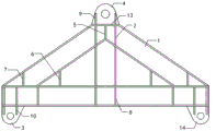
Fig. 1 is a schematic structural view of a spreader.
Fig. 2 is a schematic view of the assembly of the spreader during hoisting.
Figure 3 is a schematic view of the components in position during hoisting.
Fig. 4 is a schematic view of the unloading of the spreader during the hoisting process.
Fig. 5 is a schematic view of the unloading completion of the lifting appliance in the lifting process.
Reference numerals: the lifting device comprises a lifting frame 1, a reinforcing rod 2, a first lower lifting lug 3, an upper lifting lug 4, a first reinforcing rib 5, a second reinforcing rib 6, a third reinforcing rib 7, a fourth reinforcing rib 8, a first connecting rib 9, a second connecting rib 10, a member 11, a counterweight 12, a connecting plate 13 and a second lower lifting lug 14.
Detailed Description
Referring to fig. 1, the utility model provides a lifting appliance and a lifting system for mounting a member under a beam, the lifting appliance for mounting a member under a beam comprises a hanger 1 with an equilateral triangle with an obtuse angle at the vertex angle, a reinforcing rod 2 welded on the longitudinal axis of one side of the hanger 1, a first lower lifting lug 3 welded on one side of the bottom surface of the hanger 1, a second lower lifting lug 14 welded on the other side of the bottom surface of the hanger 1 and an upper lifting lug 4 welded on the top surface of the hanger 1; the hanger 1 is formed by welding H-shaped steel, the strength of the H-shaped steel meets the lifting safety requirement, the specific size is determined by the actual field condition, and the hanger comprises a horizontal steel bottom rod and steel inclined rods welded at two ends of the top surface of the steel bottom rod; in the embodiment, the length of the profiled steel bottom rod is 1500mm, and the length of the profiled steel inclined rod is 789 mm; the top edges of the lower flange plates of the two steel inclined rods are butted, and the top edges of the upper flange plates are connected through a horizontal connecting plate 13; a vertical first reinforcing rib 5 is arranged between the top edges of the lower flange plates of the two profile steel diagonal rods and the lower surface of the connecting plate 13, a vertical second reinforcing rib 6 is arranged between the lower flange plates of the two profile steel diagonal rods and the profile steel bottom rod, a vertical third reinforcing rib 7 is arranged between the upper flange plates of the two profile steel diagonal rods and the profile steel bottom rod, and vertical fourth reinforcing ribs 8 are arranged between the upper flange plates and the lower flange plates of the profile steel bottom rod at intervals; vertical first connecting ribs 9 are arranged on the upper surface of the connecting plate 13 at intervals, and two vertical second connecting ribs 10 are arranged on two sides of the lower flange plate of the profile steel bottom rod respectively; the upper lifting lug 4 is an arc-shaped plate with a horizontal bottom surface, a first lifting hole is formed in the middle of the upper lifting lug 4, the bottom surface of the upper lifting lug 4 is welded with the top surface of the connecting plate 13, and one side surface of the upper lifting lug is welded with the first connecting rib 9; the first lower lifting lug 3 is an arc-shaped plate with a horizontal bottom surface, a second lifting hole is formed in the middle of the first lower lifting lug, the bottom surface of the first lower lifting lug 3 is welded with a lower flange plate of the section steel bottom rod, and one side surface of the first lower lifting lug is welded with the second connecting rib 10; the second lower lifting lug 14 has the same structure as the first lower lifting lug 3; the thicknesses of the upper lifting lug 4 and the first lower lifting lug 3 are both 20 mm; the thicknesses of the first reinforcing rib, the second reinforcing rib, the third reinforcing rib, the fourth reinforcing rib, the first connecting rib and the second connecting rib are all 10 mm.
The hoisting system for installing the hoisting tool by applying the member under the beam comprises a hoisting device, the hoisting tool hoisted under the hoisting device, a member 11 arranged on one side of the bottom surface of the hoisting tool and a counterweight 12 arranged on the other side of the bottom surface of the hoisting tool; in the embodiment, the weight of the member 11 is 7t, the weight of the counterweight 12 is 5t, the hoisting device comprises hoisting machinery and a sling, namely an upper pulling rope, the sling meets the requirement of the member on hoisting weight and has safe storage meeting the specification, and the sling is intact; the upper lifting lug 4 of the lifting appliance is connected with the lifting device through an upper pulling rope, the first lower lifting lug 3 on one side is connected with the member 11 through a first lower pulling rope, and the second lower lifting lug 14 on the other side is connected with the counterweight 12 through a second lower pulling rope; the rotating angle i of a section steel bottom rod of the hanger 1 of the hanger before and after unloading of the member is 52 degrees; the counterweight part consists of standard counterweight blocks; the weight of the counterweight is the same as that of the component to be mounted and is matched with that of the component to be mounted; the lifting capacity of the lifting device is not less than the sum of the weights of the member and the counterweight, and the lifting safety requirement is met.
The utility model discloses a working process:
the method comprises the following steps: and selecting a hoisting device according to the size and weight of the member to be installed, and determining the specification and size of the hoisting device.
Step two: and respectively carrying out strength checking calculation on the upper lifting lug, the first lower lifting lug, the second lower lifting lug, the first reinforcing rib, the second reinforcing rib, the third reinforcing rib, the fourth reinforcing rib, the first connecting rib, the second connecting rib and the upper traction rope, and carrying out strength calculation on the lifting working condition of the triangular lifting appliance.
Step three: and determining the position of the crane, connecting the component to a first lower lifting lug of the lifting appliance through a first lower traction rope, connecting a counterweight matched with the component to a second lower lifting lug of the lifting appliance through a second traction rope, and completing the assembly of the triangular lifting appliance as required.
Step four: and slowly lifting the component and adjusting the angle position through the lifting machine, keeping the balance and stability of the lifting tool, and completing the component installation when the component is lifted to the position to be installed below the beam.
Step five: and unloading the member after the member is installed, slowly descending the counterweight part and adjusting the angle position of the upper lifting lug of the lifting appliance through the lifting machine, and finishing unloading when the upper lifting lug and the second lower lifting lug are in a vertical state.
And step six, the first lower lifting lug is loosened, and the installation of the lower beam member is completed.
Claims (6)
1. The utility model provides a member installation hoist under roof beam which characterized in that: the lifting device comprises a lifting frame (1) of an equilateral triangle with an obtuse angle at the vertex angle, a reinforcing rod piece (2) welded on the longitudinal axis of one side surface of the lifting frame (1), a first lower lifting lug (3) welded on one side of the bottom surface of the lifting frame (1), a second lower lifting lug (14) welded on the other side of the bottom surface of the lifting frame (1) and an upper lifting lug (4) welded on the top surface of the lifting frame (1);
the hanger (1) is formed by welding H-shaped steel and comprises a horizontal shaped steel bottom rod and shaped steel inclined rods welded at two ends of the top surface of the shaped steel bottom rod; the top edges of the lower flange plates of the two steel inclined rods are butted, and the top edges of the upper flange plates are connected through a horizontal connecting plate (13);
a vertical first reinforcing rib (5) is arranged between the top edges of the lower flange plates of the two profile steel diagonal rods and the lower surface of the connecting plate (13), a vertical second reinforcing rib (6) is arranged between the lower flange plates of the two profile steel diagonal rods and the profile steel bottom rod, a vertical third reinforcing rib (7) is arranged between the upper flange plates of the two profile steel diagonal rods and the profile steel bottom rod, and vertical fourth reinforcing ribs (8) are arranged between the upper flange plates and the lower flange plates of the profile steel bottom rod at intervals;
vertical first connecting ribs (9) are arranged on the upper surface of the connecting plate (13) at intervals, and two vertical second connecting ribs (10) are respectively arranged on two sides of the lower flange plate of the profile steel bottom rod;
the upper lifting lug (4) is an arc-shaped plate with a horizontal bottom surface, a first lifting hole is formed in the middle of the upper lifting lug, the bottom surface of the upper lifting lug (4) is welded with the top surface of the connecting plate (13), and one side surface of the upper lifting lug is welded with the first connecting rib (9);
the first lower lifting lug (3) is an arc-shaped plate with a horizontal bottom surface, a second lifting hole is formed in the middle of the first lower lifting lug, the bottom surface of the first lower lifting lug (3) is welded with a lower flange plate of the profile steel bottom rod, and one side surface of the first lower lifting lug is welded with the second connecting rib (10); the structure of the second lower lifting lug (14) is the same as that of the first lower lifting lug (3).
2. The underbeam member mounting hanger of claim 1, wherein: the thicknesses of the upper lifting lug (4) and the first lower lifting lug (3) are both 20 mm.
3. The underbeam member mounting hanger of claim 1, wherein: the thicknesses of the first reinforcing rib, the second reinforcing rib, the third reinforcing rib, the fourth reinforcing rib, the first connecting rib and the second connecting rib are all 10 mm.
4. The hoisting system using the underbeam member installation hanger of claim 1, wherein: comprises a hoisting device, a lifting appliance hoisted below the hoisting device, a member (11) arranged on one side of the bottom surface of the lifting appliance and a counterweight (12) arranged on the other side of the bottom surface of the lifting appliance;
an upper lifting lug (4) of the lifting appliance is connected with the lifting device through an upper pulling rope, a first lower lifting lug (3) on one side is connected with a member (11) through a first lower pulling rope, and a second lower lifting lug (14) on the other side is connected with a counterweight (12) through a second lower pulling rope;
the rotation angle i of a section steel bottom rod of a hanger (1) of the lifting appliance before and after the unloading of the member is less than 60 degrees.
5. Hoisting system according to claim 4, wherein: the counterweight part consists of standard counterweight blocks;
the weight of the weight is the same as the weight of the member.
6. Hoisting system according to claim 5, characterized in that: the lifting capacity of the lifting device is not less than the sum of the weights of the member and the counterweight.
Priority Applications (1)
| Application Number | Priority Date | Filing Date | Title |
|---|---|---|---|
| CN201920465675.1U CN209957212U (en) | 2019-04-09 | 2019-04-09 | Lifting appliance and lifting system for mounting component under beam |
Applications Claiming Priority (1)
| Application Number | Priority Date | Filing Date | Title |
|---|---|---|---|
| CN201920465675.1U CN209957212U (en) | 2019-04-09 | 2019-04-09 | Lifting appliance and lifting system for mounting component under beam |
Publications (1)
| Publication Number | Publication Date |
|---|---|
| CN209957212U true CN209957212U (en) | 2020-01-17 |
Family
ID=69242063
Family Applications (1)
| Application Number | Title | Priority Date | Filing Date |
|---|---|---|---|
| CN201920465675.1U Expired - Fee Related CN209957212U (en) | 2019-04-09 | 2019-04-09 | Lifting appliance and lifting system for mounting component under beam |
Country Status (1)
| Country | Link |
|---|---|
| CN (1) | CN209957212U (en) |
Cited By (1)
| Publication number | Priority date | Publication date | Assignee | Title |
|---|---|---|---|---|
| CN113086827A (en) * | 2021-04-02 | 2021-07-09 | 山东省公路桥梁建设有限公司 | Lifting appliance system for transporting beam under beam and lifting method |
-
2019
- 2019-04-09 CN CN201920465675.1U patent/CN209957212U/en not_active Expired - Fee Related
Cited By (1)
| Publication number | Priority date | Publication date | Assignee | Title |
|---|---|---|---|---|
| CN113086827A (en) * | 2021-04-02 | 2021-07-09 | 山东省公路桥梁建设有限公司 | Lifting appliance system for transporting beam under beam and lifting method |
Similar Documents
| Publication | Publication Date | Title |
|---|---|---|
| CN109081247A (en) | A kind of hanging method of vestibule large-span steel girder | |
| CN102635225A (en) | Equipment hoisting platform and method for super high-rise buildings | |
| CN209957212U (en) | Lifting appliance and lifting system for mounting component under beam | |
| CN201762035U (en) | Simple crane movable arm | |
| CN211470599U (en) | Auxiliary carrying pole beam for hoisting | |
| CN210908618U (en) | Turnover device for assembling H-shaped steel | |
| CN208166361U (en) | A kind of overlength light-weight metal roof boarding lifting attachment device | |
| CN207511723U (en) | A kind of flat arm tower crane supporting beam transporting device of new construction inner climbing type | |
| CN206569904U (en) | A kind of suspender for lifting steel plate | |
| CN210658056U (en) | Bridge steel stand hoist and mount device of turning | |
| CN210340141U (en) | House building engineering lifting device | |
| CN207209840U (en) | A kind of Multifunctional suspension bracket | |
| CN106869508B (en) | A kind of rotation lifting of assembled architecture steel box column is welded and fixed mounting process in place | |
| CN206580444U (en) | A kind of urban construction building prefabricated components hanging apparatus | |
| CN212475780U (en) | Counter weight formula lifting device | |
| CN217458557U (en) | Attachment structure of main building tower crane | |
| CN219279306U (en) | Single-machine lifting ground wall-connected reinforcement cage device in narrow space | |
| CN212450267U (en) | Large-scale PC component of assembled installation lifts by crane and turns over board frock equipment | |
| CN214692867U (en) | Balance hoisting structure of gantry crane | |
| CN218841482U (en) | Pipeline lifting device for construction | |
| CN209702229U (en) | Flooring construction tower crane turns device for hoisting | |
| CN212639768U (en) | Pipeline unloading device | |
| CN213569108U (en) | Precast beam template hoist and mount system | |
| CN217947344U (en) | Prefabricated component lifting device | |
| CN220165620U (en) | Simple and easy hoist device of pit shaft |
Legal Events
| Date | Code | Title | Description |
|---|---|---|---|
| GR01 | Patent grant | ||
| GR01 | Patent grant | ||
| CF01 | Termination of patent right due to non-payment of annual fee |
Granted publication date: 20200117 |