CN209954303U - Horizontal single-side boring combined machine tool - Google Patents
Horizontal single-side boring combined machine tool Download PDFInfo
- Publication number
- CN209954303U CN209954303U CN201920274754.4U CN201920274754U CN209954303U CN 209954303 U CN209954303 U CN 209954303U CN 201920274754 U CN201920274754 U CN 201920274754U CN 209954303 U CN209954303 U CN 209954303U
- Authority
- CN
- China
- Prior art keywords
- horizontal
- lead screw
- vertical
- base
- slip table
- Prior art date
- Legal status (The legal status is an assumption and is not a legal conclusion. Google has not performed a legal analysis and makes no representation as to the accuracy of the status listed.)
- Expired - Fee Related
Links
Images


Abstract
The utility model discloses a horizontal single face bore hole combined machine tool, include: the base be provided with horizontal slide rail and horizontal lead screw on the base slide on the horizontal slide rail and be provided with rather than the horizontal slip table of mutually supporting be provided with the horizontal lead screw cover of mutually supporting with horizontal lead screw on the horizontal slip table, horizontal lead screw is connected with the horizontal servo gear motor who sets up on the base be provided with vertical slide rail and vertical lead screw on the horizontal slip table slide on the vertical slide rail and be provided with rather than the vertical slip table of mutually supporting be provided with the vertical lead screw cover of mutually supporting with vertical lead screw on the vertical slip table, vertical lead screw is connected with the vertical servo gear motor who sets up on horizontal slip table be provided with the cutter arbor mounting bracket on the vertical slip table be provided with the cutter arbor on the cutter arbor mounting bracket the one end of cutter arbor is provided with the tool bit.
Description
Technical Field
The utility model relates to a lathe especially relates to a horizontal single face bore hole combined machine tool.
Background
At present, the machine tool industry in China obtains great results under the situation that national economy keeps rapid development and continues to implement and expand internally-needed guidelines, and presents a good situation of rapid development and progress. The horizontal boring machine tool is one of machine tools, when an existing horizontal boring machine tool bores a hole in a workpiece, broken bits are collected through a simple collecting bin at the bottom of the machine tool directly, in the process of boring, the broken bits splash, operators are easy to hit, potential safety hazards exist, meanwhile, broken bits collected by the simple collecting bin are troublesome to clean, the cleaning frequency is high, the cleaning time is long, the labor intensity of workers is high, and time and labor are wasted.
SUMMERY OF THE UTILITY MODEL
The utility model discloses the technical problem that will solve is: provides a horizontal single-sided boring combined machine tool with good row cutting effect.
In order to solve the technical problem, the utility model discloses a technical scheme is: horizontal single face bore hole combined machine tool includes: the base is provided with a transverse slide rail and a transverse screw rod, the transverse slide rail is provided with a transverse slide table matched with the transverse slide rail in a sliding manner, the transverse slide table is provided with a transverse screw rod sleeve matched with the transverse screw rod, the transverse screw rod is connected with a transverse servo speed reducing motor arranged on the base, the transverse slide table is provided with a longitudinal slide rail and a longitudinal screw rod, the longitudinal slide rail is provided with a longitudinal slide table matched with the longitudinal slide rail in a sliding manner, the longitudinal slide table is provided with a longitudinal screw rod sleeve matched with the longitudinal screw rod, the longitudinal screw rod is connected with a longitudinal servo speed reducing motor arranged on the transverse slide table, the longitudinal slide table is provided with a cutter bar mounting frame, a cutter bar is arranged on the cutter bar mounting frame, one end of the cutter bar is provided with a cutter head, and the base at one end of the transverse slide rail is provided, be provided with the clamping chuck on the output shaft of headstock one side of base is provided with the hydraulic pressure station that is connected with the clamping chuck the work piece is clamped to the clamping chuck be provided with the bracket of mutually supporting with the work piece on the base of work piece lower extreme still be provided with the protective housing on the base be provided with in the cutter arbor and arrange the passageway of cutting, the other end of cutter arbor is connected with the piece system of inhaling, the structure of inhaling the piece system includes: dust catcher main part with subside discharge apparatus, the dust catcher main part is connected with subside discharge apparatus through first dust absorption hose, subsides discharge apparatus and cuts the passageway intercommunication each other with row through second dust absorption hose, the structure of subsiding discharge apparatus includes: the device comprises a movable base and an outer movable roller arranged at the lower end of the movable base, wherein a discharge bin is arranged at the upper end of the movable base, a sedimentation barrel is arranged at the upper end of the discharge bin, an inner cyclone body is arranged in the sedimentation barrel, an inner cavity of the sedimentation barrel positioned at the upper end of the inner cyclone body is communicated with a first dust suction hose, an inner cavity of the sedimentation barrel positioned at the lower end of the inner cyclone body is communicated with a second dust suction hose, an upper discharge valve is arranged between the sedimentation barrel and the discharge bin, a lower discharge valve is arranged between the discharge bin and the movable base, a material receiving trolley matched with the lower discharge valve is arranged in the movable base in a sliding mode, and the inner movable roller is arranged at the lower end of the material receiving trolley.
The utility model has the advantages that: above-mentioned horizontal single face bore hole combined machine tool, novel structure sets up in the cutter arbor and arranges and cuts the passageway to cut to the bits through the dust catcher and carry out quick absorption, the bits of broken glass is cut and can be concentrated in inhaling piece system and subside the unloading, arranges to cut effectually, can prevent effectively that the bits of broken glass from splashing and hit and beat operating personnel, eliminates the potential safety hazard, clears up convenient and fast simultaneously, has prolonged clearance period, and labour saving and time saving has reduced workman's intensity of labour.
Drawings
Fig. 1 is a schematic structural diagram of the horizontal single-sided boring combined machine tool of the present invention.
Fig. 2 is a schematic top view of fig. 1 without the tool holder, tool bit and protective housing.
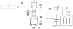
Fig. 3 is a schematic structural view of the suction-crushing system in fig. 2.
In the figure: 1. the device comprises a base, 2, a transverse sliding rail, 3, a transverse screw rod, 4, a transverse sliding table, 5, a transverse servo gear motor, 6, a longitudinal sliding rail, 7, a longitudinal screw rod, 8, a longitudinal sliding table, 9, a longitudinal servo gear motor, 10, a cutter bar mounting rack, 11, a cutter bar, 12, a cutter head, 13, a spindle box, 131, an output shaft, 14, a clamping chuck, 15, a hydraulic station, 16, a workpiece, 17, a bracket, 18, a protective cover shell, 19, a cutting channel, 20, a debris suction system, 201, a dust collector main body, 202, a sedimentation discharging device, 203, a first dust suction hose, 204, a second dust suction hose, 2021, a movable base, 2022, an outer movable roller, 2023, a discharging bin, 2024, a sedimentation cylinder, 2025, an inner rotary air body, 2026, an upper discharging valve, 2027, a lower discharging valve, 2028, a material receiving trolley, 2029 and an inner movable roller.
Detailed Description
The following detailed description of the present invention will be made in conjunction with the accompanying drawings and specific embodiments.
As shown in fig. 1, 2 and 3, the horizontal single-sided boring combined machine tool includes: the base 1 is provided with a transverse slide rail 2 and a transverse screw rod 3 on the base 1, the transverse slide rail 2 is provided with a transverse slide table 4 matched with the transverse slide rail in a sliding manner, the transverse slide table 4 is provided with a transverse screw rod sleeve matched with the transverse screw rod 3, the transverse screw rod 3 is connected with a transverse servo speed-reducing motor 5 arranged on the base 1, the transverse slide table 4 is provided with a longitudinal slide rail 6 and a longitudinal screw rod 7, the longitudinal slide rail 6 is provided with a longitudinal slide table 8 matched with the longitudinal slide rail in a sliding manner, the longitudinal slide table 8 is provided with a longitudinal screw rod sleeve matched with the longitudinal screw rod 7, the longitudinal screw rod 3 is connected with a longitudinal servo speed-reducing motor 9 arranged on the transverse slide table 4, the longitudinal slide table 8 is provided with a cutter bar mounting rack 10, and the cutter bar 11 is arranged on the cutter bar mounting rack 10, one end of the cutter bar 11 is provided with a cutter head 12, a spindle box 13 is arranged on a base 1 at one end of a transverse sliding rail 2, a clamping chuck 14 is arranged on an output shaft 131 of the spindle box 13, a hydraulic station 15 connected with the clamping chuck 14 is arranged on one side of the base 1, a workpiece 16 is clamped on the clamping chuck 14, a bracket 17 matched with the workpiece 16 is arranged on the base 1 at the lower end of the workpiece 16, a protective housing 18 is further arranged on the base 1, a cutting channel 19 is arranged in the cutter bar 11, the other end of the cutter bar 11 is connected with a chip suction system 20, and the chip suction system 20 comprises: the dust collector comprises a dust collector main body 201 and a sedimentation discharge device 202, wherein the dust collector main body 201 is connected with the sedimentation discharge device 202 through a first dust suction hose 203, the sedimentation discharge device 202 is communicated with the discharge cutting channel 19 through a second dust suction hose 204, and the sedimentation discharge device 202 is structurally characterized
The method comprises the following steps: the dust collector comprises a movable base 2021 and an external movable roller 2022 arranged at the lower end of the movable base 2021, wherein the upper end of the movable base 2021 is provided with a discharge bin 2023, the upper end of the discharge bin 2023 is provided with a settling cylinder 2024, the settling cylinder 2024 is internally provided with an internal cyclone 2025, the inner cavity of the settling cylinder 2024 at the upper end of the internal cyclone 2025 is communicated with a first dust suction hose 203, the inner cavity of the settling cylinder 2024 at the lower end of the internal cyclone 2025 is communicated with a second dust suction hose 204, an upper discharge valve 2026 is arranged between the settling cylinder 2024 and the discharge bin 2023, a lower discharge valve 2027 is arranged between the discharge bin 2023 and the movable base 2021, a material receiving trolley 2028 matched with the lower discharge valve 2027 is arranged in the movable base 2021 in a sliding manner, and the lower end of the material receiving trolley 2028 is provided with an internal movable roller 2029.
When the horizontal single-sided boring combined machine tool is used, a workpiece 16 is clamped through a clamping chuck 14, the clamping chuck 14 is automatically clamped through hydraulic control of a hydraulic station 15, after clamping, an output shaft 131 is driven to rotate through a spindle box 13, the output shaft 131 drives the workpiece 16 to rotate through the clamping chuck 14, a transverse servo speed reduction motor 5 and a longitudinal servo speed reduction motor 9 are started, the transverse servo speed reduction motor 5 drives a transverse lead screw 3 to rotate, the transverse lead screw 3 drives a transverse sliding table 4 to move transversely on a transverse sliding rail 2, the longitudinal servo speed reduction motor 9 drives a longitudinal lead screw 7 to rotate, the longitudinal lead screw 7 drives a longitudinal sliding table 8 to move longitudinally on a longitudinal sliding rail 6, the longitudinal sliding table 8 drives a cutter bar 11 to move, the cutter bar 11 drives a cutter head 12 to move, the cutter head 12 performs boring cutting on the workpiece 16 after the cutter head 12 performs tool setting, the boring cutting on the workpiece 16 by half, thereby, the other half of the workpiece 16 is bored, the debris suction system 20 is started simultaneously in the boring process, the dust collector main body 201 in the debris suction system 20 is operated, at the same time, air enters from the gap between the tool bit 12 and the workpiece 16 and is exhausted through the discharge channel 19 in the tool bar 11, the second dust suction hose 204, the sedimentation discharge device 202, the first dust suction hose 203 and the dust collector main body 201 in sequence, and when the air forms an air flow through the gap between the tool bit 12 and the workpiece 16, the air brings the cutting scraps generated during cutting into the discharge channel 19 and enters the sedimentation discharge device 202 through the second dust suction hose 204; in the sedimentation discharge device 202, an upper discharge valve 2026 is opened, a lower discharge valve 2027 is closed, when the airflow passes through an inner cyclone body 2025, an inner cyclone is formed to enable the scraps to be downwards sedimentated and sent into a discharge bin 2023, when the unloading is required, the upper discharge valve 2026 is closed, the lower discharge valve 2027 is opened, the scraps sedimentated in the discharge bin 2023 can directly fall into a material receiving trolley 2028, after the unloading is finished, the upper discharge valve 2026 is opened, the lower discharge valve 2027 is closed, the material receiving trolley is filled with the scraps after the multiple times of unloading, the material receiving trolley 2028 slides out of a movable base 2021 through an inner moving roller 2029, the scraps in the material receiving trolley 2028 can be intensively placed together, and a small part of the scraps sedimentated in the sedimentation discharge device 202 can enter the dust collector main body 201 from a first dust suction hose 203 and are secondarily collected through a collection barrel in the dust collector main body 201.
Above-mentioned horizontal single face bore hole combined machine tool, novel structure sets up in the cutter arbor and arranges and cuts the passageway to cut to the bits through the dust catcher and carry out quick absorption, the bits of broken glass is cut and can be concentrated in inhaling piece system and subside the unloading, arranges to cut effectually, can prevent effectively that the bits of broken glass from splashing and hit and beat operating personnel, eliminates the potential safety hazard, clears up convenient and fast simultaneously, has prolonged clearance period, and labour saving and time saving has reduced workman's intensity of labour.
Claims (1)
1. Horizontal single face bore hole combined machine tool includes: the base (1), be provided with horizontal slide rail (2) and horizontal lead screw (3) on base (1), slide on horizontal slide rail (2) and be provided with rather than horizontal slip table (4) of mutually supporting, be provided with the horizontal lead screw cover of mutually supporting with horizontal lead screw (3) on horizontal slip table (4), horizontal lead screw (3) are connected with horizontal servo gear motor (5) of setting on base (1), be provided with vertical slide rail (6) and vertical lead screw (7) on horizontal slip table (4), slide on vertical slide rail (6) and be provided with rather than longitudinal slip table (8) of mutually supporting, be provided with the vertical lead screw cover of mutually supporting with vertical lead screw (7) on longitudinal slip table (8), vertical lead screw (7) are connected with vertical servo gear motor (9) of setting on horizontal slip table (4), be provided with cutter arbor mounting bracket (10) on vertical slip table (8) be provided with cutter arbor (11) on cutter arbor mounting bracket (10) the one end of cutter arbor (11) is provided with tool bit (12) be provided with headstock (13) on base (1) of transverse slide rail (2) one end be provided with clamping chuck (14) on output shaft (131) of headstock (13) one side of base (1) is provided with hydraulic pressure station (15) that are connected with clamping chuck (14) clamping work piece (16) are gone up to clamping chuck (14) the last bracket (17) that are mutually supported with work piece (16) that is provided with of base (1) of work piece (16) lower extreme still be provided with protective housing (18), its characterized in that: a cutting channel (19) is arranged in the cutter rod (11), the other end of the cutter rod (11) is connected with a debris suction system (20), and the debris suction system (20) structurally comprises: the vacuum cleaner comprises a vacuum cleaner main body (201) and a sedimentation discharge device (202), wherein the vacuum cleaner main body (201) is connected with the sedimentation discharge device (202) through a first dust suction hose (203), the sedimentation discharge device (202) is communicated with a discharge cutting channel (19) through a second dust suction hose (204), and the sedimentation discharge device (202) structurally comprises: the device comprises a movable base (2021) and an external movable roller (2022) arranged at the lower end of the movable base (2021), wherein the upper end of the movable base (2021) is provided with a discharge bin (2023), the upper end of the discharge bin (2023) is provided with a settling cylinder (2024), the settling cylinder (2024) is internally provided with an internal cyclone body (2025), the inner cavity of the settling cylinder (2024) positioned at the upper end of the internal cyclone body (2025) is communicated with a first dust suction hose (203), the inner cavity of the settling cylinder (2024) positioned at the lower end of the internal cyclone body (2025) is communicated with a second dust suction hose (204), an upper discharge valve (2026) is arranged between the settling cylinder (2024) and the discharge bin (2023), a lower discharge valve (2027) is arranged between the discharge bin (2023) and the movable base (2021), and a material receiving trolley (2028) matched with the lower discharge valve (2027) is arranged in the movable base (2021) in a sliding manner, an inner moving roller (2029) is arranged at the lower end of the material receiving trolley (2028).
Priority Applications (1)
| Application Number | Priority Date | Filing Date | Title |
|---|---|---|---|
| CN201920274754.4U CN209954303U (en) | 2019-03-05 | 2019-03-05 | Horizontal single-side boring combined machine tool |
Applications Claiming Priority (1)
| Application Number | Priority Date | Filing Date | Title |
|---|---|---|---|
| CN201920274754.4U CN209954303U (en) | 2019-03-05 | 2019-03-05 | Horizontal single-side boring combined machine tool |
Publications (1)
| Publication Number | Publication Date |
|---|---|
| CN209954303U true CN209954303U (en) | 2020-01-17 |
Family
ID=69238334
Family Applications (1)
| Application Number | Title | Priority Date | Filing Date |
|---|---|---|---|
| CN201920274754.4U Expired - Fee Related CN209954303U (en) | 2019-03-05 | 2019-03-05 | Horizontal single-side boring combined machine tool |
Country Status (1)
| Country | Link |
|---|---|
| CN (1) | CN209954303U (en) |
-
2019
- 2019-03-05 CN CN201920274754.4U patent/CN209954303U/en not_active Expired - Fee Related
Similar Documents
| Publication | Publication Date | Title |
|---|---|---|
| CN106271632B (en) | A kind of system and its production technology for producing tapered sleeve | |
| CN207326449U (en) | A kind of parallel lathe of double five-axle linkage | |
| CN209439851U (en) | A kind of drilling machine chip removing device | |
| CN109894870B (en) | Turning and milling composite numerical control machine tool | |
| CN209954303U (en) | Horizontal single-side boring combined machine tool | |
| CN212330478U (en) | Planer-type milling machine with clear bits device | |
| CN114012485B (en) | Automatic feeding and discharging device of numerical control lathe | |
| CN215698041U (en) | Inner chip removal numerical control chuck cutter-arranging lathe | |
| CN209936481U (en) | Improved chip removal device for machine tool | |
| CN207642342U (en) | A kind of commutator endoporus full-automatic processing machine | |
| CN219292782U (en) | Drilling device for mechanical parts | |
| CN110744088A (en) | Horizontal boring machine for joint drilling | |
| CN220073326U (en) | Double-shaft horizontal boring machine | |
| CN215147271U (en) | Hardware machining drilling machine with cleaning mechanism | |
| CN115256133B (en) | Slender spiral cone grinding machine | |
| CN220782349U (en) | Horizontal plate milling machine | |
| CN218696491U (en) | Boring machine for machining | |
| CN216966380U (en) | A adjustable turret type milling machine for blade production | |
| CN220783194U (en) | Numerical control lathe for double end surfaces of glass mold | |
| CN219648757U (en) | Gang drill machine is used in aluminium alloy plate processing | |
| CN219234706U (en) | Radial drilling machine drilling chip removal device | |
| CN214351177U (en) | High-speed aluminum product cutting machine with self-cleaning function | |
| CN219189502U (en) | Numerical control drilling machine with dust removal function | |
| CN215356345U (en) | Milling cutter processing equipment with piece is collected | |
| CN218696585U (en) | Machine tool with scrap removing function |
Legal Events
| Date | Code | Title | Description |
|---|---|---|---|
| GR01 | Patent grant | ||
| GR01 | Patent grant | ||
| CF01 | Termination of patent right due to non-payment of annual fee | ||
| CF01 | Termination of patent right due to non-payment of annual fee |
Granted publication date: 20200117 Termination date: 20210305 |