CN209944289U - Double-hearth composite combustion corner tube boiler - Google Patents
Double-hearth composite combustion corner tube boiler Download PDFInfo
- Publication number
- CN209944289U CN209944289U CN201920290352.3U CN201920290352U CN209944289U CN 209944289 U CN209944289 U CN 209944289U CN 201920290352 U CN201920290352 U CN 201920290352U CN 209944289 U CN209944289 U CN 209944289U
- Authority
- CN
- China
- Prior art keywords
- water
- wall
- cooled wall
- hearth
- boiler
- Prior art date
- Legal status (The legal status is an assumption and is not a legal conclusion. Google has not performed a legal analysis and makes no representation as to the accuracy of the status listed.)
- Active
Links
Images

Abstract
The utility model discloses a double-hearth composite combustion corner tube boiler, which comprises a boiler body part and a combustion system part. A supporting structure and a double-hearth structure are arranged in the boiler body, and the supporting structure comprises a front side support and a rear side support downcomer which are vertically arranged; the upper end of the front side supporting downcomer is connected with a boiler barrel, the lower end of the front side supporting downcomer is connected with a side water-cooling wall lower header, two ends of the rear side supporting downcomer are respectively connected with a side water-cooling wall upper header and a side water-cooling wall lower header which are horizontally arranged, the boiler barrel is arranged above one side of the boiler body and is connected with a water inlet pipe, and the bottom of the boiler barrel is connected with a downcomer I communicated with the rear side supporting downcomer and a downcomer II connected with a front arch lower header; the double-hearth structure consists of a hearth I and a hearth II; the biomass fuel drying device has the characteristics of high supporting strength, stable structure, energy conservation, environmental protection and the like, and can dry the biomass fuel in a hearth, realize that the fuel can be directly bundled and fully combusted, and reduce the emission of nitrogen oxides.
Description
Technical Field
The utility model relates to a boiler technical field especially can satisfy national boiler atmospheric pollutants emission standard's emission requirement, and it is high to solve the moisture that the living beings were beaten after the bundle, and the calorific value is low, can not the direct combustion, and the burning is insufficient, and the slagging scorification is serious, and nitrogen oxide emission concentration is high, polluted environment's a compound burning corner tube boiler of double furnace.
Background
It is well known that as society's demand for energy increases, fossil fuels, which are the main source of energy, are rapidly decreasing. Therefore, the search for a renewable alternative energy source becomes a focus of general social attention. The biomass energy is important renewable energy and has the characteristics of greenness, low carbon, cleanness, renewability and the like. Accelerating the development and utilization of biomass energy becomes important. However, the existing biomass fuel has the defects of high water content, low heat value, incapability of bundling and direct combustion, burning only after drying moisture, increased use cost, insufficient combustion, high emission concentration of nitrogen oxides, serious slag bonding and low boiler heat efficiency. Therefore, the problem that how to dry the biomass fuel in the furnace so that the biomass fuel can be directly bundled and fully combusted, reduce the emission of nitrogen oxides, solve the problem of slagging and improve the thermal efficiency of the boiler is the urgent need to be solved at present.
Disclosure of Invention
The utility model aims at providing a compound burning angle pipe boiler of double furnace to solve the problem that above-mentioned prior art exists, make biomass fuel can be dry in furnace, and then realize that fuel can directly beat the bundle abundant burning, reduce nitrogen oxide and discharge, thereby improve boiler thermal efficiency.
In order to achieve the above object, the utility model provides a following scheme:
the utility model provides a double-hearth composite combustion angle tube boiler, which comprises a boiler body part and a combustion system part; a supporting structure and a double-hearth structure are arranged in the boiler body, and the supporting structure comprises a front supporting downcomer and a rear supporting downcomer which are vertically arranged; the utility model discloses a boiler, including boiler body, preceding collateral branch supporting downcomer, boiler body, preceding collateral branch supporting downcomer, lower extreme and side water-cooling wall lower header are connected, collection case and side water-cooling wall lower header are connected on the side water-cooling wall that back collateral branch supporting downcomer both ends were equallyd divide and are connected with the level setting respectively, boiler body one side top is provided with the boiler, be connected with the inlet tube on the boiler body, the boiler bottom be connected with the downcomer I of back collateral branch supporting downcomer intercommunication, II bottoms of downcomer are connected with preceding hunch lower header, boiler body internal top be provided with the front and back hunch upper header of front hunch lower header intercommunication, around hunch upper header with the boiler passes through the wet return intercommunication.
Optionally, the double-hearth structure comprises a hearth I and a hearth II, wherein the hearth I is formed by a space surrounded by the upper part of a front arch water-cooled wall, a water-cooled plenum membrane wall, a sealing plate, the upper part of a side water-cooled wall and the upper part of a rear arch water-cooled wall; the hearth II is formed by a space surrounded by the whole front arch water-cooled wall, the rear arch water-cooled wall and the side water-cooled wall; the upper end of the front arch water-cooled wall is connected with the front and rear arch upper header, the lower end of the front arch water-cooled wall is connected with the front arch lower header, the upper end of the side water-cooled wall is connected with the side water-cooled wall upper header, the lower end of the side water-cooled wall is connected with the side water-cooled wall lower header, the upper end of the water-cooled chamber membrane wall is connected with the water-cooled chamber membrane wall upper header, and the lower end of the water-cooled chamber membrane wall is connected with the water-cooled chamber membrane wall lower header; the upper end of the rear arch water-cooled wall is connected with the front and rear arch upper header, the lower end of the rear arch water-cooled wall is connected with the rear arch lower header, a flag type heating surface water-cooled wall is arranged on the outer side of the rear arch water-cooled wall, the top of the flag type heating surface water-cooled wall is connected with an outlet header through the flag type heating surface water-cooled wall upper header, and the bottom of the flag type heating surface water-cooled wall is connected with the flag type heating surface water-cooled wall lower header; a flue gas circulation port is formed above the rear arch water-cooled wall, and a flue gas outlet is formed below the flag type heating surface water-cooled wall.
Optionally, the biomass combustion chamber is designed to be a U-shaped structure, and is formed by a space surrounded by a staggered lean-drawing tube structure bent at the lower part of a front arch water-cooling wall with an inward convex lower part, a staggered lean-drawing tube structure bent at the upper part of a water-cooling plenum membrane wall, and a sealing plate, wherein the lean-drawing tube at the lower part of the front arch water-cooling wall can enable flame at the lower part of the hearth to directly heat the biomass fuel in the biomass combustion chamber to achieve the effect of dry combustion, and further the problems that the biomass fuel cannot be directly bundled and combusted and cannot be fully combusted are solved.
Optionally, the water-cooling plenum is designed into a U-shaped structure and is formed by a space enclosed by a lower water-cooling plenum membrane wall collecting box, an upper water-cooling plenum membrane wall collecting box, a water-cooling plenum membrane wall and a hood, the upper part of the U-shaped water-cooling plenum membrane wall is bent into a staggered rarefied pipe structure, part of the water-cooling plenum membrane wall plays a supporting role, and the hood is fully distributed on the part of the water-cooling plenum membrane wall to play a role in supplying air.
Optionally, the boiler barrel is communicated with a water supply pipe, the top of the water supply pipe is communicated with the flag type heating surface water-cooled wall lower header, the flag type heating surface water-cooled wall lower header is communicated with the flag type heating surface water-cooled wall upper header through the flag type heating surface water-cooled wall, and the flag type heating surface water-cooled wall upper header is communicated with the water outlet header.
Optionally, the sealing plates are arranged in two parallel rows, wherein one sealing plate is opened and the other sealing plate is closed, so that a tight sealing effect is achieved.
Optionally, a throttle ring is arranged on the rear-side supporting downcomer.
Optionally, the bottom of the collector is provided with symmetrically arranged supports under the side walls.
Optionally, the grate part is designed to adopt a chain grate structure, as shown in fig. 1. It is to be noted here that fig. 1, 2 and 3 show the chain grate structure, and fig. 4 shows the reciprocating grate structure. The present technique is also applicable to other grate configurations.
The utility model discloses for prior art gain following technological effect: the design of two furnace and water-cooling plenum makes originally can not directly bundle the biomass fuel of burning and become possible, but also can fully burn, reduces nitrogen oxide and discharges to improve boiler thermal efficiency, simple structure.
Drawings
In order to more clearly illustrate the embodiments of the present invention or the technical solutions in the prior art, the drawings required to be used in the embodiments will be briefly described below, and it is obvious that the drawings in the following description are only some embodiments of the present invention, and for those skilled in the art, other drawings can be obtained according to these drawings without creative efforts.
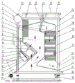
FIG. 1 is a front view of the structure of the embodiment of the dual-hearth composite combustion corner tube boiler of the present invention.
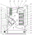
FIG. 2 is a front view of the second structure of the dual-chamber composite combustion corner tube boiler of the present invention.
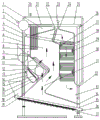
FIG. 3 is a front view of the three structures of the dual-chamber composite combustion corner tube boiler of the present invention.
FIG. 4 is a front view of the four structures of the dual-chamber composite combustion corner tube boiler of the present invention.
In the figure: 1 boiler body, 2 water inlet pipe, 3 boiler barrel, 4 downcomer I, 5 downcomer II, 6 front side support downcomer, 7 hearth I, 8 side water cooling wall, 9 front arch water cooling wall, 10 sealing plate, 11 biomass combustion chamber, 12 water cooling plenum membrane wall upper header, 13 air inlet, 14 water cooling plenum membrane wall lower header, 15 hood, 16 water cooling plenum, 17 water cooling plenum membrane wall, 18 coal hopper, 19 front arch lower header, 20 water supply pipe, 21 upper return pipe, 22 front and rear arch upper header, 23 outlet water header, 24 flag type heating surface water cooling wall upper header, 25 side water cooling wall upper header, 26 rear side support downcomer, 27 rear arch water cooling wall, 28 throttle ring, 29 flag type heating surface, 30 flag type heating surface water cooling wall, 31 hearth II, 32 flag type heating surface water cooling wall lower header, 33 flue gas outlet, 34 rear arch lower header, 35 side water cooling wall lower header, 36 grate, 37 chain.
Detailed Description
The technical solutions in the embodiments of the present invention will be described clearly and completely with reference to the accompanying drawings in the embodiments of the present invention, and it is obvious that the described embodiments are only some embodiments of the present invention, not all embodiments. Based on the embodiments in the present invention, all other embodiments obtained by a person skilled in the art without creative efforts belong to the protection scope of the present invention.
The utility model aims at providing a compound burning angle pipe boiler of double furnace to solve the problem that above-mentioned prior art exists, make biomass fuel can be dry in furnace, and then realize that fuel can directly beat the bundle abundant burning, reduce nitrogen oxide and discharge, thereby improve boiler thermal efficiency.
In order to make the above objects, features and advantages of the present invention more comprehensible, the present invention is described in detail with reference to the accompanying drawings and the detailed description.
Example one
The utility model provides a double-hearth composite combustion corner tube boiler, as shown in figure 1, comprising a boiler body part and a combustion system part. The boiler body part comprises a boiler body 1, four front supporting and descending pipes 6 and rear supporting and descending pipes 26 which are vertically arranged around the boiler body 1 and have the functions of supporting and descending, a throttle ring 28, a boiler barrel 3 arranged on the upper part of the boiler body 1, a water inlet pipe 2 communicated with the boiler barrel 3, a water supply pipe 20, a descending pipe I4, a descending pipe II 5 and an upper water return pipe 21, a side water cooling wall upper header 25, a side water cooling wall 8, a side water cooling wall lower header 35, a hearth I7, a hearth II 31, a front and rear arch upper header 22, a front arch water cooling wall 9, a front arch lower header 19, a sealing plate 10, a biomass combustion chamber 11, a water cooling chamber membrane wall upper header 12, an air inlet 13, a water cooling chamber wall lower header 14, an air cap 15, a water cooling chamber 16, a water cooling chamber membrane wall 17, a rear arch water cooling wall 27, a rear arch lower header 34 and a flag type heating surface wall upper header 24, the device comprises a flag type heating surface water-cooled wall 30, a flag type heating surface 29, a flag type heating surface water-cooled wall lower collection box 32, an outlet water collection box 23, a flue gas outlet 33, a coal hopper 18 and a support 36. The fire grate is arranged at the bottom of the boiler body part and is fixedly connected with the boiler body 1 of the boiler body part.
Specifically, a space surrounded by the upper part of a front arch water-cooling wall 9, a water-cooling air chamber membrane wall 17, a sealing plate 10, the upper part of a side water-cooling wall 8 and the upper part of a rear arch water-cooling wall 27 of a boiler body part forms a hearth I7.
A furnace II 31 is formed by a space surrounded by the front arch water-cooled wall 9, the rear arch water-cooled wall 27, the front arch lower header 19, the front and rear arch upper headers 22 and the side water-cooled walls 8 of the boiler body 1 of the boiler body part.
A biomass combustion chamber 11 is formed by a space surrounded by a bent lower part of a front arch water-cooling wall 9 of a boiler body 1, a bent upper part of a water-cooling air chamber membrane wall 17, a sealing plate 10 and a lower part of a side water-cooling wall 8 of a boiler body part.
A water cooling air chamber 16 is formed by a space enclosed by a water cooling air chamber membrane wall lower header 14, a water cooling air chamber membrane wall upper header 12, a water cooling air chamber membrane wall 17 and a blast cap 15 of a boiler body 1 of a boiler body part.
The boiler water circulation flow is that the boiler backwater flows into the boiler barrel 3 through the water inlet pipe 2, and the boiler effluent flows out through the water outlet header 23. Firstly, the boiler barrel 3, the downcomer II 5 and the front arch lower header 19 are communicated with feed water, and the feed water flows into the front arch upper header 22 and the front arch upper header 21 to return to the boiler barrel 3 after heat exchange of a hearth, so that water circulation of the front arch water-cooled wall 9 is completed; secondly, the boiler barrel 3, the front side supporting downcomer 6 and the side water-cooled wall lower header 35 are communicated with feed water, and the feed water flows into the side water-cooled wall upper header 25 to return to the boiler barrel 3 after heat exchange of a hearth, so that water circulation of the side water-cooled wall 8 is completed; thirdly, a boiler barrel 3, a downcomer I4, a throttling ring 28 and a rear side support downcomer 26, a rear arch lower header 35 is communicated with feed water, the feed water flows into front and rear arch upper headers 22 respectively after heat exchange of a hearth, an upper water return pipe 21 returns to the boiler barrel 3, and water circulation of a rear arch water-cooled wall 27 is completed; and fourthly, the boiler barrel 3 and the water supply pipe 20 are communicated with water supply, the water supply enters the lower collecting box 32 of the flag type heating surface water-cooled wall, enters the flag type heating surface water-cooled wall 30, the flag type heating surface 29 and the upper collecting box 24 of the flag type heating surface water-cooled wall through convection heat exchange, the water circulation of the flag type heating surface water-cooled wall 30 is completed, and water is discharged from the water outlet collecting box 23.
Example two
The present embodiment is a further improvement on the basis of the first embodiment, and includes all the technical features of the first embodiment, as shown in fig. 2, a steam outlet is added on the drum 3, a water outlet header 23 is replaced, a water supply pipe 20 in the body is changed into a gas collecting pipe 20, and the combustion device is a chain grate.
EXAMPLE III
The present embodiment is a further improvement on the basis of the first embodiment, and includes all the technical features of the first embodiment, as shown in fig. 3, the boiler barrel 3 is arranged at the upper right part of the boiler body 1, and the combustion device is a traveling grate.
Example four
The present embodiment is a further improvement on the first embodiment, and includes all the technical features of the first embodiment, as shown in fig. 4, the combustion apparatus is a reciprocating grate.
The utility model discloses a working process and principle do: firstly, biomass particles, crushed materials and coal fall on a chain grate 37 under the action of gravity and are sent into a hearth II 31 to be combusted under the action of mechanical power, the generated heat is absorbed by a front arch water-cooled wall 9, a rear arch water-cooled wall 27 and a side water-cooled wall 8 of the hearth, the generated heat and high-temperature flame are used for drying biomass fuel, directly crushed biomass fuel, granular materials and the like in a biomass combustion chamber 11 through a diluent pipe bent at the lower part of the front arch water-cooled wall 9 and enabling the biomass fuel and the granular materials to be combusted, the generated heat is also absorbed by the front arch water-cooled wall 9, the rear arch water-cooled wall 27 and the side water-cooled wall 8, the cooled flue gas is subjected to flushing heat exchange through a flag-type heating surface 29, the whole heat exchange process is completed, and the flue gas is discharged from an outlet 33, so that the working process of the. Secondly, the boiler water circulation flow is that the boiler backwater flows into the boiler barrel 3 through the water inlet pipe 2, and the boiler effluent flows out through the water outlet header 23. Firstly, the boiler barrel 3, the downcomer II 5 and the front arch lower header 19 are communicated with feed water, and the feed water flows into the front arch upper header 22 and the front arch upper header 21 to return to the boiler barrel 3 after heat exchange of a hearth, so that water circulation of the front arch water-cooled wall 9 is completed; secondly, the boiler barrel 3, the front side supporting downcomer 6 and the side water-cooled wall lower header 35 are communicated with feed water, and the feed water flows into the side water-cooled wall upper header 25 to return to the boiler barrel 3 after heat exchange of a hearth, so that water circulation of the side water-cooled wall 8 is completed; thirdly, a boiler barrel 3, a downcomer I4, a throttling ring 28 and a rear side support downcomer 26, a rear arch lower header 34 is communicated with feed water, the feed water flows into front and rear arch upper headers 22 respectively after heat exchange of a hearth, an upper water return pipe 21 returns to the boiler barrel 3, and water circulation of a rear arch water-cooled wall 27 is completed; and fourthly, the boiler barrel 3 and the water supply pipe 20 are communicated with water supply, the water supply enters the lower collecting box 32 of the flag type heating surface water-cooled wall, enters the flag type heating surface water-cooled wall 30, the flag type heating surface 29 and the upper collecting box 24 of the flag type heating surface water-cooled wall through convection heat exchange, the water circulation of the flag type heating surface water-cooled wall 30 is completed, and water is discharged from the water outlet collecting box 23, so that the whole working process is completed. It is important to point out that this technique double furnace structure and water-cooling wind room structure, the former mainly comprises furnace I7 and furnace II 31, and furnace I7 mainly relies on the high temperature heat and the flame that the fuel burning produced in furnace II 31 to make the biomass fuel of bundling dry the heating in biomass combustion chamber 11 and make its burning, has solved the biomass fuel of direct bundling and can not burn and the insufficient problem of burning. The water-cooling air chamber 16 is designed into a U shape, the upper part of the membrane wall of the U-shaped water-cooling air chamber is bent into a staggered dilution pipe structure, part of the water-cooling air chamber membrane wall 17 plays a supporting role, and the air cap is fully distributed on the part of the water-cooling air chamber membrane wall 17 to play a role in air supply. The technology can be a double-hearth composite combustion angle tube boiler hot water boiler, a steam boiler, a pulverized coal furnace, a fluidized bed boiler and other types of boilers. In addition, the technology can be widely applied to other various corner tube boilers.
The utility model discloses a concrete example is applied to explain the principle and the implementation mode of the utility model, and the explanation of the above example is only used to help understand the method and the core idea of the utility model; meanwhile, for the general technical personnel in the field, according to the idea of the present invention, there are changes in the concrete implementation and the application scope. In summary, the content of the present specification should not be construed as a limitation of the present invention.
Claims (9)
1. The utility model provides a compound burning corner tube boiler of two hearths which characterized in that: comprises a boiler body part and a combustion system part; a supporting structure and a double-hearth structure are arranged in the boiler body, and the supporting structure comprises a front supporting downcomer and a rear supporting downcomer which are vertically arranged; the upper end of the front side supporting downcomer is connected with the boiler barrel, the lower end of the front side supporting downcomer is connected with the lower header of the side water-cooled wall, the two ends of the rear side supporting downcomer are respectively connected with the upper header of the side water-cooled wall and the lower header of the side water-cooled wall, the boiler barrel is arranged above one side of the boiler body, the boiler barrel is connected with a water inlet pipe, the bottom of the boiler barrel is connected with a downcomer I communicated with the rear side supporting downcomer, the bottom of the downcomer II is connected with the lower header of the front arch, the upper portion of the boiler body is provided with the upper header of the front arch and the lower header of the front arch, and the upper header of the front arch and the boiler barrel are communicated through an upper.
2. The double-hearth composite combustion corner tube boiler of claim 1, characterized in that: the double-hearth structure comprises a hearth I and a hearth II, wherein the hearth I is formed by a space enclosed by the upper part of a front arch water-cooled wall, a water-cooled air chamber membrane wall, a sealing plate, the upper part of a side water-cooled wall and the upper part of a rear arch water-cooled wall; the hearth II is formed by a space surrounded by the whole front arch water-cooled wall, the rear arch water-cooled wall and the side water-cooled wall; the upper end of the front arch water-cooled wall is connected with the front and rear arch upper header, the lower end of the front arch water-cooled wall is connected with the front arch lower header, the upper end of the side water-cooled wall is connected with the side water-cooled wall upper header, the lower end of the side water-cooled wall is connected with the side water-cooled wall lower header, the upper end of the water-cooled chamber membrane wall is connected with the water-cooled chamber membrane wall upper header, and the lower end of the water-cooled chamber membrane wall is connected with the water-cooled chamber membrane wall lower header; the upper end of the rear arch water-cooled wall is connected with the front and rear arch upper header, the lower end of the rear arch water-cooled wall is connected with the rear arch lower header, the outer side of the rear arch water-cooled wall is provided with a flag type heating surface water-cooled wall, the top of the flag type heating surface water-cooled wall is connected with an outlet water header through the flag type heating surface water-cooled wall upper header, and the bottom of the flag type heating surface water-cooled wall is connected with the flag type heating surface water-cooled wall lower header; a flue gas circulation port is formed above the rear arch water-cooled wall, and a flue gas outlet is formed below the flag type heating surface water-cooled wall.
3. The dual-hearth composite combustion corner tube boiler of claim 2, characterized in that: the biomass combustion chamber is designed to be of a U-shaped structure and is formed by a space enclosed by a staggered lean-drawing tube structure bent at the lower part of a front arch water-cooling wall with an inward convex lower part, a staggered lean-drawing tube structure bent at the upper part of a water-cooling wind chamber membrane wall and a sealing plate, wherein the lean-drawing tube at the lower part of the front arch can enable flame at the lower part of a hearth to directly heat biomass fuel in the biomass combustion chamber to play a role in dry combustion, and then the problems that the biomass fuel cannot be bundled and combusted and cannot be fully combusted are solved.
4. The dual-hearth composite combustion corner tube boiler of claim 3, characterized in that: the water-cooling air chamber is designed into a U-shaped structure and is formed by a space enclosed by a lower water-cooling air chamber membrane wall collecting box, an upper water-cooling air chamber membrane wall collecting box, a water-cooling air chamber membrane wall and an air cap, the upper part of the U-shaped water-cooling air chamber membrane wall is bent into a staggered dilution pipe structure, part of the water-cooling air chamber membrane wall plays a supporting role, and the air cap is fully distributed on the part of the water-cooling air chamber membrane wall to play an air supply role.
5. The dual-hearth composite combustion corner tube boiler of claim 2, characterized in that: the boiler barrel is communicated with a water supply pipe, the top of the water supply pipe is communicated with a lower collecting box of the flag type heating surface water-cooled wall, the lower collecting box of the flag type heating surface water-cooled wall is communicated with an upper collecting box of the flag type heating surface water-cooled wall through the flag type heating surface water-cooled wall, and the upper collecting box of the flag type heating surface water-cooled wall is communicated with an outlet collecting box.
6. The dual-hearth composite combustion corner tube boiler of claim 3, characterized in that: the sealing plates are arranged in parallel in two rows, wherein one sealing plate is opened and the other sealing plate is closed, so that the sealing effect is realized.
7. The double-hearth composite combustion corner tube boiler of claim 1, characterized in that: the rear side support downcomer is provided with a throttling ring.
8. The double-hearth composite combustion corner tube boiler of claim 1, characterized in that: the bottom of the collector is provided with symmetrically arranged supports under the side wall.
9. The double-hearth composite combustion corner tube boiler of claim 1, characterized in that: the fire grate part adopts a chain fire grate structure.
Priority Applications (1)
| Application Number | Priority Date | Filing Date | Title |
|---|---|---|---|
| CN201920290352.3U CN209944289U (en) | 2019-03-08 | 2019-03-08 | Double-hearth composite combustion corner tube boiler |
Applications Claiming Priority (1)
| Application Number | Priority Date | Filing Date | Title |
|---|---|---|---|
| CN201920290352.3U CN209944289U (en) | 2019-03-08 | 2019-03-08 | Double-hearth composite combustion corner tube boiler |
Publications (1)
| Publication Number | Publication Date |
|---|---|
| CN209944289U true CN209944289U (en) | 2020-01-14 |
Family
ID=69123208
Family Applications (1)
| Application Number | Title | Priority Date | Filing Date |
|---|---|---|---|
| CN201920290352.3U Active CN209944289U (en) | 2019-03-08 | 2019-03-08 | Double-hearth composite combustion corner tube boiler |
Country Status (1)
| Country | Link |
|---|---|
| CN (1) | CN209944289U (en) |
Cited By (1)
| Publication number | Priority date | Publication date | Assignee | Title |
|---|---|---|---|---|
| CN109737372A (en) * | 2019-03-08 | 2019-05-10 | 哈尔滨四方锅炉有限公司 | A kind of twin furnace compound combustion corner tube boiler |
-
2019
- 2019-03-08 CN CN201920290352.3U patent/CN209944289U/en active Active
Cited By (1)
| Publication number | Priority date | Publication date | Assignee | Title |
|---|---|---|---|---|
| CN109737372A (en) * | 2019-03-08 | 2019-05-10 | 哈尔滨四方锅炉有限公司 | A kind of twin furnace compound combustion corner tube boiler |
Similar Documents
| Publication | Publication Date | Title |
|---|---|---|
| CN106594698A (en) | Biomass direct-fired boiler | |
| CN203571721U (en) | Combustion heating system taking biomass as fuel | |
| CN108758651A (en) | A kind of circulating fluidized bed boiler suitable for waste incineration | |
| CN216131907U (en) | Biomass fuel burning corner tube type steam boiler | |
| CN206398704U (en) | A kind of multi fuel multifuel combustion fluidized-bed combustion boiler | |
| CN103256607A (en) | Compound-type waste incineration boiler | |
| CN209944289U (en) | Double-hearth composite combustion corner tube boiler | |
| CN101354129A (en) | Biomass and fire coal composite fuel boiler | |
| CN209944290U (en) | Double-hearth composite combustion settling chamber corner tube boiler | |
| CN211233362U (en) | Double-drum double-hearth composite combustion settling chamber corner tube boiler | |
| CN209944291U (en) | Single-drum double-hearth composite combustion settling chamber corner tube boiler | |
| CN211233361U (en) | Layer combustion type composite combustion double-hearth | |
| CN209944737U (en) | Composite combustion fluidized bed type double-hearth | |
| CN201066195Y (en) | Horizontal type reverse-combusting coal-firing boiler | |
| CN203549758U (en) | Carbon calciner waste heat boiler | |
| CN203384986U (en) | Composite garbage incineration boiler | |
| CN214620090U (en) | Biomass-fired corner-tube type organic heat carrier boiler | |
| CN209541168U (en) | Coal dust organic heat carrier furnace in bulk | |
| CN202546779U (en) | Pi-shaped garbage incineration boiler | |
| CN109737371A (en) | A kind of twin furnace compound combustion expansion chamber corner tube boiler | |
| CN111765475A (en) | Circulating fluidized bed waste incineration boiler based on fire grate and working method thereof | |
| CN201954528U (en) | Secondary combustion and discharge device for slag and smoke dust of biomass direct combustion generating boiler | |
| CN206398686U (en) | Biomass direct-combustion boiler | |
| CN205535709U (en) | Flue waste heat utilization system | |
| CN104359100A (en) | Biomass combustion power generation boiler |
Legal Events
| Date | Code | Title | Description |
|---|---|---|---|
| GR01 | Patent grant | ||
| GR01 | Patent grant |