CN209942277U - Supporting device for mounting aluminum alloy template - Google Patents
Supporting device for mounting aluminum alloy template Download PDFInfo
- Publication number
- CN209942277U CN209942277U CN201920536623.9U CN201920536623U CN209942277U CN 209942277 U CN209942277 U CN 209942277U CN 201920536623 U CN201920536623 U CN 201920536623U CN 209942277 U CN209942277 U CN 209942277U
- Authority
- CN
- China
- Prior art keywords
- support
- seat
- lifting
- supporting
- sub
- Prior art date
- Legal status (The legal status is an assumption and is not a legal conclusion. Google has not performed a legal analysis and makes no representation as to the accuracy of the status listed.)
- Active
Links
Images


Landscapes
- Forklifts And Lifting Vehicles (AREA)
Abstract
The utility model belongs to the technical field of aluminum alloy template support, a support device for aluminum alloy template installation is disclosed, which comprises a support seat, wherein a lifting seat is arranged on the support seat, a plurality of vertical telescopic driving mechanisms are arranged at the top of the lifting seat, and the lifting seat is connected with a support plate assembly through the telescopic driving mechanisms; the supporting plate assembly comprises a plurality of supporting sub-plates; the bottom of the support sub-plate is connected with a telescopic end of a telescopic driving mechanism through a movable joint; the periphery of the support sub-board is connected with the adjacent support sub-boards through movable connecting pieces. The utility model provides a current support equipment can not carry out the problem that effectively supports to the template at step position, can adapt to different inclination's template and support to better supporting aluminum alloy template, easy dismounting is practical moreover, be convenient for remove.
Description
Technical Field
The utility model belongs to the technical field of the building templates supports, concretely relates to a strutting arrangement for be used for aluminum alloy template installation.
Background
The aluminum alloy template has the advantages of light weight, high strength, good stability, repeated turnover use, good concrete forming effect and the like, is gradually replacing wood molds and large steel molds to become a preferred template form in the construction process at present, and has wider and wider application prospects in high-rise and super high-rise construction projects.
However, most of the traditional formwork supporting devices used in engineering construction processes such as buildings, bridges and the like are tripod supports or wooden frames, the traditional formwork supporting devices can play a great role in horizontally supporting the formwork, in the construction process, supporting devices capable of inclining angles such as stairs or ramps are needed in many cases, and the traditional formwork supporting devices are mostly horizontally supported and cannot adapt to different slopes; moreover, the existing supporting equipment can not effectively support the template with the stepped engineering part, so that the use is inconvenient, and the used equipment is more, complex in disassembly and assembly and inconvenient to use.
SUMMERY OF THE UTILITY MODEL
For the above-mentioned technical problem who solves prior art existence, the utility model aims to provide a strutting arrangement for aluminum alloy template installation.
The utility model discloses the technical scheme who adopts does:
a supporting device for mounting an aluminum alloy template comprises a supporting seat, wherein a lifting seat is arranged on the supporting seat, a plurality of vertical telescopic driving mechanisms are arranged at the top of the lifting seat, and the lifting seat is connected with a supporting plate assembly through the telescopic driving mechanisms; the supporting plate assembly comprises a plurality of supporting sub-plates; the bottom of the support sub-plate is connected with a telescopic end of a telescopic driving mechanism through a movable joint; the periphery of the support sub-board is connected with the adjacent support sub-boards through movable connecting pieces.
Furthermore, for better explanation of the present invention, the movable connecting member includes a first fixed shaft and a connecting band; the first fixing shaft is arranged on the side end face of the support daughter board, one end of the connecting belt is connected to the first fixing shaft, and the other end of the connecting belt is connected to the first fixing shaft on the same side of the adjacent support daughter board.
Furthermore, for better explanation of the present invention, the movable connecting member includes a second fixed shaft, a movable sleeve and a fork-shaped movable frame; the second fixed shaft is arranged on the side end face of the support sub-plate, the two ends of the second fixed shaft are connected with the moving sleeves in a sliding mode, the two moving sleeves on the second fixed shaft are hinged to the connecting end of the same side of the fork-shaped movable frame respectively, and the connecting end of the other same side of the fork-shaped movable frame is hinged to the moving sleeves on the second fixed shaft of the adjacent support sub-plate respectively.
Furthermore, for better explanation of the present invention, the telescopic driving mechanism includes a guiding bracket, a telescopic driving component and a lifting rod; the guide bracket is connected to the top of the lifting seat through a bolt, and a guide hole corresponding to the telescopic driving part is arranged on the top of the guide bracket in a vertically through manner; the top of lift seat is provided with a plurality of mounting grooves that are used for installing flexible driver part, flexible driver part's output fixed connection lifter, the one end that the lift seat was kept away from to the lifter slides and wears to establish the guiding hole to be connected with the support daughter board through the swing joint.
Further, for the better the utility model discloses explain, flexible drive unit is flexible motor, cylinder or pneumatic cylinder.
Furthermore, for better explaining the utility model, the supporting seat is of a groove structure, the lifting seat can be connected in the supporting seat in a vertical sliding way, and a lifting driving mechanism is arranged between the bottom of the lifting seat and the bottom of the inner side of the supporting seat; the lifting driving mechanism comprises a fork-shaped lifting frame and a hydraulic driving cylinder; the bottom end of the lifting seat is provided with an upper waist-shaped sliding hole in a through manner, the bottom of the inner side of the supporting seat is provided with a lower waist-shaped sliding hole corresponding to the upper waist-shaped sliding hole, sliding shafts are arranged in the upper waist-shaped sliding hole and the lower waist-shaped sliding hole, and the fork-shaped lifting frame is movably connected between the lifting seat and the supporting seat through the sliding shafts; and a hydraulic driving cylinder is arranged on the inner side of the supporting seat, and the driving end of the hydraulic driving cylinder is connected with the sliding shaft.
Furthermore, in order to better explain the utility model, a support rod is arranged at the bottom of the support seat, and a movable wheel is arranged at the bottom end of the support rod; the supporting rod is sleeved with a fixed sleeve, a connecting rod is perpendicularly arranged on the outer side of the fixed sleeve, the connecting rod is connected with a positioning cylinder parallel to the fixed sleeve, and a positioning pin is arranged in the positioning cylinder.
Furthermore, for better illustration of the present invention, the support sub-boards of the support board assembly are arranged in a 9 × 9 format.
The utility model has the advantages that:
(1) the utility model discloses a set up supporting seat, lift seat, flexible actuating mechanism and backup pad subassembly, the support daughter board of backup pad subassembly can better relative lift through the swing joint spare, has realized that the backup pad subassembly supports the function that the step-shaped aluminum alloy template; the support sub-board can be inclined at different angles through the movable joint, so that the functions of attaching and supporting templates with different inclinations are realized; and more convenient and practical, the range of application is wider, simple to operate.
(2) The utility model discloses an adopt the swing joint spare of connecting band structure, can enough make each support daughter board connect into a mobilizable whole, can not influence each other when relative activity for adjacent support daughter board again to carry out better support to the template.
(3) The utility model discloses an adopt the swing joint spare of Y-shaped adjustable shelf structure, when can satisfying the relative activity of adjacent support daughter board, can carry out better support and keep out the template of slope for the supporting role is better.
(4) The utility model has the advantages that by arranging the guide bracket, the telescopic driving part and the lifting rod, the support sub-plate can be driven by the corresponding telescopic driving part to correspondingly support different parts of the template, so that the step-shaped template and the templates with different gradients can be supported; the lifting rod can perform a good guiding function through the guide bracket, and the structure is more stable; the guide support is connected with the lifting seat through bolts, so that the guide support is more convenient to disassemble and maintain.
(5) The utility model discloses a set up the supporting seat of cell type structure and the lift actuating mechanism between lift seat and the supporting seat, the drive end of hydraulic drive jar can make the horizontal removal of slide bar be connected with the Y-shaped crane, and then can drive the Y-shaped crane and carry out the ascending concertina movement of longitudinal direction to the lift operation of direction about driving the lift seat and carrying out in the supporting seat realizes the utility model discloses to the support of co-altitude template, it is more convenient.
(6) The utility model can move better by arranging the support rods and the movable wheels, thereby being more convenient for use in the process of installing the template; through setting up fixed cover, connecting rod, a location section of thick bamboo and locating pin, be convenient for the utility model discloses can carry out better location when removing preset position, prevent to remove, provide better bearing condition.
Drawings
FIG. 1 is a schematic structural view of the movable connecting member of the present invention as a connecting band;
fig. 2 is a top view structural diagram of the support plate assembly of the present invention connected by the connecting band;
fig. 3 is a schematic structural view of the connection belt of the present invention connected to the adjacent support daughter boards;
fig. 4 is a schematic structural view of a supporting state of the present invention;
fig. 5 is a schematic structural view of another supporting state of the present invention;
FIG. 6 is a schematic structural view of the movable connecting member of the present invention being a fork-shaped movable frame;
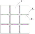
fig. 7 is a top view structural diagram of the supporting plate assembly of the present invention connected by the fork-shaped movable frame;
fig. 8 is a schematic structural view of the connection between the fork-shaped movable frame and the adjacent support sub-plate of the present invention;
fig. 9 is a schematic structural view of another middle supporting state of the present invention when the movable connecting member is a fork-shaped movable frame.
In the figure: 1-a support seat; 2-a lifting seat; 3-a guide bracket; 4-a telescopic drive member; 5-a lifting rod; 6-supporting the daughter board; 7-a movable joint; 8-a first fixed shaft; 9-connecting the belt; a 10-forked lifting frame; 11-programmable PLC controller; 12-a slide shaft; 13-lower waist-shaped sliding hole; 14-a support bar; 15-fixing the sleeve; 16-a moving wheel; 17-a positioning cylinder; 18-a locating pin; 19-a second fixed shaft; 20-fork shaped movable frame; 21-moving the sleeve; 22-hydraulic drive cylinder.
Detailed Description
The present invention will be further described with reference to the accompanying drawings and specific embodiments.
With reference to fig. 1-9, a supporting device for mounting an aluminum alloy template comprises a supporting seat 1, wherein a lifting seat 2 is arranged on the supporting seat 1, a plurality of vertical telescopic driving mechanisms are arranged at the top of the lifting seat 2, and the lifting seat 2 is connected with a supporting plate assembly through the telescopic driving mechanisms; the supporting plate assembly comprises a plurality of supporting sub-plates 6; the bottom of the support sub-plate 6 is connected with a telescopic end of a telescopic driving mechanism through a movable joint 7; the periphery of the support sub-board 6 is connected with the adjacent support sub-boards 6 through movable connecting pieces.
The supporting seat 1 is used for supporting the device, the lifting seat 2 arranged on the supporting seat 1 is preferably arranged to be capable of lifting up and down, and the lifting driving mode can be driven by a hydraulic cylinder or a lifting driving mechanism with a scissor structure. The plurality of telescopic driving mechanisms on the lifting seat 2 are preferably arranged in a matrix, and may be transversely arranged side by side without limitation. The support daughter board 6 is corresponding to one telescopic driving mechanism, the telescopic driving mechanism drives the support daughter board 6 to ascend and descend and is attached to the template, the support daughter board 6 is connected with the telescopic end of the telescopic driving mechanism through the movable connector 7, and therefore the support daughter board 6 can be supported by templates with different gradients and different inclination directions. In particular, the movable joint 7 is a universal joint. The supporting plate component mainly comprises a plurality of supporting sub-plates 6 and a movable connecting piece, the movable connecting piece is used for enabling the adjacent supporting sub-plates 6 to move relatively under the condition of connection, the supporting sub-plates 6 are connected into a whole, the stepped template position and templates with different gradients are supported, the structure is simple, and the supporting plate component is practical and convenient and is convenient to support.
Further, as a preference of one of the embodiments, as shown in fig. 1 to 5, the movable connecting member includes a first fixed shaft 8 and a connecting band 9; the first fixing shaft 8 is arranged on the side end face of the support daughter board 6, one end of the connecting belt 9 is connected to the first fixing shaft 8, and the other end of the connecting belt 9 is connected to the first fixing shaft 8 on the same side of the adjacent support daughter board 6.
Fig. 1 to 5 are schematic structural views of the movable connecting member when the connecting strap 9 is used, the connecting strap 9 is disposed on the supporting sub-plate 6 through the first fixing shaft 8 fixedly disposed on the side section of the supporting sub-plate 6, and the adjacent supporting sub-plates 6 are connected through the connecting strap 9, so that the ascending or descending of part of the supporting sub-plates 6 can support the stepped formwork, and a good movable space can be provided without mutual interference. By adopting the connecting band 9 as a movable connecting piece, the replacement is convenient, the cost is low, and the structure is simple and practical.
Further, as a preference of one of the embodiments, as shown in fig. 6 to 9, the movable connecting member includes a second fixed shaft 19, a moving sleeve 21, and a fork-shaped movable frame 20; the second fixed shaft 19 is arranged on the side end surface of the support sub-plate 6, and two ends of the second fixed shaft 19 are slidably connected with moving sleeves 21, the two moving sleeves 21 on the second fixed shaft 19 are respectively hinged with the connecting end of the same side of the fork-shaped movable frame 20, and the connecting end of the other same side of the fork-shaped movable frame 20 is respectively hinged with the moving sleeve 21 on the second fixed shaft 19 of the adjacent support sub-plate 6.
Fig. 6-9 are schematic structural views of the movable connecting part being a fork-shaped movable frame 20, and the fork-shaped movable frame 20 is a scissor-fork structure and comprises two movable rods with middle parts rotatably connected. The movable sleeve 21 on the second fixed shaft 19 supporting the side end face of the daughter board 6 is movable in the axial direction thereof and rotatable around the circumferential direction thereof, and is used for coupling with the fork-shaped movable frame 20. The connecting end of the same side of the fork-shaped movable frame 20 is hinged with the moving sleeve 21 on the second fixed shaft 19 of the adjacent support sub-plate 6, and the connecting end of the same side of the fork-shaped movable frame 20 is hinged with the moving sleeve 21 on the other adjacent support sub-plate 6, so that when the two adjacent support sub-plates 6 move relatively in the vertical direction, the fork-shaped movable frame 20 can stretch and retract through the relative movement of the moving sleeve 21 on the second fixed shaft 19, and further, a stretching effect is provided for the relative movement of the adjacent support sub-plates 6. By adopting the movable connecting piece of the fork-shaped movable frame 20, the vertical and inclined template parts can be attached and supported, so that the template is more convenient to install. As shown in fig. 9, the stepped template portion can be correspondingly supported.
Further, as shown in fig. 1, preferably, the telescopic driving mechanism includes a guide bracket 3, a telescopic driving member 4 and a lifting rod 5, the guide bracket 3 is connected to the top of the lifting seat 2 by a bolt, and a guide hole corresponding to the telescopic driving member 4 is vertically arranged on the top of the guide bracket 3 in a penetrating manner; the top of seat 2 goes up and down is provided with a plurality of mounting grooves that are used for installing flexible driver part 4, the output fixed connection lifter 5 of flexible driver part 4, the one end that lifter 5 kept away from seat 2 slides and wears to establish the guiding hole to be connected with support daughter board 6 through swing joint 7.
The preferred supporting structure of guide bracket 3, including the guiding disc seat at top and integrative the peripheral supporting legs in guiding disc seat bottom that sets up, the supporting legs is connected through the bolt with lift seat 2, the dismouting and the maintenance of being convenient for like this. An inner cavity is formed between the inner side of the guide bracket 3 and the lifting seat 2 and is used for providing space for the extension and retraction of the extension end of the extension and retraction driving part 4. The lifting rod 5 is connected in a guide hole of the guide support 3 in a sliding manner and can be driven by the telescopic driving part 4 to lift up and down, so that the support sub-plate 6 can be lifted to a height corresponding to the template degree to support. The mounting groove is used for mounting the telescopic driving part 4.
Further, as a preferred embodiment, the telescopic driving member 4 is a telescopic motor, a pneumatic cylinder or a hydraulic cylinder.
The telescopic driving means 4 may be any one of a telescopic motor, an air cylinder, and a hydraulic cylinder, but is preferably driven by a hydraulic cylinder, and is not limited thereto. When the motor stretches out and draws back, flexible motor installs in the mounting groove, and the telescopic shaft of flexible motor stretches out the mounting groove outward with lifter 5 fixed connection. When the cylinder is adopted, the cylinder is arranged in the mounting groove, and the cylinder rod extends out of the mounting groove and is fixedly connected with the lifting rod 5. The hydraulic cylinder and the air cylinder are mounted in the same way.
Further, as a preferable embodiment, the supporting seat 1 is of a groove-shaped structure, the lifting seat 2 is connected in the supporting seat 1 in a vertically sliding manner, and a lifting driving mechanism is arranged between the bottom of the lifting seat 2 and the bottom of the inner side of the supporting seat 1; the lifting driving mechanism comprises a fork-shaped lifting frame 10 and a hydraulic driving cylinder 22, an upper waist-shaped sliding hole is formed in the bottom end of the lifting seat 2 in a penetrating mode, a lower waist-shaped sliding hole 13 corresponding to the upper waist-shaped sliding hole is formed in the bottom of the inner side of the supporting seat 1, sliding shafts 12 are arranged in the upper waist-shaped sliding hole and the lower waist-shaped sliding hole 13, and the fork-shaped lifting frame 10 is movably connected between the lifting seat 2 and the supporting seat 1 through the sliding shafts 12; the inner side of the supporting seat 1 is provided with a hydraulic driving cylinder 22, and the driving end of the hydraulic driving cylinder 22 is connected with the sliding shaft 12.
The lifting seat 2 is arranged in the supporting seat 1 through a connecting structure which can slide up and down, the connecting structure can be a sliding groove sliding block type connecting structure, and can also be a sliding connecting structure of a pulley and a sliding rail, of course, the sliding connecting structure is provided with a limiting structure which is used for preventing the lifting seat 2 from rising to be separated from the supporting seat 1, and the limiting structure adopts the prior art. Lifting drive mechanism is used for driving lift seat 2 to reciprocate in supporting seat 1, Y-shaped crane 10 is the same with Y-shaped adjustable shelf 20, and set up two and set up respectively in lift seat 2's both sides, the last link on Y-shaped crane 10's right side with and lower link respectively with lift seat 2, supporting seat 1 is articulated, Y-shaped crane 10 left last link and lower link are articulated with slide-shaft 12 respectively, under hydraulic drive jar 22's flexible drive like this, can make slide-shaft 12 carry out round trip movement, realize the flexible of last phase direction of Y-shaped crane 10, thereby drive the reciprocating of lift seat 2, can make this device can support the template of greater height like this, moreover, the steam generator is simple in structure, and is practical.
Further, as a preferred embodiment, a support rod 14 is arranged at the bottom of the support seat 1, and a moving wheel 16 is arranged at the bottom end of the support rod 14; the utility model discloses a supporting rod, including bracing piece 14, fixed cover 15 is overlapped on the bracing piece 14, the outside of fixed cover 15 is provided with the connecting rod perpendicularly, the connecting rod is connected with a location section of thick bamboo 17 parallel with fixed cover 15, be provided with locating pin 18 in the location section of thick bamboo 17.
By arranging the support rod 14 and the moving wheel 16 under the support seat 1, the movement can be better performed, and the moving wheel 16 can be an existing universal wheel with a limiting function. The fixed cover of fixed cover 15 is established on bracing piece 14, and a location section of thick bamboo 17 is parallel with fixed cover 15, and locating pin 18 in a location section of thick bamboo 17 is used for being connected and realizes the rigidity of this device with ground or at concrete plane trompil, supports for the template and adjusts that provides stable support.
Further, as a preference of one embodiment, the supporting sub-boards 6 of the supporting board assembly are arranged in a 9 × 9 format.
The supporting plate assembly arranged in the 9 x 9 specification is adopted, so that the aluminum alloy template can be reasonably and conveniently supported.
It should be noted that the present invention preferably controls the telescopic driving part 4 and the hydraulic driving cylinder 22 through the programmable PLC controller 11, and controls the supporting force of the formwork support by cooperating with the pressure sensor arranged between the movable joint 7 and the lifting rod 5, and when the telescopic driving part 4 applies pressure to the formwork through the supporting sub-plate 6 to reach a set value, the programmable PLC controller 11 controls the telescopic driving part 4 to stop driving; the programmable PLC controller 11 respectively controls the telescopic driving components 4, and certainly, the hydraulic driving cylinder 22 is also controlled, so that the lifting seat 2 can be lifted; the utility model discloses a power supply unit, control circuit and control principle all belong to prior art earlier, and do not belong to the utility model discloses an improvement point, the event is no longer repeated.
The present invention is not limited to the above-mentioned optional embodiments, and any other products in various forms can be obtained by anyone under the teaching of the present invention, and any changes in the shape or structure thereof, all the technical solutions falling within the scope of the present invention, are within the protection scope of the present invention.
Claims (8)
1. The utility model provides a strutting arrangement for be used for aluminum alloy template installation which characterized in that: the lifting device comprises a supporting seat (1), wherein a lifting seat (2) is arranged on the supporting seat (1), a plurality of vertical telescopic driving mechanisms are arranged at the top of the lifting seat (2), and the lifting seat (2) is connected with a supporting plate assembly through the telescopic driving mechanisms; the supporting plate component comprises a plurality of supporting sub-plates (6); the bottom of the support sub-plate (6) is connected with a telescopic end of a telescopic driving mechanism through a movable joint (7); the periphery of the support sub-board (6) is connected with the adjacent support sub-board (6) through a movable connecting piece.
2. A support arrangement for an aluminium alloy formwork installation according to claim 1, wherein: the movable connecting piece comprises a first fixed shaft (8) and a connecting belt (9); the first fixing shaft (8) is arranged on the side end face of the support sub-board (6), one end of the connecting belt (9) is connected to the first fixing shaft (8), and the other end of the connecting belt (9) is connected to the first fixing shaft (8) on the same side of the adjacent support sub-board (6).
3. A support arrangement for an aluminium alloy formwork installation according to claim 1, wherein: the movable connecting piece comprises a second fixed shaft (19), a movable sleeve (21) and a fork-shaped movable frame (20); the second fixing shaft (19) is arranged on the side end face of the support sub-plate (6), the two ends of the second fixing shaft (19) are connected with moving sleeves (21) in a sliding mode, the two moving sleeves (21) on the second fixing shaft (19) are hinged to the connecting end of the same side of the fork-shaped moving frame (20), and the connecting end of the other side of the fork-shaped moving frame (20) is hinged to the moving sleeve (21) on the second fixing shaft (19) of the adjacent support sub-plate (6).
4. A support arrangement for an aluminium alloy formwork installation according to any one of claims 1 to 3, wherein: the telescopic driving mechanism comprises a guide bracket (3), a telescopic driving part (4) and a lifting rod (5); the guide support (3) is connected to the top of the lifting seat (2) through a bolt, and a guide hole corresponding to the telescopic driving part (4) is formed in the top of the guide support (3) in a vertically through mode; the top of lift seat (2) is provided with a plurality of mounting grooves that are used for installing flexible driver part (4), output fixed connection lifter (5) of flexible driver part (4), the guiding hole is worn to establish in the one end slip that lift seat (2) were kept away from in lifter (5) to be connected with support daughter board (6) through activity joint (7).
5. A support arrangement for an aluminium alloy formwork installation according to claim 4, wherein: the telescopic driving part (4) is a telescopic motor, an air cylinder or a hydraulic cylinder.
6. A support arrangement for an aluminium alloy formwork installation according to claim 1, wherein: the supporting seat (1) is of a groove-shaped structure, the lifting seat (2) can be connected in the supporting seat (1) in a vertically sliding mode, and a lifting driving mechanism is arranged between the bottom of the lifting seat (2) and the bottom of the inner side of the supporting seat (1); the lifting driving mechanism comprises a fork-shaped lifting frame (10) and a hydraulic driving cylinder (22); an upper waist-shaped sliding hole is formed in the bottom end of the lifting seat (2) in a penetrating mode, a lower waist-shaped sliding hole (13) corresponding to the upper waist-shaped sliding hole is formed in the bottom of the inner side of the supporting seat (1), sliding shafts (12) are arranged in the upper waist-shaped sliding hole and the lower waist-shaped sliding hole (13), and the fork-shaped lifting frame (10) is movably connected between the lifting seat (2) and the supporting seat (1) through the sliding shafts (12); the inner side of the supporting seat (1) is provided with a hydraulic driving cylinder (22), and the driving end of the hydraulic driving cylinder (22) is connected with the sliding shaft (12).
7. A support arrangement for an aluminium alloy formwork installation according to claim 1, wherein: a support rod (14) is arranged at the bottom of the support seat (1), and a moving wheel (16) is arranged at the bottom end of the support rod (14); the utility model discloses a fixed cover of solar cell, including bracing piece (14), the cover is equipped with fixed cover (15) on bracing piece (14), the outside of fixed cover (15) is provided with the connecting rod perpendicularly, the connecting rod is connected with a location section of thick bamboo (17) parallel with fixed cover (15), be provided with locating pin (18) in a location section of thick bamboo (17).
8. A support arrangement for an aluminium alloy formwork installation according to claim 1, wherein: the support sub-plates (6) of the support plate assembly are arranged in a 9 x 9 specification.
Priority Applications (1)
| Application Number | Priority Date | Filing Date | Title |
|---|---|---|---|
| CN201920536623.9U CN209942277U (en) | 2019-04-19 | 2019-04-19 | Supporting device for mounting aluminum alloy template |
Applications Claiming Priority (1)
| Application Number | Priority Date | Filing Date | Title |
|---|---|---|---|
| CN201920536623.9U CN209942277U (en) | 2019-04-19 | 2019-04-19 | Supporting device for mounting aluminum alloy template |
Publications (1)
| Publication Number | Publication Date |
|---|---|
| CN209942277U true CN209942277U (en) | 2020-01-14 |
Family
ID=69128791
Family Applications (1)
| Application Number | Title | Priority Date | Filing Date |
|---|---|---|---|
| CN201920536623.9U Active CN209942277U (en) | 2019-04-19 | 2019-04-19 | Supporting device for mounting aluminum alloy template |
Country Status (1)
| Country | Link |
|---|---|
| CN (1) | CN209942277U (en) |
Cited By (2)
| Publication number | Priority date | Publication date | Assignee | Title |
|---|---|---|---|---|
| CN111576597A (en) * | 2020-06-04 | 2020-08-25 | 福建岚泰锦盛建设发展有限公司 | Municipal works drainage open channel construction fixing device |
| CN114293816A (en) * | 2022-02-10 | 2022-04-08 | 杨文超 | Fixing support for building engineering template |
-
2019
- 2019-04-19 CN CN201920536623.9U patent/CN209942277U/en active Active
Cited By (2)
| Publication number | Priority date | Publication date | Assignee | Title |
|---|---|---|---|---|
| CN111576597A (en) * | 2020-06-04 | 2020-08-25 | 福建岚泰锦盛建设发展有限公司 | Municipal works drainage open channel construction fixing device |
| CN114293816A (en) * | 2022-02-10 | 2022-04-08 | 杨文超 | Fixing support for building engineering template |
Similar Documents
| Publication | Publication Date | Title |
|---|---|---|
| CN209942277U (en) | Supporting device for mounting aluminum alloy template | |
| CN109132875A (en) | Rubber-tyred tunnel tracklaying crane and construction method | |
| CN105345420B (en) | A kind of undercarriage attaching/detaching apparatus | |
| CN102996062A (en) | Maintenance lifting platform and application method thereof | |
| CN109694024A (en) | A kind of self-propelled lifting hoisting platform device | |
| CN105537898A (en) | Tool for assembling reinforcing steel mesh cages | |
| CN208200190U (en) | Lifting equipment is used in power equipment installation | |
| CN202704979U (en) | Operation platform lifter for assembling and maintaining large devices | |
| CN202594653U (en) | Lifting platform | |
| CN205935678U (en) | Assembled stair mold dismouting device | |
| CN205968906U (en) | Engine asseumbly lifts turning device | |
| CN207108299U (en) | A kind of loop wheel machine | |
| CN212356446U (en) | Tower type multi-mast aerial work platform | |
| CN211169589U (en) | High-stability beam lifting machine | |
| CN114044474A (en) | Safety protection type power maintenance device | |
| CN208950781U (en) | Fan engine room assembly transport frock beam moving device and transport frock | |
| CN208916652U (en) | A kind of portable moveable material lifting device | |
| CN220845396U (en) | Contact net upper portion mounting platform device | |
| CN112431613A (en) | Do not have portal structure platform truck | |
| CN220790502U (en) | Adjustable building construction platform | |
| CN218968607U (en) | Gear box unpacking tool | |
| CN205590225U (en) | Electric hoist device | |
| CN209856662U (en) | Movable device for fixing electric drill | |
| CN210682985U (en) | Three-way hydraulic adjusting device | |
| CN213895073U (en) | Hydraulic movable supporting leg assembling device |
Legal Events
| Date | Code | Title | Description |
|---|---|---|---|
| GR01 | Patent grant | ||
| GR01 | Patent grant |