CN209920170U - Grabbing and lifting integrated device for curing kiln - Google Patents
Grabbing and lifting integrated device for curing kiln Download PDFInfo
- Publication number
- CN209920170U CN209920170U CN201920147788.7U CN201920147788U CN209920170U CN 209920170 U CN209920170 U CN 209920170U CN 201920147788 U CN201920147788 U CN 201920147788U CN 209920170 U CN209920170 U CN 209920170U
- Authority
- CN
- China
- Prior art keywords
- frame
- lifting
- chain
- gripper
- grabbing
- Prior art date
- Legal status (The legal status is an assumption and is not a legal conclusion. Google has not performed a legal analysis and makes no representation as to the accuracy of the status listed.)
- Active
Links
Images


Landscapes
- Muffle Furnaces And Rotary Kilns (AREA)
Abstract
The utility model relates to the field of partition plate production and processing, in particular to a grabbing and lifting integrated device for a maintenance kiln, which comprises a portal frame, wherein a ferry vehicle lifting platform is arranged on one side of the portal frame, which is close to the maintenance kiln, and a grabbing device capable of moving along the X direction of the portal frame is also arranged on the portal frame; the utility model discloses a combine to snatch and promote integrative design, improved production efficiency greatly.
Description
Technical Field
The utility model relates to a partition plate production and processing field especially relates to a support kiln with snatching and promoting integrative device.
Background
Along with the development of science and technology, high-rise buildings are gradually built, partition boards are indispensable in the construction process of the high-rise buildings, the partition boards are green, environment-friendly, energy-saving, moisture-proof and sound-proof, low in cost and capable of improving the building efficiency in an auxiliary mode, in the processing process of the partition boards, raw materials such as cement, sand and the like need to be stirred, injection molded, cut and the like to form the partition boards, the formed partition boards finally need to be sent into a curing kiln for drying, heating and curing to be processed into qualified partition boards, the curing kiln in a factory is matched with a production line for use, in order to improve the efficiency, the curing kiln can be built into multiple layers, the partition boards need to be carried into the curing kiln through a ferry vehicle, however, the ferry vehicle needs to be conveyed between the lower layer and the higher layer of the curing kiln, at the moment, the auxiliary conveying needs to be carried out through a lifting device, the materials need to be sent to a ferry, therefore, in order to improve the efficiency, it is necessary to develop a gripping and lifting apparatus.
SUMMERY OF THE UTILITY MODEL
The utility model aims to overcome the not enough of prior art, avoid the partition plate inconvenient, work efficiency is low in the processing transportation, and provide a support the kiln with snatching and promoting integrative device, the utility model discloses a combine to snatch and promote integrative design, improved production efficiency greatly.
The purpose of the utility model is realized through following measures: a grabbing and lifting integrated device for a maintenance kiln comprises a portal frame, wherein a ferry vehicle lifting platform is arranged on one side, close to the maintenance kiln, of the portal frame, and a grabbing device capable of moving in the X direction of the portal frame is further arranged on the portal frame;
the ferry vehicle lifting platform comprises an inner frame arranged on a portal frame, a lifting frame capable of lifting along the Z direction is arranged on the inner frame, a lifting assembly used for driving the lifting frame to lift is further arranged on the inner frame, a conveying table capable of moving along the Y direction is arranged on the lifting frame, an air cylinder is further arranged on the lifting frame, the driving end of the air cylinder is connected with the bottom of the conveying table, a first guide rail matched with a roller of the ferry vehicle is arranged on the conveying table, a second guide rail is arranged on the lifting frame, and a clamping groove clamped on the second guide rail is formed in the bottom of the conveying table;
grabbing device is including setting up the first well frame that can follow portal frame X on the portal frame to the removal, be provided with on the first well frame and follow first well frame Y to the first inner frame that removes to the lift platform top, be provided with on the first inner frame and be used for snatching the steel layer board and place the lift gripper subassembly on the ferry vehicle, lift gripper subassembly is including installing in the mounting panel at first inner frame middle part, be provided with two guide posts that can follow Z to the oscilaltion on the mounting panel, still be provided with on the mounting panel and match the sliding sleeve of suit with the guide post, two guide post bottom symmetries are provided with the gripper, be provided with between the gripper and be used for driving the cylinder that the gripper stretched.
Preferably, lifting unit is including installing the axis of rotation on the internal frame, the axis of rotation is four, and parallel mount is in the top and the below at both ends about the internal frame respectively, and the axis of rotation is followed Y and is set up to the setting, all corresponds in every axis of rotation and installs the sprocket, is connected with vertical chain between the sprocket that internal frame top and below correspond, partly and the lift frame of vertical chain are fixed, are connected with in the arbitrary axis of rotation and are used for driving axis of rotation pivoted motor, and the axis of rotation at both ends is passed through horizontal chain connection about the internal frame top.
Preferably, the inner frame is provided with sliding grooves along the Z direction at positions corresponding to four corners of the lifting frame, and the four corners of the lifting frame are provided with guide blocks capable of being inserted into the sliding grooves.
Preferably, the guide block is a rolling wheel, four rolling wheels of the lifting frame are in contact with the inner wall of the inner side of the sliding groove, the cross section of each rolling wheel is T-shaped, and the outermost end of each rolling wheel is blocked at the opening of the sliding groove.
Preferably, a first pulley capable of moving in the X direction on the portal frame is arranged on the first middle frame, a first rotating shaft is further horizontally arranged on the first middle frame in the Y direction, first rotating wheels horizontally corresponding to the first pulley are arranged at two ends of the first rotating shaft, and a first motor is further arranged on the first middle frame and connected with the first rotating shaft through a chain.
Preferably, a second pulley capable of moving in the Y direction on the first middle frame is arranged on the first inner frame, a second rotating shaft is transversely arranged on the first inner frame, two rotating wheels horizontally corresponding to the second pulley are arranged at two ends of the second rotating shaft, a second motor is further arranged on the mounting plate, and the second motor is connected with the second rotating shaft through a chain.
Preferably, the top of guide post is provided with the cross, be provided with motor three on the mounting panel, through the vertical connection of chain between cross, motor three, the gripper, and the chain top is fixed with the cross, and the chain bottom is fixed with the gripper.
Preferably, a first chain wheel and a second chain wheel are further arranged on one side of the motor III on the mounting plate, two ends of the chain are respectively fixed on the cross and the gripper, and the middle of the chain sequentially passes through the first chain wheel, the motor III and the second chain wheel.
Preferably, the gripper comprises a gripper rod, the gripper rod is vertically provided with at least four connecting levers, the top ends of the connecting levers are provided with connecting rods, the connecting rods are obliquely provided with push arms, and the driving ends of the first cylinders are hinged to the push arms.
The utility model has the advantages that: the utility model has the advantages of being simple in structure, convenient operation, it is with low costs, use manpower sparingly, material resources, automated processing, work efficiency is high, in the course of the work, it goes up and down to carry the ferry vehicle on the ferry vehicle lift platform, go up and down to reasonable position, meet the rail with the maintenance kiln, transport the partition plate in the ferry vehicle business turn over maintenance kiln, grabbing device passes through the first well frame of transverse motion, move to suitable position, snatch the steel layer board that carries partition plate, snatch the back, first internal frame area goes up and down the gripper subassembly and moves to the position corresponding with lift platform, place the partition plate on the ferry vehicle, whole work flow is smooth and easy, save time.
Drawings
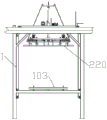
FIG. 1 is a schematic structural view of a grabbing and lifting integrated device;
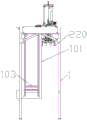
FIG. 2 is a front view of the gripping and lifting integrated device;
FIG. 3 is a left side view of the integrated gripping and lifting device;
FIG. 4 is a schematic view of the overall structure of a ferry vehicle lifting platform;
FIG. 5 is a front view of the ferry vehicle lift platform;
FIG. 6 is a right side view of the ferry vehicle lift platform;
FIG. 7 is a second schematic structural view of the elevating platform;
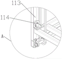
FIG. 8 is an enlarged view of A in FIG. 4;
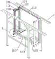
FIG. 9 is a schematic view of the overall structure of the grasping apparatus;
FIG. 10 is a schematic view of the first mid-frame and the lifting gripper assembly;
FIG. 11 is a top view of the first mid-frame and the lift gripper assembly;
FIG. 12 is a front view of the first mid-frame and the lift gripper assembly;
FIG. 13 is a driving relationship diagram of the chain wheel I, the cross, the motor III and the gripper;
fig. 14 is an enlarged view of B in fig. 10.
In the figure: 1-a portal frame;
101-inner frame, 102-lifting frame, 103-conveying table, 104-air cylinder, 105-guide rail I, 106-guide rail II, 107-clamping groove, 108-rotating shaft, 109-chain wheel, 110-vertical chain, 111-motor, 112-transverse chain, 113-sliding groove and 114-rolling wheel;
201-first middle frame, 202-first inner frame, 203-mounting plate, 204-guide column, 205-sliding sleeve, 206-gripper, 207-cylinder I, 208-pulley I, 209-rotating shaft I, 210-rotating wheel I, 211-motor I, 212-pulley II, 213-rotating shaft II, 214-rotating wheel II, 215-motor II, 216-cross, 217-motor III, 218-chain wheel I, 219-chain wheel II, 220-gripper bar, 221-crank arm, 222-connecting rod and 223-push arm.
Detailed Description
In the description of the present invention, it should also be noted that, unless otherwise explicitly specified or limited, the terms "disposed," "mounted," "connected," and "connected" are to be construed broadly, e.g., as meaning either a fixed connection, a removable connection, or an integral connection; can be mechanically or electrically connected; they may be connected directly or indirectly through intervening media, or they may be interconnected between two elements. The specific meaning of the above terms in the present invention can be understood in specific cases to those skilled in the art.
The technical solutions in the embodiments of the present invention will be described clearly and completely with reference to the accompanying drawings in the embodiments of the present invention, and it is obvious that the described embodiments are only some embodiments of the present invention, not all embodiments. Based on the embodiments in the present invention, all other embodiments obtained by a person skilled in the art without creative work belong to the protection scope of the present invention.
Example 1: as shown in fig. 1-14, a grabbing and lifting integrated device for a maintenance kiln comprises a portal frame 1, wherein a ferry vehicle lifting platform is installed on one side of the portal frame 1, which is close to a maintenance kiln, a grabbing device capable of moving along the portal frame X direction is also installed on the portal frame, the portal frame is built beside the maintenance kiln and is used in cooperation with the maintenance kiln, the ferry vehicle lifting platform can lift the ferry vehicle to maintenance kiln gates with different heights of the same maintenance kiln in a row, the ferry vehicle is sent to enter and exit the maintenance kiln, meanwhile, a partition plate dragged by a steel support plate is carried on the maintenance kiln, and the partition plate is operated to a proper position by the grabbing device to grab and send the steel support plate carrying the partition plate onto the ferry vehicle.
As shown in fig. 4-8, the ferry vehicle lifting platform comprises an inner frame 101 installed on a portal frame 1, wherein a lifting frame 102 capable of lifting along a Z direction is installed on the inner frame 101, that is, the lifting frame 102 is lifted back and forth inside the inner frame, a lifting assembly for driving the lifting frame to lift is further arranged on the inner frame, the lifting assembly comprises four rotating shafts 108 installed on the inner frame, the four rotating shafts are respectively installed above and below the left and right ends of the inner frame in parallel, the rotating shafts 108 are arranged along the Y direction, that is, rotating shafts are installed above and below the inner frame, the four rotating shafts are also distributed at the left and right ends, the rotating shafts above and below need to correspond, each rotating shaft is correspondingly provided with a chain wheel 109, a vertical chain 110 is connected between the chain wheels above and below the inner frame, a part of the vertical chain is fixed with the lifting frame, and a motor 111 for driving the rotating shafts to, the motor rotates promptly, and the axis of rotation then rotates, and the axis of rotation synchronous rotation of upper and lower place under the drive of vertical even strip, the axis of rotation at both ends is connected through horizontal chain 112 about the internal frame top simultaneously, and the axis of rotation of one side has rotated promptly, and the axis of rotation of opposite side is followed and is rotated in step, then drives whole lifting frame oscilaltion when vertical chain goes up and down. Sliding grooves 113 are formed in the inner frame corresponding to the four corners of the lifting frame along the Z direction, guide blocks capable of being inserted into the sliding grooves are installed at the four corners of the lifting frame, namely, the guide blocks can be lifted up and down in the sliding grooves in the lifting process, so that the guiding effect is achieved, in order to further optimize the scheme, the guide blocks are designed into rolling wheels 114, the four rolling wheels of the lifting frame are all in contact with the inner wall of the inner side position of the sliding grooves, namely, every two rolling wheels tightly clamp the whole lifting frame, namely, each rolling wheel is attached to the inner wall, which is the most inner side of the sliding grooves, of the inner frame, when the rolling wheels rise or fall in the sliding grooves, the rolling wheels can roll along the inner wall in a friction mode, the lifting frame rises and falls smoothly, the lifting frame is fixed in position, the front and back shaking conditions cannot occur, the cross sections of the rolling wheels are in a T shape, and the outermost, the biggest terminal surface of rolling wheel area can block in the opening part of spout promptly, and then goes up and down more firmly, and the side rocks about can not appearing.
Install on the lift frame and to carrying platform 103 that removes along Y, still install cylinder 104 on the lift frame, the drive end of cylinder 104 is connected with carrying the platform bottom, carry the bench install with ferry vehicle gyro wheel assorted guide rail 105, install guide rail two 106 on the lift frame, carry the platform bottom to be equipped with the draw-in groove 107 of card on the guide rail, the draw-in groove card of carrying the platform is on guide rail two, by cylinder propelling movement back, carry the platform to remove, a guide rail butt joint for with the curing kiln, thereby ferry vehicle on carrying the platform can move in the curing kiln.
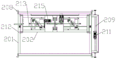
As shown in fig. 9-14, the gripping device includes a first middle frame 201 that is installed on the gantry and can move in the X direction of the gantry, a first pulley 208 that can move in the X direction of the gantry is installed on the first middle frame 201, the first pulleys are four and are respectively distributed at four corners of the first middle frame, the first pulley can travel on the gantry 1, a first rotating shaft 209 is further installed on the first middle frame 201 in the horizontal Y direction, first rotating wheels 210 corresponding to the first pulley in the horizontal direction are arranged at two ends of the first rotating shaft, a first motor 211 is further installed on the first middle frame 201, the first motor 211 is connected with the first rotating shaft 209 through a chain, that is, the first motor driving source is, the first motor drives the first rotating shaft to rotate, the first rotating wheels move in the X direction on the gantry, and the first pulley moves to drive the whole first middle frame to move horizontally. The first middle frame is provided with a first inner frame 202 capable of moving along the Y direction of the first middle frame, the first inner frame 202 is provided with a lifting gripper assembly, namely the first inner frame moves in the first middle frame and moves along the horizontal Y direction, namely the first inner frame can move above the lifting platform along the Y direction and corresponds to the lifting platform, the lifting gripper assembly can be driven to move when the first inner frame moves, when the first middle frame moves horizontally, the first inner frame and the lifting gripper assembly can be driven to move, the first inner frame is provided with a second pulley 212 capable of moving along the Y direction on the first middle frame, the second pulley 212 is also arranged at four corners of the first inner frame and is used for moving along the horizontal Y direction on the first middle frame, the first inner frame is further provided with a second rotating shaft 213 in the transverse direction (X direction), two rotating wheels 214 horizontally corresponding to the second pulley are arranged at two ends of the second rotating shaft 213, the lifting gripper assembly comprises a mounting plate 203 mounted in the middle of the first inner frame, a second motor 215 is further arranged on the mounting plate 203, the second motor 215 is connected with a second rotating shaft through a chain, namely the second motor is a driving source for the first inner frame to walk, the second motor rotates to drive the second rotating shaft to rotate, and then the second pulley drives the whole first inner frame to move and walk on the first middle frame.
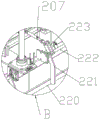
The mounting plate of the lifting gripper assembly is further provided with two guide posts 204 capable of ascending and descending along the Z direction, the mounting plate is further provided with a sliding sleeve 205 matched with the guide posts in a sleeved mode, grippers 206 are symmetrically mounted at the bottoms of the two guide posts, a first cylinder 207 for driving the grippers to stretch is mounted between the grippers 206, the guide posts 204 drive the grippers 206 to ascend and descend, meanwhile, due to the arrangement of the sliding sleeve, the guide posts can ascend and descend more smoothly, a cross 216 is arranged at the top ends of the guide posts, a motor III 217 is mounted on the mounting plate, the cross 216, the motor III 217 and the grippers 206 are connected through a chain, the top of the chain is fixed with the cross, the bottom of the chain is fixed with the grippers, the motor III rotates while the chain is meshed with the motor III 217, the whole gripper set can ascend and descend, the principle is similar to the relation between a gear and a rack, and in order to prevent the chain from sideslip, a first chain wheel 218 is further, The second chain wheel 219, the first chain wheel and the second chain wheel are vertically installed, two ends of the chain are fixed to the cross 216 and the gripper 206 respectively, and the middle of the chain sequentially passes through the first chain wheel, the third motor and the second chain wheel. The gripper comprises a gripper rod 220, at least four connecting levers 221 are vertically arranged on the gripper rod 220, a connecting rod 222 is arranged at the top end of each connecting lever, a pushing arm 223 is obliquely arranged on each connecting rod, the driving end of a first cylinder is hinged to each pushing arm, namely the first cylinder acts, the pushing arms rotate passively, the connecting rods are driven to rotate, the gripper rods at the lower ends of the connecting rods act inwards, and then the steel supporting plate can be gripped tightly. X, Y, Z directions are horizontal transverse direction, horizontal longitudinal direction and up-down lifting direction in a three-dimensional space; the first middle frame drives the whole first inner frame and the gripper assembly to walk to a proper place, the steel supporting plate at the bottommost layer is gripped, the steel supporting plate carries the partition plate, then the first middle frame moves to a row corresponding to the ferry vehicle lifting platform in the X direction, the first inner frame drives the gripper assembly and the partition plate to move to the position above the conveying platform in the Y direction, the gripper places the whole steel supporting plate with the partition plate on the ferry vehicle of the conveying platform, and then the ferry vehicle lifting platform is lifted and matched with the maintenance kiln.
Finally, it should be noted that: although the present invention has been described in detail with reference to the foregoing embodiments, it will be apparent to those skilled in the art that modifications and variations can be made in the embodiments or in part of the technical features of the embodiments without departing from the spirit and the scope of the invention.
Claims (9)
1. The utility model provides a support kiln with snatching integrative device that promotes which characterized in that: the device comprises a portal frame, wherein a ferry vehicle lifting platform is arranged on one side of the portal frame, which is close to a curing kiln, and a grabbing device capable of moving along the X direction of the portal frame is also arranged on the portal frame;
the ferry vehicle lifting platform comprises an inner frame arranged on a portal frame, a lifting frame capable of lifting along the Z direction is arranged on the inner frame, a lifting assembly used for driving the lifting frame to lift is further arranged on the inner frame, a conveying table capable of moving along the Y direction is arranged on the lifting frame, an air cylinder is further arranged on the lifting frame, the driving end of the air cylinder is connected with the bottom of the conveying table, a first guide rail matched with a roller of the ferry vehicle is arranged on the conveying table, a second guide rail is arranged on the lifting frame, and a clamping groove clamped on the second guide rail is formed in the bottom of the conveying table;
grabbing device is including setting up the first well frame that can follow portal frame X on the portal frame to the removal, be provided with on the first well frame and follow first well frame Y to the first inner frame that removes to the lift platform top, be provided with on the first inner frame and be used for snatching the steel layer board and place the lift gripper subassembly on the ferry vehicle, lift gripper subassembly is including installing in the mounting panel at first inner frame middle part, be provided with two guide posts that can follow Z to the oscilaltion on the mounting panel, still be provided with on the mounting panel and match the sliding sleeve of suit with the guide post, two guide post bottom symmetries are provided with the gripper, be provided with between the gripper and be used for driving the cylinder that the gripper stretched.
2. The integrated grabbing and lifting device for a curing kiln as claimed in claim 1, wherein: lifting unit is including installing the axis of rotation on the internal frame, the axis of rotation is four, and parallel mount is in the top and the below at both ends about the internal frame respectively, and the axis of rotation is along Y to setting up, all corresponds in every axis of rotation and installs the sprocket, is connected with vertical chain between the sprocket that internal frame top and below correspond, partly fixed with the lift frame of vertical chain, be connected with in the arbitrary axis of rotation and be used for driving axis of rotation pivoted motor, the axis of rotation at both ends is passed through horizontal chain connection about the internal frame top.
3. The integrated grabbing and lifting device for a curing kiln as claimed in claim 1, wherein: and sliding grooves are formed in the positions, corresponding to the four corners of the lifting frame, of the inner frame along the Z direction, and guide blocks capable of being inserted into the sliding grooves are arranged at the four corners of the lifting frame.
4. A grabbing and lifting integrated device for a curing kiln as claimed in claim 3, wherein: the guide block is a rolling wheel, four rolling wheels of the lifting frame are all in contact with the inner wall of the inner side of the sliding groove, the cross section of each rolling wheel is T-shaped, and the outermost end of each rolling wheel is blocked at the opening of the sliding groove.
5. The integrated grabbing and lifting device for a curing kiln as claimed in claim 1, wherein: the gantry crane is characterized in that a first pulley capable of moving in the X direction on the gantry is arranged on the first middle frame, a first rotating shaft is further arranged on the first middle frame in the horizontal Y direction, first rotating wheels horizontally corresponding to the first pulley are arranged at two ends of the first rotating shaft, and a first motor is further arranged on the first middle frame and is connected with the first rotating shaft through a chain.
6. The integrated grabbing and lifting device for a curing kiln as claimed in claim 1, wherein: the first inner frame is provided with a second pulley capable of moving in the Y direction on the first middle frame, the first inner frame is transversely provided with a second rotating shaft, two ends of the second rotating shaft are provided with second rotating wheels horizontally corresponding to the second pulleys, the mounting plate is further provided with a second motor, and the second motor is connected with the second rotating shaft through a chain.
7. The integrated grabbing and lifting device for a curing kiln as claimed in claim 1, wherein: the top of guide post is provided with the cross, be provided with motor three on the mounting panel, through the vertical connection of chain between cross, motor three, the gripper, and the chain top is fixed with the cross, and the chain bottom is fixed with the gripper.
8. A grabbing and lifting integrated device for a curing kiln as claimed in claim 7, wherein: and a first chain wheel and a second chain wheel are further arranged on one side of the third motor on the mounting plate, two ends of the chain are respectively fixed on the cross and the gripper, and the middle part of the chain sequentially passes through the first chain wheel, the third motor and the second chain wheel.
9. The integrated grabbing and lifting device for a curing kiln as claimed in claim 1, wherein: the gripper comprises a gripper rod, wherein at least four connecting levers are vertically arranged on the gripper rod, a connecting rod is arranged at the top end of each connecting lever, a pushing arm is obliquely arranged on each connecting rod, and the driving end of a first air cylinder is hinged to the pushing arm.
Priority Applications (1)
| Application Number | Priority Date | Filing Date | Title |
|---|---|---|---|
| CN201920147788.7U CN209920170U (en) | 2019-01-29 | 2019-01-29 | Grabbing and lifting integrated device for curing kiln |
Applications Claiming Priority (1)
| Application Number | Priority Date | Filing Date | Title |
|---|---|---|---|
| CN201920147788.7U CN209920170U (en) | 2019-01-29 | 2019-01-29 | Grabbing and lifting integrated device for curing kiln |
Publications (1)
| Publication Number | Publication Date |
|---|---|
| CN209920170U true CN209920170U (en) | 2020-01-10 |
Family
ID=69067961
Family Applications (1)
| Application Number | Title | Priority Date | Filing Date |
|---|---|---|---|
| CN201920147788.7U Active CN209920170U (en) | 2019-01-29 | 2019-01-29 | Grabbing and lifting integrated device for curing kiln |
Country Status (1)
| Country | Link |
|---|---|
| CN (1) | CN209920170U (en) |
-
2019
- 2019-01-29 CN CN201920147788.7U patent/CN209920170U/en active Active
Similar Documents
| Publication | Publication Date | Title |
|---|---|---|
| CN206886595U (en) | A kind of carrier automatic conveying equipment | |
| CN211733113U (en) | Wood board feeding device for floor gluing line | |
| CN111572871A (en) | New energy automobile battery packing transportation equipment | |
| CN210973030U (en) | Offline stacking production line | |
| CN109095171B (en) | Efficient plate unloading machine for multilayer foam ceramic plates | |
| CN209920169U (en) | Three-dimensional partition plate processing and maintaining system | |
| CN209920170U (en) | Grabbing and lifting integrated device for curing kiln | |
| CN110902605B (en) | Automatic stacking equipment of lithium battery module for new energy automobile | |
| CN219097195U (en) | Full-automatic cushion block supply equipment | |
| CN215358995U (en) | Superimposed shear wall turn-over device | |
| CN109648697B (en) | Three-dimensional partition plate processing maintenance system | |
| CN214269308U (en) | Clamping type stacker crane | |
| CN209600924U (en) | A kind of automatic storage tank case unpacker | |
| CN114590603A (en) | Automatic aluminum round bar stacking equipment | |
| CN210456429U (en) | Squirrel-cage type plate turnover machine | |
| CN205087856U (en) | Automatic setting machine layer board overhead hoist | |
| CN210914376U (en) | Truss type glass conveying turnover machine | |
| CN204250798U (en) | The automatic metalworking travel line of cage guide step wise | |
| CN204917383U (en) | Neat turnaround system of corrugated box automatic conveying sign indicating number | |
| CN209635256U (en) | Curing kilns ferry bus lifting device | |
| CN209812702U (en) | Novel material partition plate automation line is with tearing trigger open | |
| CN209956893U (en) | Conveying rotating table | |
| CN113148659A (en) | High-efficient unloader of foam ceramic plate | |
| CN112878666A (en) | System and method for overturning and assembling superposed shear wall | |
| CN204917143U (en) | Automatic sign indicating number of corrugated box has enough to meet need device together |
Legal Events
| Date | Code | Title | Description |
|---|---|---|---|
| GR01 | Patent grant | ||
| GR01 | Patent grant |