CN209919373U - CNC workpiece positioning device and machine tool using same - Google Patents
CNC workpiece positioning device and machine tool using same Download PDFInfo
- Publication number
- CN209919373U CN209919373U CN201920608441.8U CN201920608441U CN209919373U CN 209919373 U CN209919373 U CN 209919373U CN 201920608441 U CN201920608441 U CN 201920608441U CN 209919373 U CN209919373 U CN 209919373U
- Authority
- CN
- China
- Prior art keywords
- positioning
- workpiece
- block
- clamp
- connecting hole
- Prior art date
- Legal status (The legal status is an assumption and is not a legal conclusion. Google has not performed a legal analysis and makes no representation as to the accuracy of the status listed.)
- Withdrawn - After Issue
Links
- 239000000758 substrate Substances 0.000 claims description 35
- 239000000428 dust Substances 0.000 claims description 8
- 238000003780 insertion Methods 0.000 claims description 6
- 230000037431 insertion Effects 0.000 claims description 6
- 229910003460 diamond Inorganic materials 0.000 claims description 3
- 239000010432 diamond Substances 0.000 claims description 3
- 238000007789 sealing Methods 0.000 claims description 2
- 238000013461 design Methods 0.000 description 5
- 238000010586 diagram Methods 0.000 description 5
- XEEYBQQBJWHFJM-UHFFFAOYSA-N Iron Chemical compound [Fe] XEEYBQQBJWHFJM-UHFFFAOYSA-N 0.000 description 2
- 230000002159 abnormal effect Effects 0.000 description 2
- 230000000694 effects Effects 0.000 description 2
- 238000009434 installation Methods 0.000 description 2
- 238000000034 method Methods 0.000 description 2
- 239000002699 waste material Substances 0.000 description 2
- 230000001174 ascending effect Effects 0.000 description 1
- 230000009286 beneficial effect Effects 0.000 description 1
- 238000012937 correction Methods 0.000 description 1
- 238000004880 explosion Methods 0.000 description 1
- 229910052742 iron Inorganic materials 0.000 description 1
- 230000013011 mating Effects 0.000 description 1
- 238000012986 modification Methods 0.000 description 1
- 230000004048 modification Effects 0.000 description 1
Images


Landscapes
- Jigs For Machine Tools (AREA)
Abstract
The utility model provides a CNC work piece positioner and use lathe of this anchor clamps, including the base plate with be used for at least one anchor clamps of clamping work piece, anchor clamps pass through positioner to be fixed on the base plate, and the Y axle coordinate and the Z axle coordinate of anchor clamps location work piece are provided with the locating lever that is used for butt work piece one end in X axle direction on positioner. The utility model provides a CNC work piece positioner compares with prior art, and anchor clamps are when the clamping work piece, and the coordinate of work piece two coordinate axes on the space has been confirmed, and only the coordinate of the open end of clamping mouth of anchor clamps need be measured and rectified, and the manual work of solving the little work piece rectifies the inefficiency and bumps the problem of number inefficiency in the manual work branch. For a long-strip-shaped special workpiece, a plurality of oil pressure vices are needed to clamp the same workpiece, and the problem that clamping of double (multiple) vices for solving the special workpiece (the long-strip-shaped workpiece) is difficult to achieve.
Description
Technical Field
The utility model belongs to the technical field of anchor clamps are made, more specifically say, relate to a CNC work piece positioner and use lathe of this anchor clamps.
Background
When a workpiece is machined (clamped and clamped by an oil pressure vice for CNC), the workpiece needs to be clamped by a clamp, and meanwhile, the workpiece needs to be corrected by a meter correcting effect and counted by a centering rod (a mechanical edge finder).
The switching of the workpieces is conventionally generally: and clamping in a machine tool, manually calibrating the meter after clamping, and performing centre-to-centre counting.
However, the whole clamping process is frequently operated manually, the machine tool is in a halt state when being corrected and subjected to center-dividing and number-taking, and the actual use efficiency of the machine tool is low. When clamping of part of special workpieces (clamping of a lock plate, clamping of a magnetic disk and clamping of an oil pressure vice can be realized), the operation is difficult on site.
SUMMERY OF THE UTILITY MODEL
An object of the utility model is to provide a CNC work piece positioner to solve the problem of the lathe in-service use efficiency that exists among the prior art low, clamping difficulty when meetting special work piece.
In order to achieve the above object, the utility model adopts the following technical scheme: the utility model provides a CNC work piece positioner, includes the base plate and is used for at least one anchor clamps of clamping work piece, anchor clamps pass through positioner to be fixed on the base plate, anchor clamps location the Y axle coordinate and the Z axle coordinate of work piece, last being provided with of positioner is used for butt in the X axle direction the locating lever of work piece one end.
Further, the positioning device comprises a first positioning assembly used for positioning the Y-axis coordinate of the clamp, a second positioning assembly used for positioning the X-axis coordinate of the clamp and a third positioning assembly used for positioning the Z-axis coordinate of the clamp.
Furthermore, the first positioning assembly comprises at least one first positioning block arranged on the substrate, and a positioning groove used for accommodating the first positioning block is formed in the clamp.
Preferably, the first positioning component comprises four first positioning blocks, and the four first positioning blocks are distributed in a diamond shape.
Further, the second positioning assembly comprises two second positioning blocks arranged on the substrate, and the clamp is clamped between the two second positioning blocks in the X-axis direction.
Furthermore, at least two clamps are arranged on the substrate, and one second positioning block is shared between every two adjacent clamps.
Furthermore, the second positioning assembly further comprises a positioning column for connecting the second positioning block to the substrate, the second positioning block is provided with a plurality of positioning holes for the positioning column and the positioning column to be inserted, and the substrate is provided with insertion holes for communicating the positioning holes and the positioning column to be inserted.
Furthermore, a first positioning sleeve is sleeved in the inserting hole.
Furthermore, a second positioning sleeve is sleeved in the positioning hole, the positioning column sequentially penetrates through the second positioning sleeve and the first positioning sleeve, and the top of the positioning column is lower than the top surface of the second positioning block and higher than the bottom surface of the second positioning block.
Further, the positioning rod is inserted into the second positioning sleeve, and the top of the positioning rod is higher than the bottom surface of the workpiece.
Furthermore, the positioning column and the top of the positioning rod are fixed with a fixing rod convenient for force application.
Furthermore, the second positioning assembly further comprises a dust cover which is arranged on the second positioning block and used for sealing the positioning hole and the second positioning sleeve.
Furthermore, the second positioning assembly further comprises a first fixing piece for fixing the second positioning block on the substrate.
Furthermore, a first connecting hole for the first fixing piece to pass through is formed in the second positioning block, a second connecting hole communicated with the first connecting hole is formed in the substrate, and the first fixing piece sequentially passes through the first connecting hole and the second connecting hole.
Furthermore, the third positioning assembly comprises a plurality of pressing blocks used for pressing the clamp on the substrate and a second fixing piece used for fixing the pressing blocks on the substrate, one end of the pressing block, facing the clamp, extends outwards to form a protruding block, and a seam allowance abutted to the bottom of the protruding block is formed in the side wall of the clamp.
Further, the third positioning assembly further comprises a second fixing piece for fixing the pressing block on the substrate.
Furthermore, a third connecting hole for the second fixing piece to penetrate through is formed in the pressing block, a fourth connecting hole communicated with the third connecting hole is formed in the substrate, and the second fixing piece penetrates through the third connecting hole and the fourth connecting hole in sequence.
Furthermore, a baffle for clamping the workpiece is arranged at the clamping opening of the clamp, a convex plate is arranged on the end face of the baffle for clamping the workpiece, and a step for bearing the workpiece and enabling the workpiece and the bottom of the clamping opening to be suspended is formed between the convex plate and the baffle.
Further, the clamp adopts a vice.
Another object of the utility model is to provide a machine tool, comprises a workbench, the machine tool still includes above-mentioned CNC workpiece positioning device, the base plate is fixed on the workstation.
The utility model provides a CNC work piece positioner's beneficial effect lies in: compared with the prior art, when the clamp clamps a workpiece, the coordinates of the workpiece on two coordinate axes in space are determined, and only the coordinates of the open end of the clamping opening of the clamp need to be measured and corrected, so that the problems of low manual correction efficiency and low manual counting efficiency of the workpiece are solved. For a long-strip-shaped special workpiece, a plurality of oil pressure vices are needed to clamp the same workpiece, the problem that double (multiple) vices for clamping the special workpiece (the long-strip-shaped workpiece) are difficult to correct is solved, the clamping is quickly positioned and switched, the labor intensity of workers is reduced, the abnormal generation rate of manual operation is reduced, and the humanized and industrial design is met.
Drawings
In order to more clearly illustrate the technical solutions of the embodiments of the present invention, the drawings required for the embodiments or the prior art descriptions will be briefly introduced below, and it is obvious that the drawings in the following description are only some embodiments of the present invention, and it is obvious for those skilled in the art to obtain other drawings without inventive labor.
Fig. 1 is a schematic diagram of an explosion structure of a CNC workpiece positioning device (double oil pressure vice), which is provided by the embodiment of the present invention, and a part of the structure is not shown;
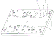
fig. 2 is a schematic structural diagram of a substrate according to an embodiment of the present invention, and a part of the structure is not shown;
fig. 3 is a schematic structural view of an oil pressure vise according to an embodiment of the present invention, and a part of the structure is not shown;
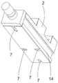
fig. 4 is a schematic structural diagram of a second positioning block according to an embodiment of the present invention, and a part of the structure is not shown;
fig. 5 is a schematic structural diagram of a pressing block provided in an embodiment of the present invention, and a partial structure is not shown;
fig. 6 is a schematic structural diagram of a baffle provided in an embodiment of the present invention, and a part of the structure is not shown.
Wherein, in the drawings, the reference numerals are mainly as follows:
1. a substrate; 2. an oil pressure vice; 3. positioning a rod;
4. a first positioning assembly; 41. a first positioning block;
5. a second positioning assembly; 51. a second positioning block; 52. a positioning column; 53. a first fixing member; 54. positioning holes; 55. a dust cover;
6. a third positioning assembly; 61. briquetting; 62. a second fixing member; 621. a bump;
7. positioning a groove; 8. inserting holes; 9. a first connection hole; 10. a second connection hole; 11. a first positioning sleeve; 12. a second positioning sleeve; 13. fixing the rod; 14. stopping the opening; 15. a third connection hole; 16. a fourth connection hole; 17. a baffle plate; 18. a convex plate; 19. a step; 20. a work bench.
Detailed Description
In order to make the technical problem, technical solution and advantageous effects to be solved by the present invention more clearly understood, the following description is given in conjunction with the accompanying drawings and embodiments to illustrate the present invention in further detail. It should be understood that the specific embodiments described herein are merely illustrative of the invention and are not intended to limit the invention.
It will be understood that when an element is referred to as being "secured to" or "disposed on" another element, it can be directly on the other element or be indirectly on the other element. When an element is referred to as being "connected to" another element, it can be directly connected to the other element or be indirectly connected to the other element.
In the description of the present invention, it is to be understood that the terms "center", "length", "width", "thickness", "upper", "lower", "front", "rear", "left", "right", "vertical", "horizontal", "top", "bottom", "inner", "outer", and the like indicate orientations or positional relationships based on those shown in the drawings, and are only for convenience of description and simplicity of description, and do not indicate or imply that the device or element referred to must have a particular orientation, be constructed and operated in a particular orientation, and therefore, should not be construed as limiting the present invention.
Furthermore, the terms "first", "second" and "first" are used for descriptive purposes only and are not to be construed as indicating or implying relative importance or implicitly indicating the number of technical features indicated. Thus, a feature defined as "first" or "second" may explicitly or implicitly include one or more of that feature. In the description of the present invention, "a plurality" means two or more unless specifically limited otherwise.
In the description of the present invention, it is to be noted that, unless otherwise explicitly specified or limited, the terms "mounted," "connected," and "connected" are to be construed broadly, and may be, for example, fixedly connected, detachably connected, or integrally connected; can be mechanically or electrically connected; either directly or indirectly through intervening media, either internally or in any other relationship. The specific meaning of the above terms in the present invention can be understood according to specific situations by those skilled in the art.
For convenience of description, three coordinate axes which are mutually vertical in space are defined as an X axis, a Y axis and a Z axis respectively, wherein the X axis and the Y axis are two coordinate axes which are mutually vertical on the same horizontal plane, and the Z axis is a coordinate axis in the vertical direction; the X axis, the Y axis and the Z axis are positioned in space and are mutually vertical, and three planes are respectively an XY plane, a YZ plane and an XZ plane, wherein the XY plane is a horizontal plane, the XZ plane and the YZ plane are vertical planes, and the XZ plane is vertical to the YZ plane.
Referring to fig. 1 and fig. 2, a CNC workpiece positioning device according to an embodiment of the present invention will be described. The CNC workpiece positioning device comprises a base plate 1 and a clamp, in the embodiment, the clamp comprises at least one oil pressure vice 2, the oil pressure vice 2 is fixed on the base plate 1 through a positioning device and used for clamping a workpiece, the clamp positions a Y-axis coordinate and a Z-axis coordinate of the workpiece, a positioning rod 3 is further arranged on the positioning device, the positioning rod 3 is used for abutting against one end portion of the workpiece in the X-axis direction, it is required to point out that X, Y, Z axes are only manually specified, and an open end of the clamped workpiece is parallel to the X axis in the embodiment.
The utility model provides a CNC work piece positioner compares with prior art, and anchor clamps are when the clamping work piece, and the coordinate of work piece two coordinate axes on the space has been confirmed, and only the coordinate of the open end of clamping mouth of anchor clamps need be measured and rectified, and the manual work of solving the little work piece rectifies the inefficiency and bumps the problem of number inefficiency in the manual work branch. For the long-strip-shaped special workpiece, a plurality of oil pressure vices 2 are needed to clamp the same workpiece, the problem that double (multi) vice clamping of the special workpiece (the long-strip-shaped workpiece) is difficult to correct is solved, the clamping is quickly positioned and switched, the labor intensity of workers is reduced, the abnormal generation rate of manual operation is reduced, and the humanized and industrial design is met.
Referring to fig. 1 and 2, the positioning device includes a first positioning assembly 4, a second positioning assembly 5 and a third positioning assembly 6. The first positioning assembly 4 is used for positioning the mounting position of the oil pressure vice 2 on the base plate 11 in the Y-axis direction, the second positioning assembly 5 is used for positioning the mounting position of the oil pressure vice 2 on the base plate 11 in the X-axis direction, the third positioning assembly 6 is used for fixing the oil pressure vice 2 on the base plate 1 in the Z-axis direction, and after the spatial position of the oil pressure vice 2 on the base plate 1 is fixed, the workpiece can be clamped. In this embodiment, the open end of the clamping opening of the oil pressure vise 2 is parallel to the X-axis direction of the base plate 1, and after the spatial position of the oil pressure vise 2 on the base plate 1 is determined, the coordinates of the workpiece in the Y-axis and Z-axis directions are determined, so that the coordinates of the workpiece in the X-axis direction only need to be measured and corrected.
Further, referring to fig. 1 and fig. 2, the first positioning assembly 4 includes at least one first positioning block 41, the hydraulic vise 2 is provided with a positioning groove 7, the first positioning block 41 is accommodated in the positioning groove 7 to position the hydraulic vise 2 in the Y-axis direction, and the hydraulic vise is simple in structure and convenient to process.
Preferably, referring to fig. 1 and fig. 2 together, as an embodiment of the present embodiment, the first positioning assembly 4 includes four first positioning blocks 41, the four first positioning blocks 41 are distributed in a diamond shape, and of course, in other embodiments, the relative positions of the first positioning blocks 41 may be selected and designed according to actual situations and needs, and a case where the connecting lines of two corresponding first positioning blocks 41 are perpendicular to the connecting lines of the other two corresponding first positioning blocks 41 is preferably selected. The number of the first positioning blocks 41 can be selected according to actual conditions and needs, for example, three first positioning blocks 41 are provided, and the triangle has stability.
The four first positioning blocks 41 are respectively fixed at four positions, namely, front and rear (hidden in fig. 1, and the installation position thereof is shown in fig. 2), left and right, on the base plate 1, and four positioning grooves 7 are correspondingly formed at the bottom of the hydraulic vise 2. After the first positioning blocks 41 and the positioning grooves 7 are engaged, the position of the hydraulic vise 2 on the substrate 1 in the Y-axis direction is determined, wherein the first positioning block 41 on the left and the first positioning block 41 on the right also function to position the hydraulic vise 2 on the substrate 1 in the X-axis direction. In this embodiment, adopt the joint mating mode of fixture block and draw-in groove to realize being connected and the location of Y axle direction ascending of oil pressure vice 2 and base plate 1, simple structure, convenient operation, the dismouting of being convenient for. Of course, in other embodiments, the fastening of the connecting member may be used instead of the snap connection.
Further, referring to fig. 1, fig. 2 and fig. 4, the second positioning assembly 5 includes a second positioning block 51, a positioning column 52 and a first fixing member 53, the second positioning block 51 is provided with a plurality of positioning holes 54, the substrate 1 is provided with an insertion hole 8 communicated with the positioning holes 54, the positioning column 52 sequentially passes through the positioning holes 54 and the insertion hole 8 to connect the second positioning block 51 and the substrate 1 together, and then the first fixing member 53 is used to tightly fix the second positioning block 51 on the substrate 1, wherein the positioning column 3 is also inserted into one of the positioning holes 54. When the second positioning blocks 51 abut against the side surfaces of the hydraulic vise 2, and when a single hydraulic vise 2 is mounted on the base plate 1, the two second positioning blocks 51 abut against the side surfaces of the hydraulic vise 2, respectively, to clamp the hydraulic vise 2, so that the mounting position of the hydraulic vise 2 on the base plate 1 in the X-axis direction is determined. In the case where the double oil pressure vise 2 or the multiple oil pressure vise 2 is mounted on the base plate 1, each second positioning block 51 is provided at an interval from each oil pressure vise 2 so that each oil pressure vise 2 remains parallel to each other after the mounting position is determined. The second positioning blocks 51 and the substrate 1 are positioned and fixed, and after each oil pressure vice 2 is sequentially clamped by each second positioning block 51, each oil pressure vice 2 does not need to be independently corrected, so that time and labor are saved, and humanized and industrial design is met.
Preferably, referring to fig. 1 to 4, in the present embodiment, the second positioning block 51 is provided with a first connecting hole 9, the substrate 1 is provided with a second connecting hole 10, the first connecting hole 9 is communicated with the second connecting hole 10, the first fixing element 53 is selected as a screw, the first connecting hole 9 and the second connecting hole 10 are also provided as threaded holes, and the second fixing element 62 and the substrate 1 are fixed together by a threaded connection manner. Of course, in other embodiments, riveting or clamping can be used instead of screwing.
Further, referring to fig. 1 and 2, the first positioning sleeve 11 is sleeved in the insertion hole 8, the first positioning sleeve 11 and the positioning column 52 are processed such that there is no gap after the positioning column 52 is inserted into the first positioning sleeve 11, that is, the positioning column 52 and the first positioning sleeve 11 are in non-gap fit, the positioning column 52 is inserted into the first positioning sleeve 11 after passing through the positioning hole 54, and the connection between the positioning column 52 and the first positioning sleeve 11 prevents the positioning column 52 from moving after positioning the second positioning block 51, so that the mounting state of the second positioning block 51 on the substrate 1 is more stable. After the positioning column 52 is inserted, the top of the positioning column is higher than the bottom surface of the second positioning block 51 and lower than the top surface of the second positioning block 51, so that subsequent measures can be taken to close the top of the second positioning block 51. As another embodiment, the top of the positioning post 52 after being inserted is flush with the top surface of the second positioning block 51 or higher than the top surface of the second positioning block 51, and the second positioning sleeve 12 inserted into the positioning post 52 no longer needs to be sealed.
Further, referring to fig. 1 and 4, the second positioning sleeve 12 is sleeved in the positioning hole 54, the second positioning sleeve 12 and the first positioning sleeve 11 are substantially the same but have different installation positions, and the positioning post 52 is inserted into the first positioning sleeve 11 to facilitate the insertion between the positioning post 52 and the first positioning sleeve 11, so as to prevent the positioning post 52 from moving after being inserted into the positioning hole 54 and being difficult to be positioned and inserted into the first positioning sleeve 11.
Further, referring to fig. 1 to 4, there are a plurality of positioning holes 54, one positioning rod 3 is inserted into one of the second positioning sleeves 12 close to the hydraulic vise 2, and a side surface of the positioning rod 3 abuts against one end surface of the open end of the workpiece. When the oil pressure vice 2 is used for clamping a workpiece, two side surfaces of the workpiece are clamped by the clamping opening of the oil pressure vice 2, two end surfaces of the workpiece are opened, the side surface of the positioning rod 3 is abutted against one end surface of the workpiece, the coordinate of the end surface on the X axis is determined, and the coordinate of the end surface on the X axis can be used as a reference number, so that the coordinate of the other end surface of the workpiece on the X axis only needs to be measured. After the positioning rod 3 is inserted into the second positioning sleeve 12, the bottom of the positioning rod 3 is higher than the bottom surface of the second positioning block 51 and the top of the positioning rod 3 is higher than the bottom surface of the workpiece.
Further, referring to fig. 1, the positioning post 52 and the top of the positioning rod 3 are fixed with a fixing rod 13 (the fixing rod 13 on the positioning post 52 is not shown in the figure), and after the positioning rod 3 is inserted into the positioning sleeve, the shape of the positioning rod 3 is regular, and it is inconvenient to directly apply force to the positioning rod 3 to take out and insert the positioning rod 3, so that the fixing post is fixed on the top of the positioning rod 3, which is convenient to find a stress point when taking out and inserting, and accords with humanized design.
Further, referring to fig. 1, the second positioning assembly 5 further includes a dust cover 55, and in the foregoing, after the positioning column 52 sequentially passes through the second positioning sleeve 12 and the first positioning sleeve 11, the top of the positioning column 52 is lower than the top of the second positioning block 51 and higher than the bottom of the second positioning block 51, so that the top of the second positioning block 51 is not closed, and waste dust such as scrap iron and the like easily enters, therefore, the dust cover 55 is used to close the top of the second positioning block 51, so as to prevent the waste dust from entering the second positioning block 51, so as to keep the inside of the second positioning block 51 clean, and meet the humanized and industrial design. As another embodiment, the top of the positioning post 52 after being inserted is flush with the top surface of the second positioning block 51 or higher than the top surface of the second positioning block 51, so that the second positioning sleeve 12 inserted into the positioning post 52 does not need to be closed by the dust cover 55.
Further, referring to fig. 1 and 5, the third positioning assembly 6 includes a plurality of pressing blocks 61 and a second fixing member 62, the pressing blocks 61 are used for pressing the oil pressure vise 2 on the substrate 1, a protrusion 621 is disposed on the pressing blocks 61, the protrusion 621 extends toward one end of the oil pressure vise 2 along the pressing blocks 61, a seam allowance 14 is disposed on a side wall of the oil pressure vise 2, and a bottom surface of the protrusion 621 abuts against the seam allowance 14 to prevent the oil pressure vise 2 from moving along the Z-axis direction. After the pressing block 61 presses the oil pressure vise 2, the pressing block 61 is fixed tightly to the substrate 1 by using the second fixing member 62.
Preferably, referring to fig. 1, fig. 2 and fig. 5, in this embodiment, a third connecting hole 15 is formed in the pressing block 61, a fourth connecting hole 16 is formed in the substrate 1, the third connecting hole 15 is communicated with the fourth connecting hole 16, the second fixing member 62 is also selected as a screw, the third connecting hole 15 and the fourth connecting hole 16 are also both formed as threaded holes, and the pressing block 61 and the substrate 1 are fixed together in a threaded manner, so that the structure is simple, the operation and the disassembly and assembly are convenient, and the implementation is easy. Of course, in other embodiments, riveting or clamping can be used instead of screwing.
Further, please refer to fig. 1 and 6, a retaining plate 17 is disposed at a clamping opening of the oil pressure vise 2, the retaining plate 17 is used for clamping a workpiece, a protruding plate 18 is disposed on an end surface of the retaining plate 17 contacting the workpiece, a step 19 is formed between the protruding plate 18 and the retaining plate 17, and a bottom surface of the workpiece abuts against the step 19 during clamping, so that the bottom of the workpiece and the bottom of the clamping opening are suspended.
Referring to fig. 1, the present invention further provides a machine tool, which comprises a worktable 20 and the above-mentioned CNC workpiece positioning device, wherein the substrate 1 of the CNC workpiece positioning device is fixed on the worktable 20.
The above description is only exemplary of the present invention and should not be taken as limiting the scope of the present invention, as any modifications, equivalents, improvements and the like made within the spirit and principles of the present invention are intended to be included within the scope of the present invention.
Claims (20)
1. The utility model provides a workpiece positioning device, includes the base plate and is used for the at least one anchor clamps of clamping work piece, anchor clamps pass through positioner to be fixed on the base plate, anchor clamps location the Y axle coordinate and the Z axle coordinate of work piece, its characterized in that: and the positioning device is provided with a positioning rod used for abutting against one end of the workpiece in the X-axis direction.
2. The workpiece positioning apparatus of claim 1, wherein: the positioning device comprises a first positioning assembly used for positioning the Y-axis coordinate of the clamp, a second positioning assembly used for positioning the X-axis coordinate of the clamp and a third positioning assembly used for positioning the Z-axis coordinate of the clamp.
3. The workpiece positioning apparatus of claim 2, wherein: the first positioning component comprises at least one first positioning block arranged on the substrate, and a positioning groove used for accommodating the first positioning block is formed in the clamp.
4. A workpiece positioning device as defined in claim 3, characterized in that: the first positioning component comprises four first positioning blocks which are distributed in a diamond shape.
5. The workpiece positioning apparatus of claim 2, wherein: the second positioning assembly comprises two second positioning blocks arranged on the substrate, and the clamp is clamped between the two second positioning blocks in the X-axis direction.
6. The apparatus according to claim 5, wherein at least two jigs are provided on the base plate, and one second positioning block is shared between two adjacent jigs.
7. The workpiece positioning apparatus of claim 5, wherein: the second positioning assembly further comprises a positioning column used for connecting the second positioning block to the substrate, the second positioning block is provided with a plurality of positioning holes for the positioning column and the positioning column to be inserted, and the substrate is provided with insertion holes communicated with the positioning holes and used for the positioning column to be inserted.
8. The workpiece positioning apparatus of claim 7, wherein: the plug hole is internally sleeved with a first positioning sleeve.
9. The workpiece positioning apparatus of claim 8, wherein: the locating hole is internally provided with a second locating sleeve in a sleeved mode, the locating column sequentially penetrates through the second locating sleeve and the first locating sleeve, and the top of the locating column is lower than the top surface of the second locating block and higher than the bottom surface of the second locating block.
10. The workpiece positioning apparatus of claim 9, wherein: the positioning rod is inserted into the second positioning sleeve, and the top of the positioning rod is higher than the bottom surface of the workpiece.
11. The workpiece positioning apparatus of claim 10, wherein: and the top parts of the positioning column and the positioning rod are fixedly provided with fixing rods convenient for force application.
12. The workpiece positioning apparatus of claim 9, wherein: the second positioning assembly further comprises a dust cover which is arranged on the second positioning block and used for sealing the positioning hole and the second positioning sleeve.
13. The workpiece positioning apparatus of claim 5, wherein: the second positioning assembly further comprises a first fixing piece used for fixing the second positioning block on the base plate.
14. The workpiece positioning apparatus of claim 13, wherein: the second positioning block is provided with a first connecting hole for the first fixing piece to pass through, the substrate is provided with a second connecting hole communicated with the first connecting hole, and the first fixing piece sequentially passes through the first connecting hole and the second connecting hole.
15. The workpiece positioning apparatus of claim 2, wherein: the third positioning assembly comprises a plurality of pressing blocks used for pressing the clamp on the substrate, one end of each pressing block, facing the clamp, extends outwards to form a convex block, and the side wall of the clamp is provided with a spigot abutted to the bottom of the convex block.
16. The workpiece positioning apparatus of claim 15, wherein: the third positioning assembly further comprises a second fixing piece used for fixing the pressing block on the substrate.
17. The workpiece positioning apparatus of claim 16, wherein: the pressing block is provided with a third connecting hole for the second fixing piece to penetrate through, the substrate is provided with a fourth connecting hole communicated with the third connecting hole, and the second fixing piece penetrates through the third connecting hole and the fourth connecting hole in sequence.
18. The workpiece positioning apparatus of claim 1, wherein: the clamp is characterized in that a baffle for clamping the workpiece is arranged at the clamping opening of the clamp, a convex plate is arranged on the end face of the baffle for clamping the workpiece, and a step for bearing the workpiece and enabling the workpiece and the bottom of the clamping opening to be suspended is formed between the convex plate and the baffle.
19. The workpiece positioning apparatus of claim 1, wherein the fixture is a vise.
20. A machine tool comprising a table, characterized in that: further comprising a workpiece positioning device as defined in any of claims 1-19, said base plate being fixed to said stage.
Priority Applications (1)
| Application Number | Priority Date | Filing Date | Title |
|---|---|---|---|
| CN201920608441.8U CN209919373U (en) | 2019-04-29 | 2019-04-29 | CNC workpiece positioning device and machine tool using same |
Applications Claiming Priority (1)
| Application Number | Priority Date | Filing Date | Title |
|---|---|---|---|
| CN201920608441.8U CN209919373U (en) | 2019-04-29 | 2019-04-29 | CNC workpiece positioning device and machine tool using same |
Publications (1)
| Publication Number | Publication Date |
|---|---|
| CN209919373U true CN209919373U (en) | 2020-01-10 |
Family
ID=69089037
Family Applications (1)
| Application Number | Title | Priority Date | Filing Date |
|---|---|---|---|
| CN201920608441.8U Withdrawn - After Issue CN209919373U (en) | 2019-04-29 | 2019-04-29 | CNC workpiece positioning device and machine tool using same |
Country Status (1)
| Country | Link |
|---|---|
| CN (1) | CN209919373U (en) |
Cited By (1)
| Publication number | Priority date | Publication date | Assignee | Title |
|---|---|---|---|---|
| CN110216500A (en) * | 2019-04-29 | 2019-09-10 | 珠海格力精密模具有限公司 | CNC Working piece positioning device and the lathe for using the fixture |
-
2019
- 2019-04-29 CN CN201920608441.8U patent/CN209919373U/en not_active Withdrawn - After Issue
Cited By (2)
| Publication number | Priority date | Publication date | Assignee | Title |
|---|---|---|---|---|
| CN110216500A (en) * | 2019-04-29 | 2019-09-10 | 珠海格力精密模具有限公司 | CNC Working piece positioning device and the lathe for using the fixture |
| CN110216500B (en) * | 2019-04-29 | 2024-01-26 | 珠海格力精密模具有限公司 | CNC work piece positioner and use lathe of this anchor clamps |
Similar Documents
| Publication | Publication Date | Title |
|---|---|---|
| CN102922316A (en) | Machining fixture for objective lens connecting plates | |
| CN209919373U (en) | CNC workpiece positioning device and machine tool using same | |
| CN215510021U (en) | Quick positioner in inclined plane | |
| CN110216500B (en) | CNC work piece positioner and use lathe of this anchor clamps | |
| CN104625811A (en) | Device applying bench drill for machining precise-pitch holes and machining method of device | |
| CN213645980U (en) | Double-flange workpiece drilling tool | |
| CN204639673U (en) | A kind of multi-work piece clamp for machining | |
| CN209936729U (en) | Miniature profiling vice | |
| CN209425018U (en) | It is machined Quick-positioning clamp platform | |
| CN215239312U (en) | General forked tail anchor clamps that use on five machining centers | |
| CN217394337U (en) | Special fixture for joint part of mechanical arm | |
| CN219665798U (en) | Concentric milling fixture for top surfaces of two angle surface holes | |
| CN216990888U (en) | Return needle adds clamping apparatus | |
| CN216802553U (en) | High-precision clamp tool for metal piece of automatic equipment | |
| CN218253948U (en) | Lathe fixture | |
| CN212444886U (en) | Solenoid valve positioning fixture | |
| CN218926765U (en) | Skylight stay tube connector adds clamping apparatus | |
| CN111618629A (en) | Clamping device suitable for special-shaped workpiece and using method thereof | |
| CN214323127U (en) | Automatic clamping frock of changing | |
| CN215035446U (en) | Milling needle groove combination tool | |
| CN212122448U (en) | Clamp for machining | |
| CN204430872U (en) | The device in application bench drill processing precise pitch-row hole | |
| CN210549585U (en) | Be applied to anchor clamps of work piece drilling processing | |
| CN213828002U (en) | Novel special clamp for machining | |
| CN215090715U (en) | Turning auxiliary clamp for right-angle elbow, tee joint or four-way casting blank |
Legal Events
| Date | Code | Title | Description |
|---|---|---|---|
| GR01 | Patent grant | ||
| GR01 | Patent grant | ||
| AV01 | Patent right actively abandoned |
Granted publication date: 20200110 Effective date of abandoning: 20240126 |
|
| AV01 | Patent right actively abandoned |
Granted publication date: 20200110 Effective date of abandoning: 20240126 |
|
| AV01 | Patent right actively abandoned | ||
| AV01 | Patent right actively abandoned |