CN209887151U - Workpiece clamp for vertical machining center - Google Patents
Workpiece clamp for vertical machining center Download PDFInfo
- Publication number
- CN209887151U CN209887151U CN201920659059.XU CN201920659059U CN209887151U CN 209887151 U CN209887151 U CN 209887151U CN 201920659059 U CN201920659059 U CN 201920659059U CN 209887151 U CN209887151 U CN 209887151U
- Authority
- CN
- China
- Prior art keywords
- clamping
- base
- fixed
- piece
- groove
- Prior art date
- Legal status (The legal status is an assumption and is not a legal conclusion. Google has not performed a legal analysis and makes no representation as to the accuracy of the status listed.)
- Expired - Fee Related
Links
Images


Landscapes
- Jigs For Machine Tools (AREA)
Abstract
The utility model discloses a vertical machining center is with work piece holder relates to machining technical field. The utility model comprises a base, wherein a first chute is arranged on one surface of the base; the inner surface of the first sliding chute is in sliding fit with two clamping pieces; two lower pressing pieces are respectively matched on the surfaces of the two clamping pieces in a sliding way; the arrays on the two sides of the base are provided with clamping pieces; the array on one surface of the base is provided with first rectangular grooves; a first spring is fixed at the bottom of the inner wall of the first rectangular groove; through holes communicated with the first rectangular groove are formed in the two side face arrays of the base; the inner surface of the through hole is provided with a notch; two side surfaces of the lower pressing piece are provided with second sliding blocks; one end of the lower pressing piece is fixed with a pressing rod. The utility model discloses a cooperation of base, holder, holding down piece and joint spare is used, pushes down the fixture block joint that press the depression bar messenger draw-in groove and joint spare one end and carries out quick fixed to splint, is convenient for dismantle the installation to the work piece holder of splint centre gripping, and convenient operation has improved the efficiency of work piece processing.
Description
Technical Field
The utility model belongs to the technical field of machining, especially, relate to a vertical machining center is with work piece holder.
Background
The vertical machining center is a machining center with the axis of a main shaft perpendicular to a workbench, the vertical machining center can complete the processes of milling, boring, drilling, tapping and the like, a workpiece is clamped on the machining center once, the machining center can sequentially complete the machining of multiple processes on multiple surfaces of the workpiece, and the vertical machining center has multiple tool changing or selecting functions and is high in production efficiency.
In order to ensure the stability of a workpiece to be machined in the machining process, workpiece clamps are usually installed at two ends of a workbench, the existing clamps are usually fixed by adopting a bolt fastening method, a plurality of bolts are required to be fastened simultaneously to ensure the fixation of the workpiece, the operation is complex, the clamp is inconvenient for a user to use, and the practicability of the workpiece clamp for a vertical machining center is reduced.
SUMMERY OF THE UTILITY MODEL
An object of the utility model is to provide a workpiece clamp for vertical machining center has solved current workpiece clamp for vertical machining center and has adopted the problem that the bolt fastening operation is complicated, the operation is inconvenient.
In order to solve the technical problem, the utility model discloses a realize through following technical scheme:
the utility model relates to a workpiece clamp for a vertical machining center, which comprises a base, wherein a first chute is arranged on one surface of the base; the inner surface of the first sliding chute is in sliding fit with two clamping pieces; two lower pressing pieces are respectively in sliding fit with one surface of each clamping piece; the arrays on the two sides of the base are provided with clamping pieces; the clamping piece is clamped with the lower piece;
the array on one surface of the base is provided with first rectangular grooves; a first spring is fixed at the bottom of the inner wall of the first rectangular groove; through holes communicated with the first rectangular groove are formed in the two side face arrays of the base; the inner surface of the through hole is provided with a notch;
a clamping groove is formed in one side face of the lower pressing piece; two side surfaces of the lower pressing piece are provided with second sliding blocks; and one end of the lower pressing piece is fixedly provided with a pressing rod.
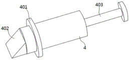
Furthermore, a limiting ring is fixed on the peripheral side surface of the clamping piece; a clamping block matched with the clamping groove is fixed at one end of the clamping piece; and a pull rod is fixed at the other end of the clamping piece.
Further, the clamping piece comprises a fixing block; a first sliding block is fixed at the bottom of the fixed block; two second rectangular grooves matched with the lower pressing piece are formed in one surface of the fixed block; the opposite side surfaces of the second rectangular grooves are provided with second sliding grooves; and a clamping plate is fixed on one side of the clamping piece.
Furthermore, the peripheral side face of the clamping piece is sleeved with a second spring between the limiting ring and the notch.
Furthermore, the bottom of the lower pressing piece is provided with a guide groove; the guide groove is communicated with the clamping groove.
The utility model discloses following beneficial effect has:
the utility model discloses a cooperation of base, holder, holding down piece and joint spare is used, pushes down the fixture block joint that press the depression bar messenger draw-in groove and joint spare one end and carries out quick fixed to splint, is convenient for dismantle the installation to the work piece holder of splint centre gripping, and convenient operation has improved the efficiency of work piece processing.
Of course, it is not necessary for any particular product to achieve all of the above-described advantages at the same time.
Drawings
In order to more clearly illustrate the technical solutions of the embodiments of the present invention, the drawings used in the description of the embodiments will be briefly introduced below, and it is obvious that the drawings in the following description are only some embodiments of the present invention, and it is obvious for those skilled in the art that other drawings can be obtained according to these drawings without creative efforts.
FIG. 1 is a schematic structural view of a workpiece holder for a vertical machining center according to the present invention;
FIG. 2 is a sectional view of a workpiece holder for a vertical machining center;
FIG. 3 is an enlarged view of a portion A of FIG. 2;
FIG. 4 is a schematic view of the hold-down;
FIG. 5 is a schematic structural view of the clip;
in the drawings, the components represented by the respective reference numerals are listed below:
1-base, 2-clamping piece, 3-lower piece, 4-clamping piece, 101-first sliding groove, 102-first rectangular groove, 103-first spring, 104-through hole, 105-notch, 201-fixed block, 202-first sliding block, 203-second rectangular groove, 204-second sliding groove, 205-clamping plate, 301-clamping groove, 302-second sliding block, 303-pressing rod, 304-guide groove, 401-limiting ring, 402-clamping block, 403-pull rod and 404-second spring.
Detailed Description
The technical solutions in the embodiments of the present invention will be described clearly and completely with reference to the accompanying drawings in the embodiments of the present invention, and it is obvious that the described embodiments are only some embodiments of the present invention, not all embodiments. Based on the embodiments of the present invention, all other embodiments obtained by a person of ordinary skill in the art without creative efforts belong to the protection scope of the present invention.
Referring to fig. 1-5, the present invention relates to a workpiece fixture for a vertical machining center, which includes a base 1, wherein a first sliding groove 101 is formed on a surface of the base 1; the inner surface of the first sliding chute 101 is in sliding fit with two clamping pieces 2; two lower pressing pieces 3 are respectively matched with one surface of each of the two clamping pieces 2 in a sliding way; the arrays on the two sides of the base 1 are provided with clamping pieces 4; the clamping piece 4 is clamped with the lower piece 3;
a first rectangular groove 102 is formed in the array on one surface of the base 1; a first spring 103 is fixed at the bottom of the inner wall of the first rectangular groove 102; through holes 104 communicated with the first rectangular groove 102 are formed in the two side faces of the base 1 in an array mode; the inner surface of the through hole 104 is provided with a notch 105;
a clamping groove 301 is formed in one side face of the lower pressing piece 3; two side surfaces of the lower pressing piece 3 are provided with second sliding blocks 302; a pressing rod 303 is fixed to one end of the lower press 3.
As shown in fig. 3, a limiting ring 401 is fixed on the peripheral side surface of the clamping member 4; a clamping block 402 matched with the clamping groove 301 is fixed at one end of the clamping piece 4; the other end of the clip 4 is fixed with a pull rod 403.
As shown in fig. 1 and 2, the clamping member 2 includes a fixing block 201; a first sliding block 202 is fixed at the bottom of the fixed block 201; one surface of the fixed block 201 is provided with two second rectangular grooves 203 matched with the lower pressing piece 3; one opposite side surface of the second rectangular groove 203 is provided with a second sliding groove 204; a clamping plate 205 is fixed on one side of the clamping piece 2.
As shown in fig. 3, a second spring 404 is sleeved on the peripheral side of the clip 4 and between the limiting ring 402 and the notch 105.
As shown in fig. 3, the bottom of the lower pressing member 3 is provided with a guide groove 304; the guide groove 304 communicates with the card groove 301.
One specific application of this embodiment is: when a workpiece to be processed is clamped, the two clamping pieces 2 are moved, the two clamping pieces 2 clamp the workpiece to be processed respectively, the pressing rod 303 is pressed downwards, the pressing rod 303 drives the pressing piece 4, the clamping block 402 is jacked up by the guide groove 304 of the pressing piece 4, and the second spring 404 is compressed, so that the clamping groove 301 is clamped with the clamping block 402 to fix the clamping plate 205.
In the description herein, references to the description of "one embodiment," "an example," "a specific example," etc., mean that a particular feature, structure, material, or characteristic described in connection with the embodiment or example is included in at least one embodiment or example of the invention. In this specification, the schematic representations of the terms used above do not necessarily refer to the same embodiment or example. Furthermore, the particular features, structures, materials, or characteristics described may be combined in any suitable manner in any one or more embodiments or examples.
The preferred embodiments of the present invention disclosed above are intended only to help illustrate the present invention. The preferred embodiments are not intended to be exhaustive or to limit the invention to the precise embodiments disclosed. Obviously, many modifications and variations are possible in light of the above teaching. The embodiments were chosen and described in order to best explain the principles of the invention and its practical applications, to thereby enable others skilled in the art to best understand the invention for and utilize the invention. The present invention is limited only by the claims and their full scope and equivalents.
Claims (5)
1. The utility model provides a vertical machining center is with work piece holder, includes base (1), its characterized in that:
a first sliding groove (101) is formed in one surface of the base (1); a plurality of clamping pieces (2) are matched on the inner surface of the first sliding chute (101) in a sliding manner; a plurality of lower pressing pieces (3) are matched on the surfaces of the plurality of clamping pieces (2) in a sliding way; clamping pieces (4) are arranged on the two side arrays of the base (1); the clamping piece (4) is clamped with the lower pressing piece (3);
a first rectangular groove (102) is formed in one surface of the base (1) in an array manner; a first spring (103) is fixed at the bottom of the inner wall of the first rectangular groove (102); through holes (104) communicated with the first rectangular groove (102) are formed in the two side arrays of the base (1); the inner surface of the through hole (104) is provided with a notch (105);
a clamping groove (301) is formed in one side face of the lower pressing piece (3); two side surfaces of the lower pressing piece (3) are provided with second sliding blocks (302); one end of the lower pressing piece (3) is fixed with a pressing rod (303).
2. The workpiece clamp for the vertical machining center according to claim 1, wherein a limiting ring (401) is fixed on the peripheral side surface of the clamping member (4); a clamping block (402) matched with the clamping groove (301) is fixed at one end of the clamping piece (4); and a pull rod (403) is fixed at the other end of the clamping piece (4).
3. A workpiece holder for a vertical machining center according to claim 1, characterized in that the holder (2) comprises a fixed block (201); a first sliding block (202) is fixed at the bottom of the fixed block (201); one surface of the fixed block (201) is provided with two second rectangular grooves (203) matched with the lower pressing piece (3); one opposite side surface of the second rectangular groove (203) is provided with a second sliding groove (204); a clamping plate (205) is fixed on one side of the clamping piece (2).
4. The workpiece clamp for the vertical machining center according to claim 1, wherein a second spring (404) is sleeved on the peripheral side surface of the clamping piece (4) and between the limiting ring (401) and the notch (105).
5. A workpiece holder for a vertical machining center according to claim 1, wherein the bottom of the lower member (3) is provided with a guide groove (304); the guide groove (304) is communicated with the clamping groove (301).
Priority Applications (1)
| Application Number | Priority Date | Filing Date | Title |
|---|---|---|---|
| CN201920659059.XU CN209887151U (en) | 2019-05-09 | 2019-05-09 | Workpiece clamp for vertical machining center |
Applications Claiming Priority (1)
| Application Number | Priority Date | Filing Date | Title |
|---|---|---|---|
| CN201920659059.XU CN209887151U (en) | 2019-05-09 | 2019-05-09 | Workpiece clamp for vertical machining center |
Publications (1)
| Publication Number | Publication Date |
|---|---|
| CN209887151U true CN209887151U (en) | 2020-01-03 |
Family
ID=69020470
Family Applications (1)
| Application Number | Title | Priority Date | Filing Date |
|---|---|---|---|
| CN201920659059.XU Expired - Fee Related CN209887151U (en) | 2019-05-09 | 2019-05-09 | Workpiece clamp for vertical machining center |
Country Status (1)
| Country | Link |
|---|---|
| CN (1) | CN209887151U (en) |
Cited By (2)
| Publication number | Priority date | Publication date | Assignee | Title |
|---|---|---|---|---|
| CN111408965A (en) * | 2020-05-07 | 2020-07-14 | 宁波引智信息科技有限公司 | Machine tool equipment with conveniently adjust anchor clamps function |
| CN112847192A (en) * | 2020-12-31 | 2021-05-28 | 深圳长城开发精密技术有限公司 | Hard disk substrate quick-change clamp |
-
2019
- 2019-05-09 CN CN201920659059.XU patent/CN209887151U/en not_active Expired - Fee Related
Cited By (2)
| Publication number | Priority date | Publication date | Assignee | Title |
|---|---|---|---|---|
| CN111408965A (en) * | 2020-05-07 | 2020-07-14 | 宁波引智信息科技有限公司 | Machine tool equipment with conveniently adjust anchor clamps function |
| CN112847192A (en) * | 2020-12-31 | 2021-05-28 | 深圳长城开发精密技术有限公司 | Hard disk substrate quick-change clamp |
Similar Documents
| Publication | Publication Date | Title |
|---|---|---|
| CN201483263U (en) | Non-standard flexible butt clamping device | |
| CN209887151U (en) | Workpiece clamp for vertical machining center | |
| CN103753297A (en) | Bar fixture | |
| CN215967520U (en) | Milling rapid clamping fixture | |
| CN215616550U (en) | Clamp for multi-station processing machine tool | |
| CN214488973U (en) | Frock clamp that mould processing milling machine was used | |
| CN2803612Y (en) | Positioned gripping jaw base assembly | |
| CN209774066U (en) | Multifunctional clamp | |
| CN216371155U (en) | A anchor clamps platform for machine tool machining | |
| CN212286793U (en) | Anticreep ring location frock | |
| CN212526912U (en) | End cover mills a boring grab | |
| CN214444676U (en) | Integral type frock clamp | |
| CN111618629A (en) | Clamping device suitable for special-shaped workpiece and using method thereof | |
| CN213970802U (en) | Standard angle pushes up fast machining anchor clamps to one side | |
| CN218656292U (en) | Fixed fixture of servo punch press | |
| CN218193921U (en) | Combined rotary clamp | |
| CN220178667U (en) | Drilling and fixing device for milling groove of pad cover | |
| CN215317141U (en) | Five quick clamping general frocks in longmen | |
| CN212240082U (en) | Fork shaft type drilling clamp | |
| CN218592363U (en) | Zero positioning base convenient for replacing clamp | |
| CN213469695U (en) | Clamp for processing hole of support plate of automobile battery valve | |
| CN214770496U (en) | Clamp for bottom plate | |
| CN213828002U (en) | Novel special clamp for machining | |
| CN216178605U (en) | CNC is centre gripping frock for machining | |
| CN217452182U (en) | Novel comprehensive claw centre gripping of locating piece type device |
Legal Events
| Date | Code | Title | Description |
|---|---|---|---|
| GR01 | Patent grant | ||
| GR01 | Patent grant | ||
| CF01 | Termination of patent right due to non-payment of annual fee | ||
| CF01 | Termination of patent right due to non-payment of annual fee |
Granted publication date: 20200103 |