CN203667440U - Fiber pump for conveying fiber materials - Google Patents
Fiber pump for conveying fiber materials Download PDFInfo
- Publication number
- CN203667440U CN203667440U CN201320809701.0U CN201320809701U CN203667440U CN 203667440 U CN203667440 U CN 203667440U CN 201320809701 U CN201320809701 U CN 201320809701U CN 203667440 U CN203667440 U CN 203667440U
- Authority
- CN
- China
- Prior art keywords
- feeding
- fiber
- smart
- blending bunker
- conveying
- Prior art date
- Legal status (The legal status is an assumption and is not a legal conclusion. Google has not performed a legal analysis and makes no representation as to the accuracy of the status listed.)
- Expired - Lifetime
Links
- 239000000835 fiber Substances 0.000 title claims abstract description 44
- 239000002657 fibrous material Substances 0.000 title claims abstract description 17
- 238000002156 mixing Methods 0.000 claims abstract description 33
- 239000000463 material Substances 0.000 claims abstract description 17
- 238000007599 discharging Methods 0.000 claims abstract description 7
- 238000002955 isolation Methods 0.000 claims abstract description 5
- 125000003003 spiro group Chemical group 0.000 claims description 25
- 238000007664 blowing Methods 0.000 claims description 18
- 238000005520 cutting process Methods 0.000 claims description 14
- 230000035939 shock Effects 0.000 claims description 6
- 238000003860 storage Methods 0.000 claims description 4
- 230000005540 biological transmission Effects 0.000 claims description 3
- 238000010276 construction Methods 0.000 abstract description 7
- 239000006185 dispersion Substances 0.000 abstract description 4
- 238000013016 damping Methods 0.000 abstract 1
- 239000004576 sand Substances 0.000 description 11
- 230000000694 effects Effects 0.000 description 7
- 238000000034 method Methods 0.000 description 7
- 239000012530 fluid Substances 0.000 description 4
- 238000010586 diagram Methods 0.000 description 3
- 238000005516 engineering process Methods 0.000 description 2
- XQCFHQBGMWUEMY-ZPUQHVIOSA-N Nitrovin Chemical compound C=1C=C([N+]([O-])=O)OC=1\C=C\C(=NNC(=N)N)\C=C\C1=CC=C([N+]([O-])=O)O1 XQCFHQBGMWUEMY-ZPUQHVIOSA-N 0.000 description 1
- 230000009286 beneficial effect Effects 0.000 description 1
- 230000015572 biosynthetic process Effects 0.000 description 1
- 238000013329 compounding Methods 0.000 description 1
- 230000007774 longterm Effects 0.000 description 1
- 239000000203 mixture Substances 0.000 description 1
- 238000003825 pressing Methods 0.000 description 1
- 230000001737 promoting effect Effects 0.000 description 1
- 239000000725 suspension Substances 0.000 description 1
Images


Abstract
The utility model discloses a fiber pump for conveying fiber materials. The fiber pump comprises a charging bin (1), a spiral feeding device, a material mixing bin, a diesel engine (19), an air blower (17), a damping support, an air inlet pipe (2) and a discharging pipe (3). The spiral feeding device comprises a driving motor (4), a feeding pipe (5) and a feeding screw rod (6), the feeding screw rod (6) is arranged in an inner cavity of a feeding cylinder and is connected with the driving motor (4), the air inlet pipe (2) and the discharging pipe (3) are arranged on the two opposite side walls of the material mixing bin respectively, and an air outlet (13) of the air blower (17) is connected with the air inlet pipe of the material mixing bin through a vibration isolation hose (18). The fiber pump has the advantages that fibers are blown away through the air blast airflow, automatic control over feeding is achieved, manpower is saved, cost is reduced, the structure is simple, the dispersion efficiency is high, and the consumed time of construction is shortened.
Description
Technical field
The utility model relates to fiber fracturing, sand control is used device technique field, particularly a kind of fiber pump of conveying fiber material.
Background technology
Fiber fracturing sand control technique is after disperseing in fracturing fluid by fiber, to produce superpower suspension prop-carrying capacity and proppant crystallized ability, thus realize fractured well fast, the efficient row of returning, fundamentally prevent proppant backflow to shake out and formation sand flow; Can effectively keep the long-term flow conductivity that created fracture is higher, extend volume increase subject word; Good outstanding sand ability can be provided under low stick part, suppress that seam is high excessively to be extended simultaneously effectively, guarantee proppant in the full back-up sand of payzone section and make slit, can obtain longer supporting crack, longer volume increase subject word identical in the situation that adding sand scale.
From front described, fiber shakes out and improves aspect reservoir reconstruction effect and have good effect solving oil-gas reservoir fractured well.But fiber fracturing technology, in use procedure in early stage, has also run into sizable technical risk.If be first add that sand fiber is not pre-dispersed before use can the dispersion effect of impact in fracturing fluid, therefore cause the outstanding grittiness can be bad, and easily cause and in work progress, occur sand plug.Fiber fracturing sand control construction will obtain good effect of field application, and one of prerequisite precondition is exactly fiber and fracturing fluid can be fully, evenly mix.Therefore, how evenly, be mixed into key with fracturing fluid fiber effectively.Secondly, the manual pre-dispersed fiber of the main employing of fiber fracturing construction in early stage, causes fiber to add density unevenness, and in fracturing process, fiber dosage part is too high, has increased construction risk, greatly reduces the result of use of fiber in pressure break, sand control process.Therefore in fiber fracturing, sand control process, be necessary to develop a kind of fibre material load transfer device promoting the use of.
Utility model content
The purpose of this utility model is to overcome the shortcoming of prior art, and a kind of fiber pump of simple in structure, conveying fiber material that dispersion efficiency is high is provided.
The purpose of this utility model is achieved through the following technical solutions: a kind of fiber pump of conveying fiber material, it comprises feeding chamber, spiral feeder, blending bunker, diesel motor, blowing engine, shock bracket, blast pipe and discharge nozzle, described spiral feeder comprises drive motor, feed pipe and feeding spiro rod, feeding chamber is installed on the top of the feed end of feed pipe, on feed pipe, be provided with the inlet point that is communicated with feeding chamber, feeding spiro rod is installed in the inner chamber of feed cylinder and connects drive motor, the bottom of blending bunker feed cylinder, on feed cylinder, be provided with the discharging opening that is communicated with blending bunker, blast pipe is divided on two sidewalls that blending bunker is relative with discharge nozzle, described shock bracket comprises the several bumpers that are arranged on bench board and the support plate being supported by described bumper, diesel motor and blowing engine are all fixedly installed on support plate, and the input shaft connection for transmission of the output shaft of diesel motor and blowing engine, the air outlet of blowing engine is connected with the blast pipe of blending bunker by vibration isolation flexible pipe.
On described feeding spiro rod, be provided with feeding screw blade, single-point hangoff receptacle is installed in feed cylinder, single-point hangoff receptacle is installed in feed cylinder by bolt, take the direction of feeding spiro rod convey materials as front, the front end of feeding spiro rod is installed on single-point hangoff receptacle by bearing, the rear end of feeding spiro rod connects drive motor, is positioned on the feeding spiro rod of single-point hangoff receptacle rear side antispin blade is installed, and the hand of spiral of antispin blade is contrary with the hand of spiral of feeding screw blade.
Described blast pipe comprises cylindrical shell and cutting a smart figure, and the rear end of cutting a smart figure is connected with the forward end seal of cylindrical shell, and described cuts a smart figure for cylindrical or conical, on the front end face of cutting a smart figure, is provided with air outlet.
Described cuts a smart figure for taper shape, and on the sidewall of cutting a smart figure, edge circumferentially offers multiple exhaust vents.
In described air outlet, be provided with two and be the baffle plates that " V " type arranges, baffle plate is parallel with the axis of cutting a smart figure or acutangulate setting.
In described air outlet, be provided with baffle plate, baffle plate is the sheet material of circular arc or curve shape.
Described blending bunker is made up of the connecting portion being interconnected and cylindrical portion, and connecting portion is communicated with blending bunker and cylindrical portion, and blast pipe and discharge nozzle are divided on two axial ends of cylindrical portion, and it is up-small and down-big tubaeform that described connecting portion is.
It also comprises control housing, and controller is installed in control housing, and transmitter is installed in blending bunker, and transmitter connects controller, and controller connects revolution controller and frequency-variable controller, and revolution controller connects blowing engine, and frequency-variable controller connects drive motor.
Described transmitter comprises pressure transformer and temperature transmitter.
It also comprises for startup storage battery and electrical generator to control housing power supply.
The utlity model has following advantage:
The utility model is realized and is dispelled fiber by air blast, and has realized the automation control of feeding.
Antispin blade of the present utility model is to the reversing sense pressing materials of mass transport direction, thereby the material extruding that is positioned at blending bunker top is dropped, and guaranteed that material drops from feeding spiral rod smoothly; The connecting portion of blending bunker is up-small and down-big flaring structure and has avoided falling material gathering at feed cylinder discharging opening place; Thereby, jointly reached the effect that prevents that fibre material from stopping up.
Feeding spiro rod adopts the structure of single-point hangoff receptacle, has facilitated the dismounting of feeding spiro rod, and has simplified the structure.
The utility model by setting out public attention, on the sidewall of cutting a smart figure along setting out air port on the front end face of circumferentially offering multiple exhaust vents, cutting a smart figure, baffle plate is set in air outlet, in mixing bunker, form multithread to air-flow, thereby realize to the fiber in mixing bunker carry out chopping wind to dispel and suspend, improved the degree of scatter of fiber, thereby replace manual pre-dispersed fiber operation, save manually, reduced cost, and simple in structure, dispersion efficiency is high, has shortened construction consuming time.
The utility model is realized the addition by industrial computer control material, manipulate convenient and swift, and the adjusting of the rotating speed of the revolution by blowing engine and the drive motor of spiral feeder, realize and automatically regulate blowing engine revolution according to the amount of helix transporting device conveying fiber, allow mass transport amount and air quantity reach optimum effect, degree of automation and the control accuracy of device are improved, reduce the labour intensity of operation easier and operating personal, be beneficial to and improve construction quality, shorten the engineering time and reduce construction cost.
Accompanying drawing explanation
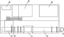
Fig. 1 is structural representation of the present utility model
Fig. 2 is plan structure schematic diagram of the present utility model
Fig. 3 is the structural representation of spiral feeder of the present utility model
Fig. 4 is the cutaway view of Fig. 3 along A-A cross section
Fig. 5 is the cutaway view of Fig. 3 along B-B cross section
Fig. 6 is the structural representation of blast pipe of the present utility model
Fig. 7 is the right TV structure schematic diagram of blast pipe of the present utility model
Fig. 8 is the right TV structure schematic diagram of the another kind of structure of blast pipe of the present utility model
In figure, 1-feeding chamber, 2-blast pipe, 3-discharge nozzle, 4-drive motor, 5-feed pipe, 6-feeding spiro rod, 7-feeding screw blade, 8-single-point hangoff receptacle, 9-antispin blade, 10-cylindrical shell, 11-cuts a smart figure, 12-exhaust vent, 13-air outlet, 14-baffle plate, 15-connecting portion, 16-cylindrical portion, 17-blowing engine, 18-vibration isolation flexible pipe, 19-diesel motor, 20-bumper, 21-support plate, 22-control housing, 23-starts storage battery, 24-electrical generator.
The specific embodiment
Below in conjunction with accompanying drawing, the utility model is further described, protection domain of the present utility model is not limited to the following stated:
As Fig. 1, shown in Fig. 2, a kind of fiber pump of conveying fiber material, it comprises feeding chamber 1, spiral feeder, blending bunker, diesel motor 19, blowing engine 17, shock bracket, blast pipe 2 and discharge nozzle 3, described spiral feeder comprises drive motor 4, feed pipe 5 and feeding spiro rod 6, feeding chamber 1 is installed on the top of the feed end of feed pipe 5, on feed pipe 5, be provided with the inlet point that is communicated with feeding chamber 1, feeding spiro rod 6 is installed in the inner chamber of feed cylinder and connects drive motor 4, blending bunker is installed on the bottom that is positioned at the feed cylinder between feeding screw blade 7 and antispin blade 9, on feed cylinder, be provided with the discharging opening that is communicated with blending bunker, blast pipe 2 is divided on two sidewalls that blending bunker is relative with discharge nozzle 3, described shock bracket comprises the several bumpers 20 that are arranged on bench board and the support plate 21 being supported by described bumper 20, diesel motor 19 and blowing engine 17 are all fixedly installed on support plate 21, and the input shaft connection for transmission of the output shaft of diesel motor 19 and blowing engine 17, the air outlet 13 of blowing engine 17 is connected with the blast pipe 2 of blending bunker by vibration isolation flexible pipe 18.
As shown in Fig. 3, Fig. 4, Fig. 5, on described feeding spiro rod 6, be provided with feeding screw blade 7, single-point hangoff receptacle sheet 8 is installed in feed cylinder, single-point hangoff receptacle sheet 8 is installed in feed cylinder by bolt, take the direction of feeding spiro rod 6 convey materials as front, the front end of feeding spiro rod 6 is installed on single-point hangoff receptacle sheet 8 by bearing, the rear end of feeding spiro rod 6 connects drive motor 4, be positioned on the feeding spiro rod 6 of single-point hangoff receptacle sheet 8 rear sides antispin blade 9 is installed, the hand of spiral of antispin blade 9 is contrary with the hand of spiral of feeding screw blade 7.
As shown in Fig. 6, Fig. 7, Fig. 8, described blast pipe 2 comprises cylindrical shell 10 and cuts a smart figure 11, the internal diameter of 11 back edges of cutting a smart figure equates with the internal diameter of cylindrical shell 10, cut a smart figure 11 rear end is connected with the forward end seal of cylindrical shell 10, on 11 the front end face of cutting a smart figure, is provided with air outlet 13.Described cut a smart figure 11 for conical, along air flow line, 11 the internal diameter of cutting a smart figure reduces gradually, on 11 the sidewall of cutting a smart figure along circumferentially offering multiple exhaust vents 12; According to the compounding effect of blending bunker, also can 11 change the not cylindrical air outlet of reducing into cutting a smart figure, or not offer exhaust vent 12.
In described air outlet 13, be provided with two and be the baffle plates 14 that " V " type arranges, baffle plate 14 is parallel with 11 the axis of cutting a smart figure or acutangulate setting.Baffle plate 14 can be also the baffle plate of in the arc-shaped or other curve shapes, as shown in Figure 7, Figure 8.
Described blending bunker is made up of the connecting portion 15 being interconnected and cylindrical portion 16, and connecting portion 15 is communicated with blending bunker and cylindrical portion 16, and blast pipe 2 and discharge nozzle 3 are divided on two axial ends of cylindrical portion 16.
It is up-small and down-big tubaeform that described connecting portion 15 is.
It also comprises control housing 22, in control housing 22, controller is installed, and transmitter is installed in blending bunker, and transmitter connects controller, and controller connects revolution controller and frequency-variable controller, and revolution controller connects blowing engine 17, and frequency-variable controller connects drive motor 4.
Described transmitter comprises pressure transformer and temperature transmitter.
It also comprises startup storage battery 23 and electrical generator 24 for powering to control housing 22.
Working process of the present utility model is as follows: material enters feed pipe 5 by inlet point and is fed forward material by feeding spiro rod 6, finally enter blending bunker by discharging opening, the air-flow being entered by blast pipe 2 dispels the fiber of whereabouts, and the fiber after dispelling is discharged with air-flow by discharge nozzle 3.
Claims (10)
1. the fiber pump of a conveying fiber material, it is characterized in that: it comprises feeding chamber (1), spiral feeder, blending bunker, diesel motor (19), blowing engine (17), shock bracket, blast pipe (2) and discharge nozzle (3), described spiral feeder comprises drive motor (4), feed pipe (5) and feeding spiro rod (6), feeding chamber (1) is installed on the top of the feed end of feed pipe (5), on feed pipe (5), be provided with the inlet point that is communicated with feeding chamber (1), feeding spiro rod (6) is installed in the inner chamber of feed cylinder and connects drive motor (4), the bottom of blending bunker feed cylinder, on feed cylinder, be provided with the discharging opening that is communicated with blending bunker, blast pipe (2) is divided on two sidewalls that blending bunker is relative with discharge nozzle (3), described shock bracket comprises the several bumpers (20) that are arranged on bench board and the support plate (21) being supported by described bumper (20), diesel motor (19) and blowing engine (17) are all fixedly installed on support plate (21), and the input shaft connection for transmission of the output shaft of diesel motor (19) and blowing engine (17), the air outlet (13) of blowing engine (17) is connected with the blast pipe (2) of blending bunker by vibration isolation flexible pipe (18).
2. the fiber pump of a kind of conveying fiber material according to claim 1, it is characterized in that: on described feeding spiro rod (6), be provided with feeding screw blade (7), single-point hangoff receptacle sheet (8) is installed in feed cylinder, single-point hangoff receptacle sheet (8) is installed in feed cylinder by bolt, take the direction of feeding spiro rod (6) convey materials as front, the front end of feeding spiro rod (6) is installed on single-point hangoff receptacle sheet (8) by bearing, the rear end of feeding spiro rod (6) connects drive motor (4), be positioned on the feeding spiro rod (6) of single-point hangoff receptacle sheet (8) rear side antispin blade (9) is installed, the hand of spiral of antispin blade (9) is contrary with the hand of spiral of feeding screw blade (7).
3. the fiber pump of a kind of conveying fiber material according to claim 1, it is characterized in that: described blast pipe (2) comprises cylindrical shell (10) and cut a smart figure (11), the cut a smart figure rear end of (11) is connected with the forward end seal of cylindrical shell (10), described cut a smart figure (11), for cylindrical or conical, are provided with air outlet (13) on the front end face of cut a smart figure (11).
4. the fiber pump of a kind of conveying fiber material according to claim 3, is characterized in that: described cutting a smart figure (11) is for conical, and on the sidewall of cut a smart figure (11), edge circumferentially offers multiple exhaust vents (12).
5. according to the fiber pump of a kind of conveying fiber material described in claim 3 or 4, it is characterized in that: in described air outlet (13), be provided with two and be the baffle plates (14) that " V " type arranges, the axis of baffle plate (14) and cut a smart figure (11) is parallel or acutangulate setting.
6. according to the fiber pump of a kind of conveying fiber material described in claim 3 or 4, it is characterized in that: in described air outlet (13), be provided with baffle plate (14), baffle plate (14) is the sheet material of circular arc or curve shape.
7. the fiber pump of a kind of conveying fiber material according to claim 1, it is characterized in that: described blending bunker is made up of the connecting portion being interconnected (15) and cylindrical portion (16), connecting portion (15) is communicated with blending bunker and cylindrical portion (16), blast pipe (2) and discharge nozzle (3) are divided on two axial ends of cylindrical portion (16), and it is up-small and down-big tubaeform that described connecting portion (15) is.
8. the fiber pump of a kind of conveying fiber material according to claim 1, it is characterized in that: it also comprises control housing (22), control housing is provided with controller in (22), transmitter is installed in blending bunker, transmitter connects controller, controller connects revolution controller and frequency-variable controller, and revolution controller connects blowing engine (17), and frequency-variable controller connects drive motor (4).
9. the fiber pump of a kind of conveying fiber material according to claim 8, is characterized in that: described transmitter comprises pressure transformer and temperature transmitter.
10. the fiber pump of a kind of conveying fiber material according to claim 7, is characterized in that: it also comprises for startup storage battery (23) and electrical generator (24) to control housing (22) power supply.
Priority Applications (1)
| Application Number | Priority Date | Filing Date | Title |
|---|---|---|---|
| CN201320809701.0U CN203667440U (en) | 2013-12-07 | 2013-12-07 | Fiber pump for conveying fiber materials |
Applications Claiming Priority (1)
| Application Number | Priority Date | Filing Date | Title |
|---|---|---|---|
| CN201320809701.0U CN203667440U (en) | 2013-12-07 | 2013-12-07 | Fiber pump for conveying fiber materials |
Publications (1)
| Publication Number | Publication Date |
|---|---|
| CN203667440U true CN203667440U (en) | 2014-06-25 |
Family
ID=50963760
Family Applications (1)
| Application Number | Title | Priority Date | Filing Date |
|---|---|---|---|
| CN201320809701.0U Expired - Lifetime CN203667440U (en) | 2013-12-07 | 2013-12-07 | Fiber pump for conveying fiber materials |
Country Status (1)
| Country | Link |
|---|---|
| CN (1) | CN203667440U (en) |
Cited By (2)
| Publication number | Priority date | Publication date | Assignee | Title |
|---|---|---|---|---|
| CN104229400A (en) * | 2014-06-30 | 2014-12-24 | 江苏恒荣矿山机械有限公司 | Spiral conveyor with damping and noise reduction functions |
| WO2021017097A1 (en) * | 2019-07-31 | 2021-02-04 | 登辉电器(惠州)有限公司 | Bean grinder |
-
2013
- 2013-12-07 CN CN201320809701.0U patent/CN203667440U/en not_active Expired - Lifetime
Cited By (2)
| Publication number | Priority date | Publication date | Assignee | Title |
|---|---|---|---|---|
| CN104229400A (en) * | 2014-06-30 | 2014-12-24 | 江苏恒荣矿山机械有限公司 | Spiral conveyor with damping and noise reduction functions |
| WO2021017097A1 (en) * | 2019-07-31 | 2021-02-04 | 登辉电器(惠州)有限公司 | Bean grinder |
Similar Documents
| Publication | Publication Date | Title |
|---|---|---|
| CN103640897A (en) | Fiber material conveying device | |
| CN201046859Y (en) | Mini-type quantitative screw feeding machine with agitating device | |
| CN203591740U (en) | Fiber material air mixing device | |
| CN203593420U (en) | Fiber conveying device | |
| CN203667440U (en) | Fiber pump for conveying fiber materials | |
| CN106365696A (en) | Animal manure fertilizer granulator | |
| CN201914679U (en) | Cache average-amount charger | |
| CN201030437Y (en) | Modified lead powder machine | |
| CN208891477U (en) | One kind, which cultivates fresh water fishes, uses fodder thrower | |
| CN215963438U (en) | Low-volatilization powder raw material mixing device | |
| CN105202564B (en) | Boiler feeding device | |
| CN203728197U (en) | Feeding device of fodder premixing device | |
| CN209893907U (en) | Biological feed drying-machine | |
| CN207772036U (en) | A kind of spiral stalk pelleter | |
| CN203624588U (en) | Fiber pump control system | |
| CN208499821U (en) | A kind of coal ash conveying device | |
| CN207174669U (en) | A kind of conveying device of rubber-plastic particle | |
| CN202902321U (en) | Boiler feed conveyer | |
| CN207365650U (en) | Biomass organic fertilizer drying system | |
| CN106838968A (en) | A kind of light Fuel air conveying device | |
| CN219064016U (en) | Wall breaking device of dryer | |
| CN201801201U (en) | Pulverized coal conveying device | |
| CN203790853U (en) | Auger of dust humidifier | |
| CN214009909U (en) | Rotary kiln bran coat biomass fuel combustion system | |
| CN214779421U (en) | Wood slag feeding and storing device |
Legal Events
| Date | Code | Title | Description |
|---|---|---|---|
| C14 | Grant of patent or utility model | ||
| GR01 | Patent grant | ||
| CX01 | Expiry of patent term |
Granted publication date: 20140625 |
|
| CX01 | Expiry of patent term |