CN203584382U - Extract oil circulation injection and extraction device - Google Patents
Extract oil circulation injection and extraction device Download PDFInfo
- Publication number
- CN203584382U CN203584382U CN201320807360.3U CN201320807360U CN203584382U CN 203584382 U CN203584382 U CN 203584382U CN 201320807360 U CN201320807360 U CN 201320807360U CN 203584382 U CN203584382 U CN 203584382U
- Authority
- CN
- China
- Prior art keywords
- oil
- injection
- circulation
- plunger
- extraction device
- Prior art date
- Legal status (The legal status is an assumption and is not a legal conclusion. Google has not performed a legal analysis and makes no representation as to the accuracy of the status listed.)
- Expired - Fee Related
Links
Images

Landscapes
- Cleaning In General (AREA)
Abstract
An extract oil circulation injection and extraction device comprises a connector (1), an oil pumping plunger (2), a pump cylinder (3), a sealing plunger (4), a circulation valve (5) and a baffle (6). The extract oil circulation injection and extraction device is characterized in that internal threads are arranged at the upper portion of the pump cylinder (3) of the extract oil circulation injection and extraction device, the sealing plunger (4) is arranged in the pump cylinder (3), the oil pumping plunger (2) is arranged between the upper portion of the sealing plunger (4) and the pump cylinder (3), the circulation valve (5) is arranged at the lower portion of the sealing plunger (4), and the baffle (6) is arranged at the upper portion of the circulation valve (5). The extract oil circulation injection and extraction device is used for injection and extraction, the phenomena that cold damage happens to oil layers, scaling occurs in pipelines, and the plungers are stuck are avoided, working cost is reduced, the injection and extraction efficiency is improved, and normal production of an oil well is ensured.
Description
Technical field
the utility model relates to oil field well injection-extraction pump kind equipment, specifically a kind of oil recovery circulation injection-recovery apparatus.
Background technology
oil well, in recovery process, due to down-hole complex geologic conditions, need to carry out steam injection, water filling to oil reservoir, and conventional oil well pump, can not turn and take out as early as possible after open flow at present, has shortened peak productive life; Compress and wash well to formation damage, reduce oil reservoir heating effect, increase operating cost; During the vexed well of steam injection, often occur pipeline scale, plunger is prone to stuck phenomenon, cannot normally move, and causes note to adopt Efficiency Decreasing, affects the normal production of oil well.
Summary of the invention
the purpose of this utility model is exactly in view of the foregoing defects the prior art has, and a kind of oil recovery circulation injection-recovery apparatus is provided.
technical solutions of the utility model comprise: joint, oil-pumping plunger, pump barrel, sealed plunger, circulation valve, baffle plate.The pump barrel top of its oil recovery circulation injection-recovery apparatus is provided with internal thread, is provided with sealed plunger in pump barrel, between sealed plunger top and pump barrel, is provided with oil-pumping plunger, and the bottom of sealed plunger is provided with circulation valve, and circulation valve top is provided with baffle plate.
sealed plunger top in above-mentioned oil recovery circulation injection-recovery apparatus is provided with pressed on ring discharge orifice.
baffle plate in above-mentioned oil recovery circulation injection-recovery apparatus is provided with centre bore and lower circulation hole.
operating principle: during steam injection, above carry rod string, oil-pumping plunger leaves pump barrel, and sealed plunger leaves circulation valve, the lower circulation hole on circulation valve sealing plate is as steam injection passage steam injection.During oil pumping, transfer rod string, oil-pumping plunger and sealed plunger reset, and start oil pumping.
the beneficial effects of the utility model are: note is adopted dual-purpose, avoids formation damage, pipeline scale, and seizure of plunger phenomenon reduces operating cost, improve note and adopt efficiency, and assurance oil well is normally produced.
Accompanying drawing explanation
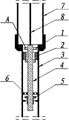
the main complete section structural representation of looking of the on-the-spot application of Fig. 1-the utility model;
the master of Fig. 2-baffle plate 6 looks complete section structural representation;
in figure, 1, joint, 2, oil-pumping plunger, 3, pump barrel, 4, sealed plunger, 5, circulation valve, 6, baffle plate, 7, oil pipe, 8, sucker rod; A. pressed on ring discharge orifice, circulation hole under B., C. centre bore.
The specific embodiment
by reference to the accompanying drawings, the utility model will be further described:
oil recovery circulation injection-recovery apparatus is comprised of joint 1, oil-pumping plunger 2, pump barrel 3, sealed plunger 4, circulation valve 5, baffle plate 6.Pump barrel 3 tops of its oil recovery circulation injection-recovery apparatus are provided with internal thread and are connected with tubing string 7, in pump barrel 3, be provided with sealed plunger 4, between sealed plunger 4 tops and pump barrel 3, be provided with oil-pumping plunger 2, the bottom of sealed plunger 4 is provided with circulation valve 5, circulation valve 5 tops are provided with baffle plate 6, and sealed plunger 4 tops are connected with sucker rod 8.
Claims (3)
1. an oil recovery circulation injection-recovery apparatus, comprising: joint (1), oil-pumping plunger (2), pump barrel (3), sealed plunger (4), circulation valve (5), baffle plate (6); It is characterized in that: pump barrel (3) top of described oil recovery circulation injection-recovery apparatus is provided with internal thread, in pump barrel (3), be provided with sealed plunger (4), between sealed plunger (4) top and pump barrel (3), be provided with oil-pumping plunger (2), the bottom of sealed plunger (4) is provided with circulation valve (5), and circulation valve (5) top is provided with baffle plate (6).
2. oil recovery circulation injection-recovery apparatus according to claim 1, is characterized in that: described sealed plunger (4) top is provided with pressed on ring discharge orifice (A).
3. oil recovery circulation injection-recovery apparatus according to claim 1, is characterized in that: described baffle plate (6) is provided with centre bore (C) and lower circulation hole (B).
Priority Applications (1)
| Application Number | Priority Date | Filing Date | Title |
|---|---|---|---|
| CN201320807360.3U CN203584382U (en) | 2013-12-07 | 2013-12-07 | Extract oil circulation injection and extraction device |
Applications Claiming Priority (1)
| Application Number | Priority Date | Filing Date | Title |
|---|---|---|---|
| CN201320807360.3U CN203584382U (en) | 2013-12-07 | 2013-12-07 | Extract oil circulation injection and extraction device |
Publications (1)
| Publication Number | Publication Date |
|---|---|
| CN203584382U true CN203584382U (en) | 2014-05-07 |
Family
ID=50582318
Family Applications (1)
| Application Number | Title | Priority Date | Filing Date |
|---|---|---|---|
| CN201320807360.3U Expired - Fee Related CN203584382U (en) | 2013-12-07 | 2013-12-07 | Extract oil circulation injection and extraction device |
Country Status (1)
| Country | Link |
|---|---|
| CN (1) | CN203584382U (en) |
Cited By (1)
| Publication number | Priority date | Publication date | Assignee | Title |
|---|---|---|---|---|
| CN107191163A (en) * | 2017-08-01 | 2017-09-22 | 克拉玛依市创铭石油科技有限公司 | Casing gas exhaust apparatus |
-
2013
- 2013-12-07 CN CN201320807360.3U patent/CN203584382U/en not_active Expired - Fee Related
Cited By (1)
| Publication number | Priority date | Publication date | Assignee | Title |
|---|---|---|---|---|
| CN107191163A (en) * | 2017-08-01 | 2017-09-22 | 克拉玛依市创铭石油科技有限公司 | Casing gas exhaust apparatus |
Similar Documents
| Publication | Publication Date | Title |
|---|---|---|
| CN102758602B (en) | Concentric tube hydraulic piston drainage and extraction device and method for coal-bed gas well | |
| CN104695884A (en) | Wellhead automatic capture device and process method for gas-lifting plunger | |
| CN203655585U (en) | Long plunger type injection-production pump | |
| CN203584382U (en) | Extract oil circulation injection and extraction device | |
| CN202810812U (en) | An oil extraction pipe column lifting thickened oil with steam power | |
| CN203098261U (en) | Sand-bury-preventing oil well pump oil inlet valve | |
| CN104612944A (en) | Viscous oil pump | |
| CN203742575U (en) | Dual-seal oil pumping device for steam injection and oil extraction | |
| CN204344428U (en) | A kind of thick oil pump | |
| CN204163964U (en) | Ring valve type hydraulic feedback oil | |
| CN203297087U (en) | Efficient protective oil pumping device | |
| CN203879719U (en) | Integrated gas injecting and oil extracting pump | |
| CN203394717U (en) | Tandem long plunger rod type oil-well pump of travelling valve | |
| CN204609843U (en) | Hydraulic drive type oil extraction system | |
| CN202745804U (en) | Outer channeling groove lugging device of oil-water well sleeve | |
| CN202560525U (en) | Variable displacement fracturing and swabbing combined pump | |
| CN203603862U (en) | Hydraulic feedback injection-production device | |
| CN104747139B (en) | Hydraulic drive type oil extraction system | |
| CN102691488B (en) | Anomalous character plastic cement injects packing_seal wellhead assembly and method | |
| CN202108480U (en) | Constant pressure gas discharge wellhead device of oil well sleeve | |
| CN203499988U (en) | Tubular pump fixed valve assembly | |
| CN203655262U (en) | Oil extraction gas injection device | |
| CN201425018Y (en) | Pipe column drainage pump for oil well | |
| CN103835688A (en) | Double-seal steam-injection and oil-extraction dual-purpose oil pumping device | |
| CN203499648U (en) | Novel oil well oil-extracting pipe column |
Legal Events
| Date | Code | Title | Description |
|---|---|---|---|
| C14 | Grant of patent or utility model | ||
| GR01 | Patent grant | ||
| CF01 | Termination of patent right due to non-payment of annual fee |
Granted publication date: 20140507 Termination date: 20141207 |
|
| EXPY | Termination of patent right or utility model |