Background technology
Along with the development of power electronic technology, the structural design of high-power converter (comprising wind electric converter, photovoltaic DC-to-AC converter) is more and more compacter, like this, causes heat more and more concentrated on the one hand, causes on the other hand heat radiation more difficult.Past solution is normally arranged on the heater element in current transformer (as IGBT, rectifier bridge) etc. on the radiator of copper (aluminium) system, and on cabinet (shell) body of this radiator, installs fan additional, and the air channel of matching design allows heat fall apart to outside.But along with the raising of power density, the increase of current transformer caloric value, the air-cooled requirement that can not meet heat radiation.In recent years, water-cooling technology has had development at full speed, and it has not only surpassed as radiating modes such as air-cooled, heat pipes on radiating effect, and in noise control, the aspects such as applied environment adaptability have also reached good effect.Therefore,, high-power, in the heat radiation of the power electronic product of high power density, water-cooling technology is used widely.
After adopting water-cooling, for the sealing IP grade of current transformer rack can be done more, simultaneously also in order to meet the instructions for use of various adverse circumstances, except the IGBT of high heat flux adopts the radiating mode of direct water-cooling (by liquid cooling heat radiator by the dissipation of heat of IGBT outside rack), other heater element of current transformer interior of equipment cabinet (comprises inductance, copper bar, contactor, circuit breaker, capacitance module, fuse etc.) common employing first transfers heat to the air of current transformer interior of equipment cabinet, air after being heated enters the gas-liquid heat exchanger in converter cabinet under the driving of blower fan, effect due to the temperature difference, the heat of air will pass to gas-liquid heat exchanger, the heat of gas-liquid heat exchanger will pass to the cooling fluid of gas-liquid heat exchanger further, mobile cooling fluid is taken this heat out of current transformer rack, enter in outside heat exchanger and (be generally air-cooled heat exchanger), finally by this outside heat exchanger, heat is delivered in atmosphere, thereby reach cooling object, as shown in Figure 1.
According to the first law of thermodynamics, heat can only be delivered to cryogenic object from high temp objects.In above-mentioned narrated heat transfer process, existence due to thermal resistance, the temperature of current transformer rack internal heat generation element must be greater than the air themperature in rack, and the air themperature in rack must be greater than the temperature of gas-liquid heat exchanger, and the temperature of gas-liquid heat exchanger must be greater than the temperature of cooling fluid; Same, the coolant temperature in current transformer rack must be greater than extraneous ambient temperature, could meet heat and from the heater element in cabinet, be delivered to the process of current transformer outside air.
Therefore, the air themperature in rack generally can be than high 10 degree~30 degree of ambient temperature, and regional area even can be higher.For example, when ambient temperature is 45 degree, it is even higher that the air themperature in rack will reach 70 degree.
As everyone knows, one of principal element that affects device useful life and reliability is its ambient temperature of using.Adopt the current transformer of water-cooling, in its cabinet, air themperature is high more a lot of than ambient temperature, in order to guarantee useful life and the reliability of device, generally need to use nonstandard resistant to elevated temperatures device to solve, and adopt the cost of nonstandard resistant to elevated temperatures device to be multiplied.If but do not use high temperature resistant device, will there are frequently various faults in current transformer, the periodic replacement of device and periodic maintenance cost will be higher.
Utility model content
The utility model is for the current transformer of existing use water-cooling, in its cabinet, air themperature is high more a lot of than ambient temperature, useful life and the reliability of components and parts in rack have been reduced, increased the manufacturing cost of current transformer and the problem of maintenance cost, a kind of cooling system of current transformer is provided.
The solution that the utility model provides with regard to its technical purpose is as follows:
The utility model provides a kind of current transformer cooling device, and for current transformer, described current transformer comprises function counter and power cabinet, and the side of described function counter and the side of described power cabinet fit together; Described function counter inside is formed with function counter accommodation space, is equipped with current transformer function components and parts in this function counter accommodation space;
Described current transformer cooling device comprises input duct and fluid pipeline; Described power cabinet inside is formed with power cabinet accommodation space, and described input duct and described fluid pipeline run through this power cabinet, and stretches in described power cabinet accommodation space; Described power cabinet accommodation space is provided with power model accommodation space and inductor accommodation space; In described power model accommodation space, be provided with power model, in described inductor accommodation space, be provided with inductor;
Described current transformer cooling device also comprises the liquid cooling heat radiator being arranged in described power model accommodation space for to described power model heat radiation, and this liquid cooling heat radiator has liquid cooling heat radiator inlet and liquid cooling heat radiator liquid outlet; Described power model is arranged on described liquid cooling heat radiator;
Described current transformer cooling device also comprise be arranged in described current transformer for giving the liquid cooling apparatus of described current transformer function components and parts and the heat radiation of described inductor, this liquid cooling apparatus comprises condenser, compressor and evaporator; Described condenser, described evaporator and described compressor connect into the first loop by pipeline; In this first loop, be provided with cold-producing medium; Described condenser has condenser inlet and condenser liquid outlet;
Described liquid cooling heat radiator inlet and described condenser inlet are communicated with described input duct respectively; Described liquid cooling heat radiator liquid outlet and described condenser liquid outlet respectively with described fluid pipeline communication;
Described current transformer inside is also provided with the blower fan for generation of circulating current.
In the above-mentioned current transformer cooling device of the utility model, described condenser and described compressor are arranged on the sidepiece of inductor described in described inductor accommodation space;
Described liquid cooling apparatus comprises a plurality of described evaporators, and the plurality of evaporator is separately positioned in described function counter accommodation space and described inductor accommodation space;
Described evaporator in described inductor accommodation space is arranged on top or the sidepiece of described inductor.
In the above-mentioned current transformer cooling device of the utility model, described current transformer function components and parts are arranged on the top of described function counter accommodation space;
Described evaporator in described function counter accommodation space is arranged on the bottom of described function counter accommodation space.
In the above-mentioned current transformer cooling device of the utility model, described power model comprises IGBT.
In the above-mentioned current transformer cooling device of the utility model, described current transformer function components and parts comprise contactor, circuit breaker, relay, transformer, capacitance module.
In the above-mentioned current transformer cooling device of the utility model, described current transformer cooling device also comprises external heat exchanger and the cooling fluid supply device that is arranged on described current transformer outside; Described external heat exchanger has external heat exchanger inlet and external heat exchanger liquid outlet, and described cooling fluid supply device has cooling fluid supply device inlet and cooling fluid supply device liquid outlet;
Described fluid pipeline is communicated with described external heat exchanger inlet, and described external heat exchanger liquid outlet is communicated with described cooling fluid supply device inlet, and described cooling fluid supply device liquid outlet is communicated with described input duct;
In described fluid pipeline, described input duct, described external heat exchanger, described cooling fluid supply device and the passage that is interconnected thereof, be provided with the first cooling fluid.
In the above-mentioned current transformer cooling device of the utility model, described liquid cooling apparatus also comprises pump, the first liquid cooling heat exchanger; This first liquid cooling heat exchanger has the first liquid cooling heat exchanger inlet and the first liquid cooling heat exchanger liquid outlet, and described evaporator has evaporator inlet and evaporator liquid outlet;
Described evaporator liquid outlet is communicated with the pump inlet of described pump, and the pump liquid outlet of described pump is communicated with described the first liquid cooling heat exchanger inlet, and described the first liquid cooling heat exchanger liquid outlet is communicated with described evaporator inlet, thereby forms the 3rd loop; In described the 3rd loop, be provided with the second cooling fluid.
In the above-mentioned current transformer cooling device of the utility model, described pump is arranged at the sidepiece of inductor described in described inductor accommodation space.
In the above-mentioned current transformer cooling device of the utility model, described liquid cooling apparatus comprises a plurality of described the first liquid cooling heat exchangers, and described a plurality of the first liquid cooling heat exchangers are separately positioned in described function counter accommodation space and described inductor accommodation space;
Described the first liquid cooling heat exchanger in described inductor accommodation space is arranged on top or the sidepiece of described inductor.
In the above-mentioned current transformer cooling device of the utility model, described liquid cooling apparatus also comprises the second liquid cooling heat exchanger; This second liquid cooling heat exchanger has the second liquid cooling heat exchanger inlet and the second liquid cooling heat exchanger liquid outlet, and described evaporator has evaporator inlet and evaporator liquid outlet;
Described evaporator inlet is communicated with described input duct, and described evaporator liquid outlet is communicated with described the second liquid cooling heat exchanger inlet, described the second liquid cooling heat exchanger liquid outlet and described fluid pipeline communication.
In the above-mentioned current transformer cooling device of the utility model, described assembling is on described the first liquid cooling heat exchanger or described the second liquid cooling heat exchanger.
In the above-mentioned current transformer cooling device of the utility model, described assembling is on described evaporator.
In the above-mentioned current transformer cooling device of the utility model, described power cabinet accommodation space and described function counter accommodation space be airtight or mutual conduction respectively.
The utility model, by liquid cooling apparatus being set in current transformer inside, has reduced the air themperature in current transformer rack widely, thereby has improved useful life and the reliability of components and parts in rack; On the other hand, liquid cooling apparatus of the present invention and liquid cooling heat radiator share feed liquor and fluid pipeline, its pipeline structure compact in design, simple and practical, and cost is lower.
Embodiment
The first embodiment
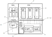
Referring to Fig. 2, Fig. 3 and Figure 10, Fig. 2, Fig. 3 and Figure 10 show the current transformer cooling device of the utility model the first embodiment.
With reference to Fig. 2 and Fig. 3, this current transformer cooling device, for current transformer, current transformer comprises function counter 51 and power cabinet 52, the side of the side of function counter 51 and power cabinet 52 fits together; Function counter 51 inside are formed with airtight function counter accommodation space, are equipped with current transformer function components and parts in this function counter accommodation space;
In the present embodiment, current transformer function components and parts comprise contactor, circuit breaker, relay, transformer, capacitance module.
Further, referring to Fig. 2, current transformer cooling device comprises input duct 401 and fluid pipeline 402; Power cabinet 52 inside are formed with airtight power cabinet accommodation space, and input duct 401 and fluid pipeline 402 run through this power cabinet 52, and stretch in power cabinet accommodation space; Power cabinet accommodation space is divided into the power model accommodation space on top and the inductor accommodation space of bottom, and input duct 401 and fluid pipeline 402 are arranged between power model accommodation space and inductor accommodation space; In power model accommodation space, be provided with power model 201, in inductor accommodation space, be provided with inductor 54; In the present embodiment, this inductor 54 is vertical putting.
Usually, power model comprises IGBT(insulated gate bipolar transistor).
Further, in the present embodiment, referring to Fig. 2 and Fig. 3, current transformer cooling device also comprises the liquid cooling heat radiator 203 being arranged in power model accommodation space for to power model 201 heat radiations, and this liquid cooling heat radiator 203 has liquid cooling heat radiator inlet and liquid cooling heat radiator liquid outlet; Power model 201 is arranged on liquid cooling heat radiator 203.Liquid cooling heat radiator 201 is generally become by metal guide hot body or other nonmetallic heat conductive system, the heat distributing during power model 201 work, by heat, conducted and passed to the liquid cooling heat radiator 201 of being made by heat carrier, the heat on liquid cooling heat radiator 201 is taken away by the cooling fluid in this liquid cooling heat radiator 201.
Particularly, in the present embodiment, referring to Figure 10, liquid cooling heat radiator inlet is communicated with input duct 401; Liquid cooling heat radiator liquid outlet is communicated with fluid pipeline 402;
Current transformer cooling device also comprises external heat exchanger 30 and the cooling fluid supply device 40 that is arranged on current transformer outside; External heat exchanger 30 has external heat exchanger inlet and external heat exchanger liquid outlet, and cooling fluid supply device 40 has cooling fluid supply device inlet and cooling fluid supply device liquid outlet;
Fluid pipeline 402 is communicated with external heat exchanger inlet, and external heat exchanger liquid outlet is communicated with cooling fluid supply device inlet, and cooling fluid supply device liquid outlet is communicated with input duct 401;
Like this, liquid cooling heat radiator 203, fluid pipeline 402, input duct 401, external heat exchanger 30, cooling fluid supply device 40 and the passage that is interconnected thereof form the second loop;
Cooling fluid supply device 40 is for inputting the first cooling fluid to input duct 401.This first cooling fluid can circulate in the second loop.
In the present embodiment, the first cooling fluid can be any one in water, ethylene glycol, propylene glycol, or both (for example glycol water, aqueous solution of propylene glycol) such as mixed liquors wherein.In the present embodiment, this first cooling fluid is the mixed liquor of water, ethylene glycol.
The heat radiation process of 203 pairs of power models 201 of liquid cooling heat radiator is as follows: power model 201 evolution of heat when work, this heat is conducted and is passed to the liquid cooling heat radiator 203 of being made by heat carrier by heat, the first cooling fluid in this liquid cooling heat radiator 203 obtains the heat on this liquid cooling heat radiator 203 by carrying out heat exchange with this liquid cooling heat radiator 203, then this first cooling fluid is taken heat out of current transformer, again by external heat exchanger 30 by dissipation of heat in the air of current transformer outside, finally come back in cooling fluid supply device 40, thereby realized recycling of the first cooling fluid.
Certainly can understand, external heat exchanger 30 is not necessary device, and the air of current transformer inside transfers heat to after the first cooling fluid, and this first cooling fluid can directly be discharged by fluid pipeline 402, or enters other system (as steam generator system).
In the present embodiment, current transformer cooling device also comprise be arranged in current transformer for giving the liquid cooling apparatus 10 of current transformer function components and parts and inductor 54 heat radiations, this liquid cooling apparatus 10 comprises condenser 103, compressor 102 and evaporator 101; Condenser 103, evaporator 101 and compressor 102 connect into the first loop by pipeline, and this pipeline comprises the pipeline assemblies such as expansion valve; In this first loop, be provided with cold-producing medium; Condenser 103 has condenser inlet and condenser liquid outlet;
Condenser inlet is communicated with input duct 401; Condenser liquid outlet is communicated with fluid pipeline 402; Like this, cooling fluid supply device 40 can flow in fluid pipeline 402 through condenser 103 to the first cooling fluid of input in input duct 401, thereby flows out current transformer.
The heat radiation process of liquid cooling apparatus 10 is as follows: the dissipation of heat that the current transformer function components and parts of current transformer inside and inductor 54 are sent is to the air of current transformer inside, evaporator 101 is the entrained heat absorption of the air of current transformer inside, and by this heat, the cold-producing medium in evaporator evaporated; The cold-producing medium of this evaporation enters condenser 103 under the effect of compressor 102, and carry out heat exchange with same the first cooling fluid in this condenser 103 in this condenser 103, thereby the entrained heat of cold-producing medium is passed to the first cooling fluid, and take current transformer out of by the first cooling fluid.
In the present embodiment, condenser 103 and compressor 102 are arranged on the sidepiece of inductor 54 in inductor accommodation space;
In the present embodiment, liquid cooling apparatus 10 comprises a plurality of evaporators 101, and the plurality of evaporator 101 is separately positioned in function counter accommodation space and inductor accommodation space; Further, in the present embodiment, the evaporator 101 in inductor accommodation space is arranged on the top of inductor 54;
In the present embodiment, current transformer function components and parts are arranged on the top of function counter accommodation space; Evaporator 101 in function counter accommodation space is arranged on the bottom of function counter accommodation space.
Power cabinet accommodation space and function counter accommodation space are respectively arranged with the blower fan 202 for generation of circulating current.
Particularly, in the present embodiment, on each evaporator 101, blower fan 202 is all installed; Under the effect of Coanda effect, the blower fan 202 in function counter accommodation space can be created in the air-flow circulating in this function counter accommodation space, thereby accelerates the flowing velocity of the air in function counter accommodation space.Similarly, the blower fan 202 in inductor accommodation space can be created in the air-flow circulating in this power cabinet accommodation space, thereby accelerates the flowing velocity of the air in power cabinet accommodation space.
The second embodiment
With reference to Fig. 4, Fig. 5 and Figure 10, the difference of the second embodiment and the first embodiment is evaporator 101 in inductor 54 and inductor accommodation space and the setting position of blower fan 202.
In the present embodiment, inductor 54 is horizontal putting.
Evaporator 101 in inductor accommodation space is arranged on the sidepiece (between inductor 54 and current transformer Rear Door) of this inductor 54.Similarly, be installed on the sidepiece that blower fan 202 on the evaporator 101 in this inductor accommodation space is also arranged on this inductor 54.And this setup makes current transformer inner member layout obtain compacter.
The 3rd embodiment
With reference to Fig. 6, Fig. 7 and Figure 11, the difference of the 3rd embodiment and the first embodiment is: liquid cooling apparatus 10 also comprises pump 104, the first liquid cooling heat exchanger 106; And evaporator 101 is only arranged in power cabinet accommodation space; Blower fan 202 is installed on the first liquid cooling heat exchanger 106.
This first liquid cooling heat exchanger 106 has the first liquid cooling heat exchanger inlet and the first liquid cooling heat exchanger liquid outlet, and evaporator 101 has evaporator inlet and evaporator liquid outlet;
Evaporator liquid outlet is communicated with the pump inlet of pump 104, and the pump liquid outlet of pump 104 is communicated with the first liquid cooling heat exchanger inlet, and the first liquid cooling heat exchanger liquid outlet is communicated with evaporator inlet, thereby forms the 3rd loop; In the 3rd loop, be provided with the second cooling fluid.
In the present embodiment, the second cooling fluid can be any one in water, ethylene glycol, propylene glycol, or both (for example glycol water, aqueous solution of propylene glycol) such as mixed liquors wherein.In the present embodiment, this second cooling fluid is the mixed liquor of water, ethylene glycol.
Wherein, the power of pump 104 for providing this second cooling fluid to circulate at the 3rd loop.The second cooling fluid is under the driving of this pump 104, by the first liquid cooling heat exchanger inlet, enter in the first liquid cooling heat exchanger 106, carry out heat exchange with the air of current transformer inside, absorb the entrained heat of air of current transformer inside, then from the first liquid cooling heat exchanger liquid outlet, flow out, by evaporator inlet, enter evaporator 101 again, and carry out heat exchange with same cold-producing medium in this evaporator 101 in evaporator 101, thereby the entrained heat of this second cooling fluid is passed to cold-producing medium; Finally, by the cold-producing medium that carries out and the heat exchange between the first cooling fluid, the heat of current transformer inner air is delivered to current transformer outside in condenser 103.
In the present embodiment, pump 104 is arranged at the sidepiece of inductor 54 in inductor accommodation space.
In the present embodiment, liquid cooling apparatus 10 comprises a plurality of the first liquid cooling heat exchangers 106, and a plurality of the first liquid cooling heat exchangers 106 are separately positioned in function counter accommodation space and inductor accommodation space.
The first liquid cooling heat exchanger 106 in inductor accommodation space is arranged on the top of inductor 54.
On each first liquid cooling heat exchanger 106, blower fan 202 is all installed; Under the effect of Coanda effect, the blower fan 202 in function counter accommodation space can be created in the air-flow circulating in this function counter accommodation space, thereby accelerates the flowing velocity of the air in function counter accommodation space.Similarly, the blower fan 202 in inductor accommodation space can be created in the air-flow circulating in this power cabinet accommodation space, thereby accelerates the flowing velocity of the air in power cabinet accommodation space.
The 4th embodiment
With reference to Fig. 8, Fig. 9 and Figure 11, the difference of the 4th embodiment and the 3rd embodiment is the first liquid cooling heat exchanger 106 in inductor 54 and inductor accommodation space and the setting position of blower fan 202.
In the present embodiment, inductor 54 is horizontal putting.
The first liquid cooling heat exchanger 106 in inductor accommodation space is arranged on the sidepiece (being between inductor 54 and Rear Door) of this inductor 54.Similarly, be installed on the sidepiece that blower fan 202 on the first liquid cooling heat exchanger 106 in this inductor accommodation space is also arranged on this inductor 54.And this setup makes current transformer inner member layout obtain compacter.
The 5th embodiment
With reference to Figure 12, Figure 13 and Figure 14, the difference of the 5th embodiment and the first embodiment is: liquid cooling apparatus 10 also comprises the second liquid cooling heat exchanger 105, and evaporator 101 is only arranged in power cabinet accommodation space; Blower fan 202 is installed on the second liquid cooling heat exchanger 105.
In the present embodiment, with reference to Figure 14, liquid cooling apparatus 10 also comprises the second liquid cooling heat exchanger 105, and this second liquid cooling heat exchanger 105 has the second liquid cooling heat exchanger inlet and the second liquid cooling heat exchanger liquid outlet, and evaporator 101 has evaporator inlet and evaporator liquid outlet;
Evaporator inlet is communicated with input duct 401, and evaporator liquid outlet is communicated with the second liquid cooling heat exchanger inlet, and the second liquid cooling heat exchanger liquid outlet is communicated with fluid pipeline 402.Like this, the first cooling fluid can flow out current transformer by evaporator 101 and the second liquid cooling heat exchanger 105 successively.
Wherein, the first cooling fluid enters evaporator 101 from evaporator inlet, by evaporator 101, absorbed heat and lower the temperature, then from evaporator liquid outlet, flow out, enter the second liquid cooling heat exchanger 105, carry out heat exchange with the air of current transformer inside, thereby absorb the airborne heat of current transformer, then flow out current transformer.
In order to make air and the heat exchange between the first cooling fluid of current transformer inside more efficient, the second liquid cooling heat exchanger 105 can arrange a plurality of.The plurality of the second liquid cooling heat exchanger 105 is separately positioned in function counter accommodation space and inductor accommodation space.
On each second liquid cooling heat exchanger 105, blower fan 202 is all installed; Under the effect of Coanda effect, the blower fan 202 in function counter accommodation space can be created in the air-flow circulating in this function counter accommodation space, thereby accelerates the flowing velocity of the air in function counter accommodation space.Similarly, the blower fan 202 in inductor accommodation space can be created in the air-flow circulating in this power cabinet accommodation space, thereby accelerates the flowing velocity of the air in power cabinet accommodation space.
The 6th embodiment
With reference to Figure 15 and Figure 16, the difference of the 6th embodiment and above-mentioned any embodiment is that function counter 51 and power cabinet 52 are mutual conduction, and blower fan 202 only produces an airflow circulating in current transformer.
Particularly, with reference to Figure 15, in Koln, reach under the effect of effect, the inwall that the air-flow being produced by blower fan 202 can paste function counter accommodation space and power cabinet accommodation space flows, thereby form an airflow circulating, accelerate the heat exchange between evaporator 101 and current transformer inner air.
Should be understood that, for those of ordinary skills, can be improved according to the above description or convert, and all these improvement and conversion all should belong to the protection range of the utility model claims.