CN203522590U - Mining traction electric locomotive chopping speed regulator - Google Patents
Mining traction electric locomotive chopping speed regulator Download PDFInfo
- Publication number
- CN203522590U CN203522590U CN201320607906.0U CN201320607906U CN203522590U CN 203522590 U CN203522590 U CN 203522590U CN 201320607906 U CN201320607906 U CN 201320607906U CN 203522590 U CN203522590 U CN 203522590U
- Authority
- CN
- China
- Prior art keywords
- igbt
- speed regulator
- direct current
- power supply
- snubber circuit
- Prior art date
- Legal status (The legal status is an assumption and is not a legal conclusion. Google has not performed a legal analysis and makes no representation as to the accuracy of the status listed.)
- Expired - Fee Related
Links
Images


Abstract
The utility model discloses a mining traction electric locomotive chopping speed regulator. The speed regulator comprises a power supply, a direct current motor, an IGBT, an absorption capacitor, a change-over switch and a buffer absorbing circuit module. The buffer absorbing circuit module comprises several buffer absorbing circuits which are connected in parallel. A drain electrode of the IGBT is connected with a positive electrode of the power supply through a diode. A source electrode of the IGBT is connected with a negative electrode E- of the power supply. A drain electrode end of the IGBT passes through a coil of the direct current motor and then is connected in series with connection of the change-over switch and the direct current motor. The buffer circuit module is connected between the drain electrode and the source electrode of the IGBT. The absorption capacitor C1 is connected between the positive electrode and the negative electrode of the power supply. The direct current motor is connected with the power supply through the change-over switch. During reverse braking, a main power tube IGBT is easy to be damaged. Aiming at the above problem, according to the speed regulator of the utility model, the buffer absorbing circuit is added so that an undesirable spike pulse is effectively restrained, a peak value voltage maintains to be in a normal value scope and a service life of a device is prolonged. Cost is low and installation is simple.
Description
Technical field
The utility model relates to a kind of chopper speed regulator, particularly a kind of mining traction electric motor chopper speed regulator.
Background technology
Chopper speed regulator is since emerging, and its advance is self-evident.Current chopper speed regulator adopts IGBT(igbt more) as main power device, so that it is simple in structure, easy to maintenance, speed governing is steady, energy-conservation 30% outstanding representation, replace the great rheostatic speed regulation mode of power consumption and maintenance capacity (being called for short rheostatic speed regulation device), become the main product of mining traction electric motor driver operation platform.
But in initial use procedure, the real work of IGBT does not really reach the useful life of desired design useful life, be mainly manifested in IGBT and be very easy to damage.Through Practice Survey, find, when frequent use plugging, the spoilage of IGBT is the highest.Plugging be mining traction electric motor in use, one of Main Means that slows down, brakes and brake, be characterized in highly sensitive, response speed is fast, reliability is strong, another kind is that hand-operated wheel type slows down, skidding, but retro-speed is slow, can not meet driver's demand in actual use.
Utility model content
The purpose of this utility model is to provide a kind of reliable mining traction electric motor chopper speed regulator of long service life.
This mining traction electric motor chopper speed regulator that the utility model provides, comprises power supply, direct current machine, IGBT, Absorption Capacitance, reversing switch and snubber circuit module, and this snubber circuit module comprises some snubber circuits that are connected in parallel; The drain electrode of IGBT is connected with the positive pole of power supply by diode, and the source electrode of this IGBT is connected with power cathode E-, and the drain electrode end of this IGBT is connected being connected of reversing switch and direct current machine by the coil of direct current machine again; Buffer circuit module is connected between the drain electrode and source electrode of IGBT; Absorption Capacitance C1 is connected between positive source and negative pole; Direct current machine is connected with power supply by reversing switch.
Described snubber circuit module comprises 8 groups of snubber circuit unit that are connected in parallel, and every group of snubber circuit unit comprises the snubber circuit that 2 tunnels are connected in parallel.Described snubber circuit comprises resistive module, electric capacity and diode, and after resistive module and diodes in parallel, series capacitance is connected in series again; One end of resistive module and diodes in parallel is connected with the drain electrode of described IGBT, and electric capacity one end is connected with the source electrode of described IGBT.Described resistive module comprises 8 Chip-Rs, after 4 Chip-Rs are one another in series, is connected in parallel with other 4 Chip-Rs that have been connected in series.
The utility model during for plugging main power tube IGBT easily damage and increase snubber circuit, effectively suppressed bad spike, crest voltage is remained in range of normal value, improved the useful life of device.The utility model cost is very low, is to adopt 1/3 of independent component cost, installs simply, and volume is little, without changing existing anti-explosion box body.
Accompanying drawing explanation
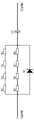
Fig. 1 is circuit theory schematic diagram of the present utility model.
Fig. 2 is that IGBT is voltage turn-offing and opening
u cEand electric current
i coscillogram.
Fig. 3 is RCD circuit theory diagrams.
Fig. 4 is RLCD circuit theory diagrams.
Fig. 5 is snubber circuit schematic diagram of the present utility model.
Embodiment
Chopper speed regulator is since emerging, and its advance is self-evident, and still, in initial use procedure, real work does not really reach the useful life of desired design useful life, is mainly manifested in IGBT and is very easy to damage.Through Practice Survey, find, when frequent use plugging, the spoilage of IGBT is the highest.
Plugging be mining traction electric motor in use, slow down, one of Main Means of brake and braking, be characterized in highly sensitive, response speed is fast, reliability is strong.
As long as do not damage the problem of IGBT while solving plugging, just can make product reach the useful life of desired design thus.As shown in Figure 1, during snubber circuit in not increasing dotted line frame, this of the detection that A is ordered crest voltage and peak current are higher than normal crest voltage and the electric current requiring.Principle Analysis according to IGBT, IGBT does not design snubber circuit (Fig. 1 dotted line frame: snubber circuit) be the basic reason that causes IGBT to damage, solution is at the A of IGBT point and 2 (being on switching tube QV) access snubber circuits of IGBT binding post, and crest voltage is remained in range of normal value.
In the existing chopper speed regulator that does not increase snubber circuit, its absorption capacitor C1 is the protection component of IGBT, is to be connected in parallel between the binding post 1 and 2 of IGBT, between the anodal E+ and negative pole E-of power supply.And the IGBT use of connecting with direct current machine in actual use, so IGBT is main switch, according to the using priciple of IGBT, absorption capacitor C1 does not have protective effect to IGBT.
Because the operating frequency of IGBT can be up to 30 ~ 50kHz; Therefore very little circuit inductance just may cause quite large current spike, thereby produces overvoltage, the safety that jeopardizes IGBT.From Fig. 2 (a), at electric current
i cin decline process, on IGBT, occurred overvoltage, its value is supply voltage
u cCwith inductive drop Ld
i c/ d
tboth stacks.
As shown in Fig. 2 (b), in figure, increase the electric current being exceedingly fast
i cthere is overcurrent spike
i cP, when this overcurrent spike
i cPwhile falling back to stationary value, excessive electric current rate of descent can cause equally and on IGBT, occurs overvoltage.When opening, IGBT there is peak current, its reason is due to the reverse recovery current of antiparallel fly-wheel diode on complementary pipe that superposeed on the IGBT load current in just conducting in brachium pontis, so before this diode recovery blocking-up, the IGBT of just conducting is upper form inverter bridge leg instantaneously run through short circuit, make electric current
i cthere is spike, need to seal in parallel connection buffer absorbing circuit for this reason.
For this shortcoming; the snubber circuit being formed by RCD network in parallel between the binding post 3 and 2 of IGBT; the functioning side of this snubber circuit overweights superpotential absorption and inhibition in switching process; thereby effectively suppressed bad spike; protect IGBT, reached the useful life of product desired design.
As shown in Figure 1, the utility model comprises power supply, direct current machine, IGBT, sustained diode 1, Absorption Capacitance, reversing switch K1, reversing switch K2, reversing switch K3, reversing switch K4 and snubber circuit module.The drain electrode of IGBT is connected with the anode tap of sustained diode 1, and the cathode terminal of this sustained diode 1 is connected with positive source E+, and the source electrode of this IGBT is connected with power cathode E-.Buffer circuit module is connected between the drain electrode and source electrode of IGBT.Absorption Capacitance C1 is connected between the cathode terminal of sustained diode 1 and the source terminal of IGBT.The drain electrode end of this IGBT is connected by connect the again M4 end of reversing switch K3 and direct current machine of the coil of direct current machine.The M3 end of direct current machine is connected with power supply E+ by reversing switch K1.Power supply E+ is connected with the M4 end of direct current machine by reversing switch K2, and power supply E-is connected with the M3 end of direct current machine by reversing switch K4.Wherein, reversing switch K1 and reversing switch K3 are normally closed switch, and reversing switch K2 and reversing switch K4 are normal open switch.Snubber circuit shown in Fig. 1 is equivalent electric circuit of the present utility model, and it comprises resistive module Rs, capacitance module Cs and diode (led) module Ds.
Circuit theory: when IGBT turn-offs, direct current machine relies on inertia in free running, now direct current machine is equivalent to generator in work, at A point, has electromotive force to exist, and this electromotive force feeds back to positive source E+ by sustained diode 1 and holds, if while not waiting rotating speed of direct current machine to reduce to zero, just operate reversing handle, motor is carried out to plugging, reversing switch K1 and reversing switch K3 all turn-off, reversing switch K2 and reversing switch K4 are all open-minded, so easily cause the damage of IGBT.This is that the overvoltage and the overcurrent peak value that produce during due to plugging are very high, the reverse recovery current of antiparallel sustained diode 2 on complementary pipe has superposeed in brachium pontis on the IGBT load current of just conducting, so before this diode recovery blocking-up, the IGBT of just conducting is upper form inverter bridge leg instantaneously run through short circuit, make electric current
i cthere is spike, cause IGBT to damage.Need between the binding post 3 and 2 of IGBT, access RCD snubber circuit for this reason.Because capacitor C s voltage can transition, limited and heavily added electric current/due to voltage spikes.Energy when IGBT opens on capacitor C s is released through Rs, effectively suppresses and has absorbed harmful spike.
In general application, what RCD snubber circuit adopted is independently resistance R s, capacitor C s and the use of diode Ds component units, and the circuit connecting mode of this circuit as shown in Figure 3 and Figure 4.As shown in Figure 3, when the overcurrent of circuit is in milliampere-ampere level, and the operating current of chopper speed regulator own is when hundred amperes of levels, because of the IGBT use of connecting with direct current machine, overvoltage and overcurrent that switching characteristic while considering IGBT work and direct current machine produce in the course of the work, both stacks consider known, and the overcurrent capability of snubber circuit can not be less than the operating current of chopper speed regulator own.So, selected electric capacity and diode and resistance all will be used high power device, and to install radiator additional, this way causes that product design costs is high, product own vol is large, is subject to the restriction of chopper speed regulator inner space in addition, will change anti-explosion box body, so, will again do product certification, the cycle is very long, has a strong impact on the economic benefit of enterprise.Therefore, the utility model adopts the technical scheme of small-power RCD unit parallel connection, has effectively solved the problems referred to above, and cost is very low, and volume is little, installs simply, is to adopt 1/3 of independent component cost, does not need to change former casing.
As shown in Figure 4, the inductance L s connecting with IGBT is for suppressing the excessive of current/voltage spike, and the capacitor C s in parallel with it charges by fast diode Ds, absorbs the overvoltage energy occurring on device, because capacitance voltage can transition, limited and heavily added electric current/due to voltage spikes.Energy when IGBT opens on capacitor C s is released through resistance R s.In order to reduce loss, the form that can be Fig. 3 by the RLCD circuit reduction in Fig. 4.This snubber circuit by RCD cell formation is principle foundation of the present utility model.
Snubber circuit module of the present utility model comprises some snubber circuits that are connected in parallel.In conjunction with concrete actual many factors, the utility model has carried out adaptive improvement to circuit as shown in Figure 4.
As shown in Figure 5, the snubber circuit that the utility model adopts comprises resistive module, capacitor C 1 and diode D1, after resistive module is in parallel with diode D1, is connected in series with capacitor C 1 again.Resistive module comprises 8 Chip-Rs, and these 8 Chip-Rs are divided into 2 groups, and 4 Chip-Rs in every group are one another in series and join, and these 2 groups of Chip-Rs that connected are connected in parallel afterwards again, form a kind of resistive module of the present utility model.
Being connected in parallel in the specific implementation, then by several above-mentioned snubber circuits.Because the voltage range of application scenario direct current machine is from tens volts to hundreds of volt, so the utility model preferably adopts 16 identical above-mentioned snubber circuits of parameter to be connected in parallel to each other to join, realize final snubber circuit module of the present utility model.For the ease of the making of pcb board and the heat radiation of device etc., the utility model is divided into 8 unit by these 16 snubber circuits that are connected in parallel, and each unit comprises the 2 above-mentioned snubber circuits in tunnel; The form layout that these 8 unit are listed as according to 4 row 2 is on pcb board, and the diode side of each unit configures a module radiator.The 2 above-mentioned snubber circuits in tunnel of each unit are connected in parallel, and on pcb board, the snubber circuit of 8 unit are connected in parallel afterwards.
Facts have proved, the utility model is practical, and has reached expection object.
Claims (4)
1. a mining traction electric motor chopper speed regulator, comprise power supply, direct current machine, IGBT, Absorption Capacitance, reversing switch, it is characterized in that, this speed regulator also comprises snubber circuit module, and this snubber circuit module comprises some snubber circuits that are connected in parallel; The drain electrode of IGBT is connected with the positive pole of power supply by diode, and the source electrode of this IGBT is connected with power cathode, and the drain electrode of this IGBT is connected after reversing switch again and is connected with the terminals of this direct current machine by the coil of direct current machine; Snubber circuit module is connected between the drain electrode and source electrode of IGBT; Absorption Capacitance is connected between positive source and negative pole; Direct current machine is connected with power supply by reversing switch.
2. mining traction electric motor chopper speed regulator according to claim 1, it is characterized in that, described snubber circuit module comprises 8 groups of snubber circuit unit that are connected in parallel, and every group of snubber circuit unit comprises the snubber circuit that 2 tunnels are connected in parallel.
3. mining traction electric motor chopper speed regulator according to claim 2, is characterized in that, described snubber circuit comprises resistive module, electric capacity and diode, after resistive module and diodes in parallel, joins with capacitances in series again; One end of resistive module and diodes in parallel is connected with the drain electrode of described IGBT, and electric capacity one end is connected with the source electrode of described IGBT.
4. mining traction electric motor chopper speed regulator according to claim 3, is characterized in that, described resistive module comprises 8 Chip-Rs, after 4 Chip-Rs are one another in series, is connected in parallel with other 4 Chip-Rs that have been connected in series.
Priority Applications (1)
| Application Number | Priority Date | Filing Date | Title |
|---|---|---|---|
| CN201320607906.0U CN203522590U (en) | 2013-09-30 | 2013-09-30 | Mining traction electric locomotive chopping speed regulator |
Applications Claiming Priority (1)
| Application Number | Priority Date | Filing Date | Title |
|---|---|---|---|
| CN201320607906.0U CN203522590U (en) | 2013-09-30 | 2013-09-30 | Mining traction electric locomotive chopping speed regulator |
Publications (1)
| Publication Number | Publication Date |
|---|---|
| CN203522590U true CN203522590U (en) | 2014-04-02 |
Family
ID=50381461
Family Applications (1)
| Application Number | Title | Priority Date | Filing Date |
|---|---|---|---|
| CN201320607906.0U Expired - Fee Related CN203522590U (en) | 2013-09-30 | 2013-09-30 | Mining traction electric locomotive chopping speed regulator |
Country Status (1)
| Country | Link |
|---|---|
| CN (1) | CN203522590U (en) |
Cited By (3)
| Publication number | Priority date | Publication date | Assignee | Title |
|---|---|---|---|---|
| CN108900133A (en) * | 2018-08-01 | 2018-11-27 | 浙江东方机电有限公司 | The permanent magnet synchronous motor control device and method of height driving conversion speed |
| CN112187032A (en) * | 2019-07-04 | 2021-01-05 | 台达电子工业股份有限公司 | Power supply device and operation method thereof |
| CN112260525A (en) * | 2020-10-10 | 2021-01-22 | 上海金脉电子科技有限公司 | IGBT (insulated Gate Bipolar transistor) driving topological circuit and soft switching circuit thereof |
-
2013
- 2013-09-30 CN CN201320607906.0U patent/CN203522590U/en not_active Expired - Fee Related
Cited By (5)
| Publication number | Priority date | Publication date | Assignee | Title |
|---|---|---|---|---|
| CN108900133A (en) * | 2018-08-01 | 2018-11-27 | 浙江东方机电有限公司 | The permanent magnet synchronous motor control device and method of height driving conversion speed |
| CN108900133B (en) * | 2018-08-01 | 2020-10-30 | 浙江东方机电有限公司 | Permanent magnet synchronous motor control device and method with high driving conversion speed |
| CN112187032A (en) * | 2019-07-04 | 2021-01-05 | 台达电子工业股份有限公司 | Power supply device and operation method thereof |
| CN112187032B (en) * | 2019-07-04 | 2022-03-15 | 台达电子工业股份有限公司 | Power supply device and operation method thereof |
| CN112260525A (en) * | 2020-10-10 | 2021-01-22 | 上海金脉电子科技有限公司 | IGBT (insulated Gate Bipolar transistor) driving topological circuit and soft switching circuit thereof |
Similar Documents
| Publication | Publication Date | Title |
|---|---|---|
| CN102427262B (en) | Elevator braking energy feedback and control system based on super capacitor | |
| CN101931366B (en) | Super capacitor-based energy-saving drive circuit of motor and control method | |
| CN103036238B (en) | Control structure and method of chain-type active power filter (FAPF) linkage unit bypass | |
| CN201252488Y (en) | High-power traction convertor | |
| CN102522882B (en) | Protection circuit of converter power component | |
| CN104578865A (en) | Tri-level four-leg T-shaped fault-tolerant converter and control method thereof | |
| CN104340085A (en) | Urban rail medium voltage energy feedback power supply method and device with ring current eliminating function | |
| CN204231188U (en) | Power conversion circuit and transducer air conditioning | |
| CN103066809A (en) | Improved residual current device (RCD) buffer circuit applied to direct tandem type insulated gate bipolar translator (IGBT) | |
| CN203522590U (en) | Mining traction electric locomotive chopping speed regulator | |
| CN105539164A (en) | Double-source electric locomotive converter | |
| CN101291104B (en) | Protecting method for sudden drop of electric and electronic equipment with medium or high electric power | |
| CN104767368A (en) | High-reliable tri-level inverter circuit current-limiting control method | |
| CN204172712U (en) | A kind of city rail medium-pressure type with circulation elimination function can present electric supply installation | |
| CN202772560U (en) | IGBT current foldback circuit and inductive load control circuit | |
| CN112152270A (en) | Superconducting magnetic energy storage device applied to subway train regenerative braking and control method thereof | |
| CN103625299A (en) | Double-source electric trolley bus control system | |
| CN204068408U (en) | Be applied to the novel power taking supply unit of cable work well array water | |
| CN112953235A (en) | High-power isolated multi-module parallel charging power supply for super-capacitor bus | |
| CN203119770U (en) | Multi-motor-driving frequency-converting and energy-saving device based on common DC bus and pumping unit | |
| CN106655819B (en) | Protector for short-circuit current rectifier of bidirectional converter | |
| CN103568851B (en) | The regenerative braking energy absorption device of rail vehicle and rail vehicle | |
| CN204720986U (en) | The compound circuit of a kind of integrated rectification, active power filtering and energy back braking function | |
| CN103532365A (en) | Brake unit | |
| CN209730881U (en) | Regenerate the super appearance energy storage device of energy |
Legal Events
| Date | Code | Title | Description |
|---|---|---|---|
| C14 | Grant of patent or utility model | ||
| GR01 | Patent grant | ||
| CF01 | Termination of patent right due to non-payment of annual fee |
Granted publication date: 20140402 Termination date: 20160930 |
|
| CF01 | Termination of patent right due to non-payment of annual fee |