CN203478344U - Multi-return-stroke reverse combustion heating furnace - Google Patents
Multi-return-stroke reverse combustion heating furnace Download PDFInfo
- Publication number
- CN203478344U CN203478344U CN201320557381.4U CN201320557381U CN203478344U CN 203478344 U CN203478344 U CN 203478344U CN 201320557381 U CN201320557381 U CN 201320557381U CN 203478344 U CN203478344 U CN 203478344U
- Authority
- CN
- China
- Prior art keywords
- chamber
- deashing
- return
- chimney
- hearth
- Prior art date
- Legal status (The legal status is an assumption and is not a legal conclusion. Google has not performed a legal analysis and makes no representation as to the accuracy of the status listed.)
- Expired - Fee Related
Links
Images


Abstract
The utility model relates to a multi-return-stroke reverse combustion heating furnace which comprises a furnace shell, a chimney, a water return pipe and a water outlet pipe. A furnace door, a hearth, a fire grate and a slag storage cavity are sequentially arranged in the furnace shell from top to bottom, and a hearth water jacket is arranged between the furnace shell and the hearth. The multi-return-stroke reverse combustion heating furnace is characterized in that an air opening communicated with the hearth is formed in the furnace shell, a return-stroke heating water jacket communicated with the hearth water jacket is arranged on the rear side of the hearth, an ash storage cavity is arranged at the bottom of the return-stroke heating water jacket, a first ash removing cavity and a second ash removing cavity are arranged on the top of the return-stroke heating water jacket, a plurality rows of parallel return-stroke flue pipes are arranged among the slag storage cavity, the ash storage cavity, the first ash removing cavity and the second ash removing cavity, the chimney with a draft fan is communicated with the second ash removing cavity or the return-stroke flue pipes, and the return-stroke flue pipes guide flue gas to sequentially pass through the slag storage cavity, the first ash removing cavity, the ash storage cavity and the second ash removing cavity, and then the flue gas is exhausted through the chimney. The multi-return-stroke reverse combustion heating furnace is reasonable in design, complete in fuel combustion, little in pollutant discharging and capable of saving coal by more than 50%, heat value utilization is reasonable, and heat efficiency can be 90%.
Description
Technical field
The utility model relates to a kind of direct-fired heater with hot water apparatus, specifically a kind of many backhauls reverse burning heating stove.
Background technology
Heating stove is subject to consumers welcomed with its advantage such as convenient, economical and practical.At present, the heating stove using in life has generally comprised furnace shell and chimney, in furnace shell inside, be provided with successively fire door, burner hearth, fire grate, storage slag thorax from top to bottom, burner hearth is connected with chimney, between furnace shell and burner hearth, be provided with hearth water sleeve, the upper and lower part of hearth water sleeve respectively correspondence is provided with outlet pipe, return pipe.The heating stove of this structure is forward combustion heating stove, its hearth water sleeve is one to be looped around burner hearth periphery, the whole water jacket being communicated with mostly, coal-fired in burner hearth forward combustion produce heat and carry out heat exchange with the water in hearth water sleeve, the hot water of generation through going out, return pipe and the supply radiator heating that refluxes.Because burner hearth is communicated with chimney, coal-fired the combustible generating in burner hearth fully burning just through chimney, directly discharge together with carrying the flue gas of part heat, cause that fired coal combustion is insufficient, calorific value can not make full use of, and air pollution is serious; In addition, heating stove, after long-time use, has a large amount of black dirts and adheres on inboard wall of burner hearth, easy to clean not, and the burner hearth thermal efficiency reduces gradually, causes heating effect undesirable.
Summary of the invention
In order to overcome, in prior art, fired coal combustion efficiency is low, calorific value can not make full use of, black dirt adheres to not easy to clean and cause the undesirable deficiency of heating effect of inboard wall of burner hearth, the utility model provides that a kind of thermal efficiency is high, fuel combustion fully, black dirt easy to clean, many backhauls reverse burning heating stove that disposal of pollutants is few.
The utility model solves the technical scheme that its technical problem adopts: a kind of many backhauls reverse burning heating stove, it comprises furnace shell, chimney, return pipe and outlet pipe, in the inside of described furnace shell, be provided with successively fire door, burner hearth, fire grate, storage slag chamber from top to bottom, described fire door is by a bell capping, between furnace shell and burner hearth, be provided with hearth water sleeve, the breast hole that is provided with a connection storage slag chamber in the front end bottom of furnace shell, this breast hole, by a scarfing cinder end cap capping, is characterized in that:
In the front center of furnace shell, be provided with the air scoop of a connection burner hearth, to being provided with conditioner by air scoop;
Rear side at burner hearth is provided with a backhaul heating water jacket who is connected with hearth water sleeve, is provided with a storage ash chamber in this backhaul heating water jacket's bottom, on this stores up the chamber wall in grey chamber, is provided with a deashing side accent by the capping of deashing side end cap; At described backhaul heating water jacket's top, be provided with the first deashing chamber and the second deashing chamber, the first described deashing chamber, the accent in the second deashing chamber are corresponding to the first deashing top end cover, the second deashing top end cover capping respectively;
Between described ,Chu Hui chamber, storage slag chamber and described the first deashing chamber, the second deashing chamber, be provided with the return smoke deferent that some rows are arranged in parallel, described chimney is connected with described the second deashing chamber or return smoke deferent, and described return smoke deferent guiding flue gas is discharged by described chimney successively behind storage slag chamber, the first ,Chu Hui chamber, deashing chamber, the second deashing chamber;
Described fire grate is to be made by some horizontal water pipes, and the two ends of this fire grate are connected with backhaul heating water jacket, hearth water sleeve respectively;
On the output of described chimney, be provided with a drainage blower fan, at the circumferential hoop of chimney, be arranged with a chimney water sleeve being connected with backhaul heating water jacket;
Described outlet pipe is connected with the internal upper part of described chimney water sleeve, and described return pipe is connected with backhaul heating water jacket's interior bottom.
Described return smoke deferent is three rows, wherein, first row return smoke deferent is connected storage slag chamber with the first deashing chamber, second row return smoke deferent is connected the first Yu Chuhui chamber, deashing chamber, the 3rd flows back to journey flue tube is connected the grey chamber of storage with the second deashing chamber, the second described deashing chamber is connected with described chimney.
Described return smoke deferent is four rows, wherein, first row return smoke deferent is connected storage slag chamber with the first deashing chamber, second row return smoke deferent is connected the first Yu Chuhui chamber, deashing chamber, the 3rd flows back to journey flue tube is connected the grey chamber of storage with the second deashing chamber, the 4th flows back to journey flue tube is connected the second deashing chamber with described chimney.
Described conditioner, it is that the cover that is tightly connected in the front end outside of described furnace shell is buckled the adjusting cover body of air scoop, on this adjusting cover body, have air inlet fence, in regulating cover body, be provided with the baffle plate of capping air inlet fence, this baffle plate is connected with one end of a lever, the other end of this lever and one regulates button to be connected, and the middle part movable supporting of lever is on a support bar being fixedly connected with adjusting cover body.
The utility model is provided with fire door, burner hearth, fire grate, storage slag chamber from top to bottom successively in the inside of furnace shell, between furnace shell and burner hearth, be provided with hearth water sleeve, rear side at burner hearth is provided with a backhaul heating water jacket who is connected with hearth water sleeve, this backhaul heating water jacket's bottom is provided with a storage ash chamber, its top is provided with the first deashing chamber and the second deashing chamber, between storage ,Chu Hui chamber, slag chamber and the first deashing chamber, the second deashing chamber, be provided with the return smoke deferent that some rows are arranged in parallel, the chimney that is provided with drainage blower fan is connected with the second deashing chamber or return smoke deferent; Circumferential hoop at chimney is arranged with a chimney water sleeve being connected with backhaul heating water jacket.The utility model has adopted the principle of reverse burning, the combustion product that coal-fired burning in burner hearth produces, under drainage blower fan or chimney suction effect, oppositely process burning coal layer further igniting and overheavy firing, gas and solid combustible in combustion product are fully burnt, carbon black in reduction discharge flue gas and the concentration of dust, reduce environmental pollution.Water in the heat radiation heating furnace thorax water jacket that coal-fired burning in burner hearth produces; Carry the flue gas of heat is discharged by chimney successively by the guiding of return smoke deferent behind storage slag chamber, the first ,Chu Hui chamber, deashing chamber, the second deashing chamber, flue gas circulates in leading cigarette channel many backhauls are reciprocating, the heat heating backhaul heating water jacket who carries, the water in chimney water sleeve, its calorific value is fully utilized.Due to the top in the first deashing chamber, the second deashing chamber respectively correspondence be provided with deashing accent, be arranged on the return smoke deferent between storage ,Chu Hui chamber, slag chamber and the first deashing chamber, the second deashing chamber, can adopt cleaning tool from up to down to clear up the black dirt adhering on its inner tubal wall, further improve the thermal efficiency.Compared with prior art, the utility model is reasonable in design, good heating effect, and fuel combustion is abundant, and the discharge capacity of pollutant is few, can economize on coal more than 50%, and calorific value utilization is reasonable, and the thermal efficiency can reach 90%.
Accompanying drawing explanation
Below in conjunction with drawings and Examples, the utility model is described further.
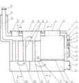
Fig. 1 is the main cutaway view of structure of the utility model the first embodiment;
Fig. 2 is the A-A view in Fig. 1;
Fig. 3 is the B-B view in Fig. 1;
Fig. 4 is the right view of Fig. 1;
Fig. 5 is the main cutaway view of structure of the utility model the second embodiment.
Mark in figure: 1. body of heater, 2 bells, 3. fire door, 4. burner hearth, 5. hearth water sleeve, 6. regulate cover body, 7. regulate button, 8. lever, 9. support bar, 10. baffle plate, 11. air inlet fence, 12. air scoops, 13. scarfing cinder end caps, 14. breast holes, 15. storage slag chambeies, 16. fire grates, 17. backhaul heating water jackets, 181. first row return smoke deferents, 182. second row return smoke deferents, 183. the 3rd flow back to journey flue tube, 184. the 4th flow back to journey flue tube, the 19. grey chambeies of storage, 20. first deashing chambeies, 21. first deashing top end covers, 22. second deashing chambeies, 23. second deashing top end covers, 24. chimneys, 25. chimney water sleeves, 26. drainage blower fans, 27. deashing side accents, 28. deashing side end caps, 29. return pipes, 30. outlet pipes.
The specific embodiment
Embodiment mono-
In Fig. 1, Fig. 2, a kind of many backhauls reverse burning heating stove, it comprises furnace shell 1, chimney 24, return pipe 29 and outlet pipe 30, is provided with successively fire door 3, burner hearth 4, fire grate 16, storage slag chamber 15 in the inside of furnace shell 1 from top to bottom, between furnace shell 1 and burner hearth 4, is provided with hearth water sleeve 5.
As shown in Figure 1 and Figure 2, fire door 3 is set to square, bell 2 cappings that match with fire door by it.Square fire door is convenient to coal-fired interpolation.
In Fig. 1, in the front end bottom of furnace shell 1, be provided with the breast hole 14 in a connection storage slag chamber 15, this breast hole 14 is by scarfing cinder end cap 13 cappings.Open scarfing cinder end cap 13, by breast hole 14, clear up easily cinder or the coal ash of the burning generation of storage slag chamber 15 interior storages.
As shown in Figure 1, be provided with the air scoop 12 of a connection burner hearth 4 in the front center of furnace shell 1, corresponding air scoop 12 is provided with conditioner.
As shown in Figure 1 and Figure 2, conditioner is the adjusting cover body 6 of seal welding one cover button air scoop 12 outside the front end of furnace shell 1, on adjusting cover body 6, has air inlet fence 11.In Fig. 1, in regulating cover body 6, be provided with the baffle plate 10 of capping air inlet fence 11, baffle plate 10 is connected with one end of a lever 8, the other end of this lever 8 and one regulates button 7 to be connected, regulate button 7 to be movably arranged on and regulate on cover body 6, the middle part movable supporting of lever 8 is on a support bar 9, and support bar 9 is fixedly connected on and regulates on cover body 6.When regulating the air input of air scoop 12, by pressing, regulate button 7 to drive baffle plates 10 through lever 8, sealing air inlet fence 11 or open the air inlet gap with air inlet fence 11, to control coal-fired burning velocity.
It should be noted that, conditioner also can have been adopted other structures.For example, on air scoop, establish an end cap, manually control the opening clearance between end cap and air scoop, to control air inflow and coal-fired burning velocity.
In Fig. 1, at the rear side of burner hearth 4, be provided with a backhaul heating water jacket 17 who is connected with hearth water sleeve 5.
As shown in Figure 1, Figure 3, be provided with a storage ash chamber 19 in backhaul heating water jacket 17 bottom, on this stores up the chamber wall in grey chamber 19, be provided with a deashing side accent 27, this deashing side accent 27 is by 28 cappings of deashing side end cap.Open deashing side end cap 28, by deashing side accent 27, clear up easily the coal ash falling in the grey chamber 19 of storage.
In Fig. 1, at backhaul heating water jacket 17 top, be provided with the first deashing chamber 20 and the second deashing chamber 22.The accent in the first deashing chamber 20 is by the first deashing top end cover 21 cappings.The accent in the second deashing chamber 22 is by the second deashing top end cover 23 cappings.
In Fig. 1, in storage slag chamber 15, store up between grey chamber 19 and the first deashing chamber 20, the second deashing chamber 22 and be provided with some journey flue tubes 18 that flow back to.
The number of return smoke deferent 18 rows depends on the size of coal-fired storage and heating area in burner hearth.Return smoke deferent 18 rows that the present embodiment adopts are three rows' technical scheme.As shown in Figure 3, often flowing back to journey flue tube is 5 and is arranged in parallel.
In Fig. 1, first row return smoke deferent 181 is connected storage slag chamber 15 with the first deashing chamber 20, and second row return smoke deferent 182 is connected the first deashing chamber 20 with the grey chamber 19 of storage, and the 3rd flows back to journey flue tube 183 is connected the grey chamber 19 of storage with the second deashing chamber 22.
As shown in Figure 1, the input of chimney 24 is connected with the second deashing chamber 22, and the output of chimney 24 is provided with a drainage blower fan 26.Drainage blower fan 26 can be controlled its drainage air quantity by the temperature electromagnetic sensor of a known use, also can Artificial Control drainage blower fan 26 start or stop, to control coal-fired burning velocity.
In Fig. 1, fire grate 16 is to be made by some horizontal water pipes, and the two ends of fire grate 16 are connected with backhaul heating water jacket 17, hearth water sleeve 5 respectively.The water pipe radical of fire grate depends on the size of burner hearth.As shown in Figure 2, the present embodiment fire grate adopts seven water pipes to make.
For waste heat is at utmost absorbed and used, at the circumferential hoop of chimney 25, be arranged with a chimney water sleeve 25 being connected with backhaul heating water jacket 17.
In Fig. 1, Fig. 2, outlet pipe 30 is connected with the internal upper part of chimney water sleeve 25, and return pipe 29 is connected with interior bottom of the backhaul heating water jacket 17.The water of the hearth water sleeve 5 of heating stove, backhaul heating water jacket 17 and chimney water sleeve 25 interior heating is through outlet pipe 30 outputs, and the heating piece of flowing through circulation is returned in hearth water sleeve 5, backhaul heating water jacket 17 and the chimney water sleeve 25 of heating stove by return pipe 29.
The combustion product that the burning of the utility model fire coal in burner hearth 4 produces, under drainage blower fan 26 or chimney 24 suctions, oppositely coal-fired layer of process burning, through coal-fired layer, further ignite and overheavy firing, gas and solid combustible in combustion product are fully burnt, carbon black in reduction discharge flue gas and the concentration of dust, reduce environmental pollution.
Water in the heat radiation heating furnace thorax water jacket 5 that coal-fired burning in burner hearth 4 produces.Carry the flue gas of heat is discharged by chimney 24 successively by 18 guiding of return smoke deferent after storing up slag chamber 15, the first deashing chamber 20, storing up grey chamber 19, the second deashing chamber 22, flue gas circulates in leading cigarette channel many backhauls are reciprocating, the heat heating backhaul heating water jacket 17 who carries, the water in chimney water sleeve 25, its calorific value is fully utilized.
Heating stove, after using certain hour, can adhere to black dirt in the inner tube of its return smoke deferent 18, affects the thermal efficiency.By the accent at the first deashing chamber 20,22 tops, the second deashing chamber, adopt cleaning hairbrush from up to down to clear up the black dirt on tube wall, black dirt drops on respectively storage slag chamber 15, stores up in grey chamber 19, then removes.The utility model at utmost keeps furnace wall clean, keeps optimal heat efficiency.
The utility model is reasonable in design, good heating effect, and fuel reverse burning is abundant, and the discharge capacity of pollutant is few, can economize on coal more than 50%.The heat that fired coal combustion produces circulates by the reciprocating cigarette channel of leading of many backhauls, has realized discharged at lower temperature, reduces heat and runs off, and calorific value utilization is reasonable, and the thermal efficiency can reach 90%.
Embodiment bis-
The present embodiment is different from embodiment mono-: return smoke deferent 18 rows have adopted four rows' technical scheme.Other structures are identical with embodiment mono-, and this seldom states.
As shown in Figure 5, return smoke deferent 18 rows have adopted four row's structures: wherein, first row return smoke deferent 181 is connected storage slag chamber 15 with the first deashing chamber 20, second row return smoke deferent 182 is connected the first deashing chamber 20 with the grey chamber 19 of storage, the 3rd flows back to journey flue tube 183 is connected the grey chamber 19 of storage with the second deashing chamber 22, the 4th flows back to journey flue tube 184 is connected the second deashing chamber 22 with chimney 24.
The present embodiment return smoke deferent 18 rows have adopted four row's structures, and flue gas has increased a backhaul in return smoke deferent, and the waste heat carrying in flue gas is further absorbed by backhaul heating water jacket 17, and it is reasonable that calorific value utilization is more tending towards.
Claims (4)
1. the heating stove of backhaul reverse burning more than a kind, it comprises furnace shell, chimney, return pipe and outlet pipe, in the inside of described furnace shell, be provided with successively fire door, burner hearth, fire grate, storage slag chamber from top to bottom, described fire door is by a bell capping, between furnace shell and burner hearth, be provided with hearth water sleeve, the breast hole that is provided with a connection storage slag chamber in the front end bottom of furnace shell, this breast hole, by a scarfing cinder end cap capping, is characterized in that:
In the front center of furnace shell, be provided with the air scoop of a connection burner hearth, to being provided with conditioner by air scoop;
Rear side at burner hearth is provided with a backhaul heating water jacket who is connected with hearth water sleeve, is provided with a storage ash chamber in this backhaul heating water jacket's bottom, on this stores up the chamber wall in grey chamber, is provided with a deashing side accent by the capping of deashing side end cap; At described backhaul heating water jacket's top, be provided with the first deashing chamber and the second deashing chamber, the first described deashing chamber, the accent in the second deashing chamber are corresponding to the first deashing top end cover, the second deashing top end cover capping respectively;
Between described ,Chu Hui chamber, storage slag chamber and described the first deashing chamber, the second deashing chamber, be provided with the return smoke deferent that some rows are arranged in parallel, described chimney is connected with described the second deashing chamber or return smoke deferent, and described return smoke deferent guiding flue gas is discharged by described chimney successively behind storage slag chamber, the first ,Chu Hui chamber, deashing chamber, the second deashing chamber;
Described fire grate is to be made by some horizontal water pipes, and the two ends of this fire grate are connected with backhaul heating water jacket, hearth water sleeve respectively;
On the output of described chimney, be provided with a drainage blower fan, at the circumferential hoop of chimney, be arranged with a chimney water sleeve being connected with backhaul heating water jacket;
Described outlet pipe is connected with the internal upper part of described chimney water sleeve, and described return pipe is connected with backhaul heating water jacket's interior bottom.
2. a kind of many backhauls reverse burning heating stove according to claim 1, it is characterized in that: described return smoke deferent is three rows, wherein, first row return smoke deferent is connected storage slag chamber with the first deashing chamber, second row return smoke deferent is connected the first Yu Chuhui chamber, deashing chamber, the 3rd flows back to journey flue tube is connected the grey chamber of storage with the second deashing chamber, the second described deashing chamber is connected with described chimney.
3. a kind of many backhauls reverse burning heating stove according to claim 1, it is characterized in that: described return smoke deferent is four rows, wherein, first row return smoke deferent is connected storage slag chamber with the first deashing chamber, second row return smoke deferent is connected the first Yu Chuhui chamber, deashing chamber, the 3rd flows back to journey flue tube is connected the grey chamber of storage with the second deashing chamber, the 4th flows back to journey flue tube is connected the second deashing chamber with described chimney.
4. according to a kind of many backhauls reverse burning heating stove described in claim 1 or 2 or 3, it is characterized in that: described conditioner, it is that the cover that is tightly connected in the front end outside of described furnace shell is buckled the adjusting cover body of air scoop, on this adjusting cover body, have air inlet fence, in regulating cover body, be provided with the baffle plate of capping air inlet fence, this baffle plate is connected with one end of a lever, the other end of this lever and one regulates button to be connected, and the middle part movable supporting of lever is on a support bar being fixedly connected with adjusting cover body.
Priority Applications (1)
| Application Number | Priority Date | Filing Date | Title |
|---|---|---|---|
| CN201320557381.4U CN203478344U (en) | 2013-09-06 | 2013-09-06 | Multi-return-stroke reverse combustion heating furnace |
Applications Claiming Priority (1)
| Application Number | Priority Date | Filing Date | Title |
|---|---|---|---|
| CN201320557381.4U CN203478344U (en) | 2013-09-06 | 2013-09-06 | Multi-return-stroke reverse combustion heating furnace |
Publications (1)
| Publication Number | Publication Date |
|---|---|
| CN203478344U true CN203478344U (en) | 2014-03-12 |
Family
ID=50226669
Family Applications (1)
| Application Number | Title | Priority Date | Filing Date |
|---|---|---|---|
| CN201320557381.4U Expired - Fee Related CN203478344U (en) | 2013-09-06 | 2013-09-06 | Multi-return-stroke reverse combustion heating furnace |
Country Status (1)
| Country | Link |
|---|---|
| CN (1) | CN203478344U (en) |
Cited By (4)
| Publication number | Priority date | Publication date | Assignee | Title |
|---|---|---|---|---|
| CN106224999A (en) * | 2016-08-06 | 2016-12-14 | 国能生源科技有限公司 | A kind of multiple stage circulation heat transfer efficient biomass combustion furnace |
| CN111189068A (en) * | 2018-11-15 | 2020-05-22 | 湖南三木龙威能源科技股份有限公司 | Biomass heat supply stove |
| CN111189069A (en) * | 2018-11-15 | 2020-05-22 | 湖南三木龙威能源科技股份有限公司 | Biomass heating device for indoor heating |
| CN111189067A (en) * | 2018-11-15 | 2020-05-22 | 湖南三木龙威能源科技股份有限公司 | Biomass water heater |
-
2013
- 2013-09-06 CN CN201320557381.4U patent/CN203478344U/en not_active Expired - Fee Related
Cited By (4)
| Publication number | Priority date | Publication date | Assignee | Title |
|---|---|---|---|---|
| CN106224999A (en) * | 2016-08-06 | 2016-12-14 | 国能生源科技有限公司 | A kind of multiple stage circulation heat transfer efficient biomass combustion furnace |
| CN111189068A (en) * | 2018-11-15 | 2020-05-22 | 湖南三木龙威能源科技股份有限公司 | Biomass heat supply stove |
| CN111189069A (en) * | 2018-11-15 | 2020-05-22 | 湖南三木龙威能源科技股份有限公司 | Biomass heating device for indoor heating |
| CN111189067A (en) * | 2018-11-15 | 2020-05-22 | 湖南三木龙威能源科技股份有限公司 | Biomass water heater |
Similar Documents
| Publication | Publication Date | Title |
|---|---|---|
| CN203478344U (en) | Multi-return-stroke reverse combustion heating furnace | |
| CN201652779U (en) | Vertical water-fire tube counter-burning gasification furnace | |
| CN103471137A (en) | Multiple-return-stroke reverse combustion heating boiler | |
| CN204880674U (en) | Living beings whirlwind gasification boiler | |
| CN201740221U (en) | Horizontal backfire normal-pressure boiler | |
| CN201066195Y (en) | Horizontal type reverse-combusting coal-firing boiler | |
| CN104654266A (en) | Water boiler with single boiler barrel and four return strokes | |
| CN204901741U (en) | Two -stage accent wind furnace that application is all -trans and is burnt fin formula water pipe grate | |
| CN201212729Y (en) | Biomass granular fuel boiler | |
| CN204829889U (en) | Domestic energy -concerving and environment -protective boiler | |
| CN201363889Y (en) | High-efficiency smokeless dust-removing and energy-saving heating stove | |
| CN202598825U (en) | Horizontal seawater special coal-fired furnace | |
| CN204922946U (en) | Utilize two -stage of fever fin formula water pipe grate that is all -trans to preheat wind boiler | |
| CN204757359U (en) | Fire boiler of rubbish | |
| CN205137544U (en) | Cooking heating stove with water pipe heat exchanger | |
| CN215892427U (en) | Biomass particle hot blast stove | |
| CN201621846U (en) | Smokeless dustless boiler | |
| CN202938363U (en) | Combined type coal-to-gas combustion heating furnace | |
| CN202630384U (en) | Multipurpose vertical and horizontal combined smokeless boiler | |
| CN219346799U (en) | Vertical multi-fuel high-efficiency hot water boiler | |
| CN204648330U (en) | A kind of saving furnace with secondary combustion structure | |
| CN202221088U (en) | Circulating fluidized incinerator | |
| CN202281258U (en) | Coal ball and coal dust secondary counter-burning four-season energy-saving boiler | |
| CN201811422U (en) | Horizontal multipass anti-burning boiler | |
| CN210117359U (en) | Novel gasification furnace |
Legal Events
| Date | Code | Title | Description |
|---|---|---|---|
| GR01 | Patent grant | ||
| GR01 | Patent grant | ||
| CF01 | Termination of patent right due to non-payment of annual fee |
Granted publication date: 20140312 Termination date: 20140906 |
|
| EXPY | Termination of patent right or utility model |