CN203456272U - Coil bag compressing machine - Google Patents
Coil bag compressing machine Download PDFInfo
- Publication number
- CN203456272U CN203456272U CN201320531943.8U CN201320531943U CN203456272U CN 203456272 U CN203456272 U CN 203456272U CN 201320531943 U CN201320531943 U CN 201320531943U CN 203456272 U CN203456272 U CN 203456272U
- Authority
- CN
- China
- Prior art keywords
- mentioned
- material platform
- coil bag
- cargo jack
- compressing
- Prior art date
- Legal status (The legal status is an assumption and is not a legal conclusion. Google has not performed a legal analysis and makes no representation as to the accuracy of the status listed.)
- Expired - Fee Related
Links
Images
Abstract
The utility model discloses a coil bag compressing machine. The coil bag compressing machine comprises a transmission mechanism, a coil bag compressing mechanism and a mechanical arm. The coil bag compressing mechanism comprises a material platform, a material compressing block and a connecting rod, wherein the material compressing block is arranged above the material platform. The material compressing block is vertically installed on the end portion of the connecting rod, and a sensor is arranged on the material platform, wherein the sensor is used for feeding back a material state so that whether the mechanical arm needs to work or not can be judged. The coil bag compressing machine has the advantages that the coil bag compressing machine is simple in structure, semi-automatic operation is achieved, and labor intensity is reduced. A coil bag can be compressed to be with an ideal size, and subsequence usage convenience is improved.
Description
Technical field
The utility model relates to a kind of cargo jack.
Background technology
Transformer coil is wound around and is made by enamelled wire or Copper Foil, owing to being wound around loosely, causes super large super thick, and it is very inconvenient to use, thus its volume need to be compressed to reduce its volume, thus improve the flexibility of using.
Summary of the invention
For solving the deficiencies in the prior art, the purpose of this utility model is to overcome the defect of prior art, and a kind of cargo jack is provided, and equipment cost is low, easy to use, the volume of line bag can be dwindled greatly.
In order to realize above-mentioned target, the utility model adopts following technical scheme:
A kind of cargo jack, comprise connecting gear, bundling mechanism and manipulator, above-mentioned bundling mechanism comprises: material platform, be arranged at binder block, the connecting rod of material platform top, above-mentioned binder block at right angle setting is in the end of connecting rod, thereby above-mentioned material platform is provided with transducer so that material state feedback is judged to whether manipulator needs action.
Aforementioned material platform is provided with a plurality of baffle plates so that the periphery of material to be pressed is fixed.
Aforementioned bundling mechanism is by air cylinder driven.
Aforementioned connecting gear comprises to material platform and transports the haul portion of material and the feeding portion that material is seen off from material platform.
Aforementioned connecting gear comprises delivery wheel and conveyer belt.
The end of aforementioned feeding portion arranges the container that gathers materials.
Usefulness of the present utility model is: cargo jack of the present utility model, and simple in structure, realized semiautomation operation, reduced labour intensity; Line bag pressure can be shortened into desirable volume, improve the convenience of follow-up use.
Accompanying drawing explanation
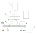
Fig. 1 is the structural representation of the specific embodiment of a kind of cargo jack of the present utility model.
The implication of Reference numeral in figure: 1, material platform, 2, binder block, 3, connecting rod, 4, line bag, 5, cylinder, 6, manipulator, 7, baffle plate, 8a, haul portion, 8b, feeding portion, 801, delivery wheel, 802, conveyer belt, 9, container gathers materials.
Embodiment
Below in conjunction with the drawings and specific embodiments, the utility model is done to concrete introduction.
Referring to Fig. 1, a kind of cargo jack of the present utility model, comprise connecting gear, bundling mechanism and manipulator 6, wherein, bundling mechanism comprises: material platform 1, the binder block 2 that is arranged at material platform 1 top and connecting rod 3, binder block 2 at right angle settings are in the end of connecting rod 3, line bag 4 to be compressed is positioned on material platform 1, and cylinder 5 drive link 3 drive binder block 2 to move downward, and line bag 4 is compressed to volume of ideal, so binder block 2 need to have certain deadweight.Manipulator 6 can be realized automatic clamping and placing material, so, on material platform 1, be provided with transducer so that thereby material state feedback is judged to whether manipulator 6 needs action, when Sensor monitoring has carried out after a pressing action to binder block 2, manipulator 6 moves immediately line bag that compression is completed and takes out and be placed on connecting gear.
For anti-principal vertical line bag 4 causes the increase of length and width in compression process, on material platform 1, be provided with a plurality of baffle plates 7 so that the periphery of material to be pressed is fixed, baffle plate 7 is mobilizable, can adjust flexibly according to demand position fixing.
Specifically, connecting gear comprises the 8b of feeding portion that transports the 8a of haul portion of material and material is seen off from material platform 1 to material platform 1.The 8a of haul portion and the 8b of feeding portion include delivery wheel 801 and conveyer belt 802.
Further, the container 9 that gathers materials is set in the end of feeding portion, the line bag having compressed is automatically sent to and gathers materials in container 9.
More than show and described basic principle of the present utility model, principal character and advantage.The technical staff of the industry should understand, and above-described embodiment does not limit the utility model in any form, and all employings are equal to replaces or technical scheme that the mode of equivalent transformation obtains, all drops in protection range of the present utility model.
Claims (6)
1. a cargo jack, it is characterized in that, comprise connecting gear, bundling mechanism and manipulator, above-mentioned bundling mechanism comprises: material platform, be arranged at binder block, the connecting rod of material platform top, above-mentioned binder block at right angle setting is in the end of connecting rod, thereby above-mentioned material platform is provided with transducer so that material state feedback is judged to whether manipulator needs action.
2. a kind of cargo jack according to claim 1, is characterized in that, above-mentioned material platform is provided with a plurality of baffle plates so that the periphery of material to be pressed is fixed.
3. a kind of cargo jack according to claim 1, is characterized in that, above-mentioned bundling mechanism is by air cylinder driven.
4. a kind of cargo jack according to claim 1, is characterized in that, above-mentioned connecting gear comprises to material platform and transports the haul portion of material and the feeding portion that material is seen off from material platform.
5. a kind of cargo jack according to claim 4, is characterized in that, above-mentioned connecting gear comprises delivery wheel and conveyer belt.
6. a kind of cargo jack according to claim 4, is characterized in that, the end of above-mentioned feeding portion arranges the container that gathers materials.
Priority Applications (1)
| Application Number | Priority Date | Filing Date | Title |
|---|---|---|---|
| CN201320531943.8U CN203456272U (en) | 2013-08-29 | 2013-08-29 | Coil bag compressing machine |
Applications Claiming Priority (1)
| Application Number | Priority Date | Filing Date | Title |
|---|---|---|---|
| CN201320531943.8U CN203456272U (en) | 2013-08-29 | 2013-08-29 | Coil bag compressing machine |
Publications (1)
| Publication Number | Publication Date |
|---|---|
| CN203456272U true CN203456272U (en) | 2014-02-26 |
Family
ID=50136131
Family Applications (1)
| Application Number | Title | Priority Date | Filing Date |
|---|---|---|---|
| CN201320531943.8U Expired - Fee Related CN203456272U (en) | 2013-08-29 | 2013-08-29 | Coil bag compressing machine |
Country Status (1)
| Country | Link |
|---|---|
| CN (1) | CN203456272U (en) |
Cited By (2)
| Publication number | Priority date | Publication date | Assignee | Title |
|---|---|---|---|---|
| CN103440976A (en) * | 2013-08-29 | 2013-12-11 | 昆山达功电子有限公司 | Coil bag pressing machine |
| CN103943350A (en) * | 2014-04-04 | 2014-07-23 | 昆山达功电子有限公司 | Coil thickness detection and correction device |
-
2013
- 2013-08-29 CN CN201320531943.8U patent/CN203456272U/en not_active Expired - Fee Related
Cited By (2)
| Publication number | Priority date | Publication date | Assignee | Title |
|---|---|---|---|---|
| CN103440976A (en) * | 2013-08-29 | 2013-12-11 | 昆山达功电子有限公司 | Coil bag pressing machine |
| CN103943350A (en) * | 2014-04-04 | 2014-07-23 | 昆山达功电子有限公司 | Coil thickness detection and correction device |
Similar Documents
| Publication | Publication Date | Title |
|---|---|---|
| CN208583865U (en) | A kind of automatic punch | |
| CN203456272U (en) | Coil bag compressing machine | |
| CN204296077U (en) | Quickly discharging formula iron filings cuber | |
| CN203649901U (en) | Mounting machine for air spring | |
| CN205703208U (en) | A kind of suspension ring erecting device being linked with Full-automatic assembling machine | |
| CN202804611U (en) | Pressing device of junction box supports | |
| CN204664083U (en) | Panel and substrate assembly tooling | |
| CN103440976A (en) | Coil bag pressing machine | |
| CN203994150U (en) | A kind of adobe compression mold device of insulating brick | |
| CN203526367U (en) | Automatic rivet pressing machine | |
| CN203312267U (en) | Pin repair device of integrated circuit | |
| CN104760912A (en) | Paint barrel sealing device | |
| CN205056384U (en) | Automatic rubber coating equipment of motor shell dress magnetic shoe | |
| CN203382236U (en) | Bucket-wheel stacker-reclaimer with wireless control device | |
| CN204182714U (en) | Tubing mechanized production system | |
| CN203830234U (en) | 46-station air filter PU end cover glue injection curing device | |
| CN203753955U (en) | Carrying mechanism | |
| CN207057998U (en) | A kind of c-type back-up ring pressing mechanism | |
| CN202180499U (en) | Fabric and board pressing device used for automobile | |
| CN202216621U (en) | Automatic crimping machine for electronic detonators | |
| CN203497767U (en) | Silo with electric lifting device | |
| CN204550041U (en) | For the Wrapping apparatus of Sofa cushion | |
| CN104627417B (en) | A kind of description shifting apparatus of automatic remote-control device baling press | |
| CN205309655U (en) | Pneumatic welding discharging device of induction type | |
| CN204224661U (en) | Bend pipe stress eliminating equipment |
Legal Events
| Date | Code | Title | Description |
|---|---|---|---|
| C14 | Grant of patent or utility model | ||
| GR01 | Patent grant | ||
| CF01 | Termination of patent right due to non-payment of annual fee |
Granted publication date: 20140226 Termination date: 20140829 |
|
| EXPY | Termination of patent right or utility model |