CN203439685U - Rotary stand of chair conveying line - Google Patents
Rotary stand of chair conveying line Download PDFInfo
- Publication number
- CN203439685U CN203439685U CN201320339698.0U CN201320339698U CN203439685U CN 203439685 U CN203439685 U CN 203439685U CN 201320339698 U CN201320339698 U CN 201320339698U CN 203439685 U CN203439685 U CN 203439685U
- Authority
- CN
- China
- Prior art keywords
- bracing frame
- support frame
- rotating table
- conveyor line
- conveying assembly
- Prior art date
- Legal status (The legal status is an assumption and is not a legal conclusion. Google has not performed a legal analysis and makes no representation as to the accuracy of the status listed.)
- Expired - Fee Related
Links
Images

Abstract
The utility model discloses a rotary stand of a chair conveying line. The rotary stand is characterized by comprising a pedestal, a bracing frame and a conveying assembly; the conveying assembly is fixed to the bracing frame; a driving device for driving the bracing frame to rotate is disposed between the pedestal and the bracing frame; and a balance device for keeping the bracing frame rotating in a balanced manner is also disposed between the pedestal and the bracing frame. The driving device is adopted to drive the bracing frame to rotate on the pedestal, the conveying assembly is mounted on the bracing frame, and the balance device for keeping the bracing frame rotating in a balanced manner is disposed between the bracing frame and the pedestal. Through the above technical solution, the rotary stand has the following advantages: goods that are being conveyed can be swerved without an increase of workload of workers, and the balance device is employed to ensure that the bracing frame keeps balanced during rotation.
Description
Technical field
The utility model relates to the rotating table in manufacturing line load transfer device field, particularly a kind of seat conveyor line.
Background technology
In manufacturing line transportation art, the conveying of goods be unable to do without flow production line, and when some goods need to turn to, general employing is manually transported goods, by cargo transportation to another manufacturing line.But, adopting the Steering that manually completes goods, labor strength is large, and degree of automation is low, and transport efficiency is low.
Utility model content
Problem to be solved in the utility model is to provide a kind of simple in structure, the rotating table of the seat conveyor line that degree of automation is high.
In order to solve the problems of the technologies described above, the utility model adopts following technical scheme: a kind of rotating table of seat conveyor line, it is characterized in that: comprise base, bracing frame and conveying assembly, described conveying assembly is fixed on support frame as described above, between described base and support frame as described above, be provided with the actuating device that drives bracing frame rotation, between support frame as described above and described base, be also provided with the balancing device that maintains support frame as described above spin balancing.
Improved, described actuating device comprises S. A. and cylinder, and described S. A. is located at the middle part of support frame as described above and described base, described air cylinder driven support frame as described above rotation.
Improved, described balancing device comprises revolving wheel and swing-around trajectory, and described revolving wheel is installed on support frame as described above bottom, and described swing-around trajectory is located on described base, and described revolving wheel turns round on described swing-around trajectory by described S. A..
Improved, described swing-around trajectory is circular.
Improved, described conveying assembly comprises carries motor, roller mechanism and guardrail running roller, and described roller mechanism comprises roller and support, and described guardrail running roller is located on the support of described roller both sides, and described roller is by carrying motor-driven power.
Improved, between the conveying end of described conveying assembly and support frame as described above, be provided with pneumatic stopper.
Improved, also comprise travel switch, described travel switch provides instruction to described pneumatic stopper, cylinder and conveying motor.
The beneficial effects of the utility model:
In the utility model, by actuating device, drive bracing frame to rotate on base, conveying assembly is installed on bracing frame, simultaneously, between bracing frame and base, be provided with the balancing device that maintains bracing frame spin balancing, adopt after technique scheme, the utlity model has following advantage: in the situation that not increasing workman's labour power, can complete the problem that the goods in carrying is turned to, meanwhile, the balancing device being provided with, can guarantee that bracing frame keeps balance in rotary course.
Accompanying drawing explanation
Below in conjunction with accompanying drawing, the specific embodiment of the present utility model is described further:
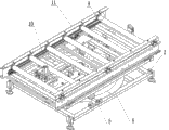
Fig. 1 is the structural representation of the rotating table of the utility model seat conveyor line;
Fig. 2 is the partial enlarged drawing at A place in Fig. 1;
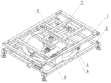
Fig. 3 is the schematic diagram after the assembling of base and bracing frame in Fig. 1.
The specific embodiment
As shown in Fig. 1 or Fig. 3, a kind of rotating table of seat conveyor line, it is characterized in that: comprise base 2, bracing frame 1 and conveying assembly, described conveying assembly is fixed on support frame as described above 1, between described base 2 and support frame as described above 1, be provided with the actuating device that drives bracing frame 1 rotation, between support frame as described above 1 and described base 2, be also provided with the balancing device that maintains support frame as described above 1 spin balancing.Conveying assembly is located on the bracing frame 1 of rotation, when goods needs to turn on conveying assembly, actuating device drives bracing frame 1 to rotate a certain angle, and then conveying assembly sends out goods, thereby complete turning to of goods, meanwhile, between bracing frame 1 and base 2, be provided with the balancing device that maintains bracing frame 1 spin balancing, can make bracing frame 1 more steady in rotary course, simultaneously, the setting of balancing device, has improved the stability of equipment, makes the longer service life of equipment.
In above embodiment, described actuating device comprises S. A. 4 and cylinder 7, and described S. A. 4 is located at the middle part of support frame as described above 1 and described base 2, and described cylinder 7 drives support frames as described above 1 rotation.Because bracing frame 1 and the middle part of base 2 are provided with S. A. 4, the piston rod of cylinder 7 is flexibly connected with bracing frame 1 bottom, starts cylinder, and piston rod promotes after bracing frame 1, and owing to there being the effect of S. A. 4, bracing frame 1 is around S. A. 4 rotations.
Except actuating device, also comprise balancing device, described balancing device comprises revolving wheel 5 and swing-around trajectory 6, described revolving wheel 5 is installed on support frame as described above 1 bottom, described swing-around trajectory 6 is located on described base 2, described revolving wheel 5 turns round on described swing-around trajectory 6 by described S. A. 4, when bracing frame 1 is when rotating, and then motion on swing-around trajectory 6 of revolving wheel 5, in this embodiment, the installation of revolving wheel 5 will be from S. A. 4 a little further, and so weight that can make bracing frame 1 bear is larger.
The swing-around trajectory 6 more than adopting is circular, track width will just be applicable to revolving wheel 5 and turn round in the above, simultaneously, reason due to the conveying assembly on bracing frame 1, the pressure ratio that swing-around trajectory 6 is subject to by revolving wheel is larger, therefore on the material of swing-around trajectory 6, preferably adopt the alloy material that intensity is larger, as: aluminum alloy materials or high-carbon steel material.
As shown in Figure 2 or Figure 3, conveying assembly on bracing frame 1 comprises carries motor 3, roller mechanism and guardrail running roller 9, described roller mechanism comprises roller 8 and support 11, described guardrail running roller 9 is located on the support 11 of described roller 8 both sides, described roller 8 is by carrying motor 3 transfer motion powers, on the support 11 of roller 8 both sides, guardrail running roller 9 is installed, owing to carrying motor 3 driving rollers 8, therefore, the goods of carrying in roller mechanism is with certain speed, under the effect of guardrail running roller 9, can avoid the goods of conveying and 11 collisions of the support of both sides by actv., reduce friction between the two and the power of conveying.
In order to stop the goods of carrying on conveying assembly, between the conveying end of conveying assembly and support frame as described above 1, be provided with pneumatic stopper 10.
In above embodiment, also comprise travel switch, described travel switch provides instruction to described pneumatic stopper 10, cylinder 7 and carries motor 3, the signal that puts in place is sent by travel switch, compare photoelectric switch or magnetic switch, not only can avoid other as the interference of power supply, and cost is lower.
Except above preferred embodiment, the utility model also has other embodiment, those skilled in the art can make various changes and distortion according to the utility model, only otherwise depart from spirit of the present utility model, all should belong to the defined scope of the utility model claims.
Claims (7)
1. the rotating table of a seat conveyor line, it is characterized in that: comprise base, bracing frame and conveying assembly, described conveying assembly is fixed on support frame as described above, between described base and support frame as described above, be provided with the actuating device that drives bracing frame rotation, between support frame as described above and described base, be also provided with the balancing device that maintains support frame as described above spin balancing.
2. the rotating table of seat conveyor line according to claim 1, is characterized in that: described actuating device comprises S. A. and cylinder, and described S. A. is located at the middle part of support frame as described above and described base, described air cylinder driven support frame as described above rotation.
3. the rotating table of seat conveyor line according to claim 2, it is characterized in that: described balancing device comprises revolving wheel and swing-around trajectory, described revolving wheel is installed on support frame as described above bottom, described swing-around trajectory is located on described base, and described revolving wheel turns round on described swing-around trajectory by described S. A..
4. the rotating table of seat conveyor line according to claim 3, is characterized in that: described swing-around trajectory is for circular.
5. the rotating table of seat conveyor line according to claim 2, it is characterized in that: described conveying assembly comprises carries motor, roller mechanism and guardrail running roller, described roller mechanism comprises roller and support, described guardrail running roller is located on the support of described roller both sides, and described roller is by carrying motor-driven power.
6. the rotating table of seat conveyor line according to claim 5, is characterized in that: between the conveying end of described conveying assembly and support frame as described above, be provided with pneumatic stopper.
7. the rotating table of seat conveyor line according to claim 6, is characterized in that: also comprise travel switch, described travel switch provides instruction to described pneumatic stopper, cylinder and conveying motor.
Priority Applications (1)
| Application Number | Priority Date | Filing Date | Title |
|---|---|---|---|
| CN201320339698.0U CN203439685U (en) | 2013-06-09 | 2013-06-09 | Rotary stand of chair conveying line |
Applications Claiming Priority (1)
| Application Number | Priority Date | Filing Date | Title |
|---|---|---|---|
| CN201320339698.0U CN203439685U (en) | 2013-06-09 | 2013-06-09 | Rotary stand of chair conveying line |
Publications (1)
| Publication Number | Publication Date |
|---|---|
| CN203439685U true CN203439685U (en) | 2014-02-19 |
Family
ID=50090753
Family Applications (1)
| Application Number | Title | Priority Date | Filing Date |
|---|---|---|---|
| CN201320339698.0U Expired - Fee Related CN203439685U (en) | 2013-06-09 | 2013-06-09 | Rotary stand of chair conveying line |
Country Status (1)
| Country | Link |
|---|---|
| CN (1) | CN203439685U (en) |
Cited By (8)
| Publication number | Priority date | Publication date | Assignee | Title |
|---|---|---|---|---|
| CN103332480A (en) * | 2013-06-09 | 2013-10-02 | 湖州科尼物流设备有限公司 | Rotating platform for seat conveying line |
| CN105016062A (en) * | 2015-08-04 | 2015-11-04 | 全友家私有限公司 | 90-degree plate rotating machine |
| WO2016074563A1 (en) * | 2014-11-13 | 2016-05-19 | 中车青岛四方机车车辆股份有限公司 | Conveying apparatus for rail vehicle seat |
| CN106494868A (en) * | 2016-12-01 | 2017-03-15 | 广州市亚丹柜业有限公司 | A kind of 360 degree of tote carts |
| CN106516694A (en) * | 2016-12-27 | 2017-03-22 | 无锡明珠钢球有限公司 | Rotary conveying device of assembly line |
| CN108861516A (en) * | 2018-07-18 | 2018-11-23 | 绍兴市中等专业学校 | A kind of rotationally conveying device of prefabricated plate |
| CN109160250A (en) * | 2018-07-17 | 2019-01-08 | 芜湖万向新元环保科技有限公司 | A kind of modified steering conveyor |
| CN112678416A (en) * | 2021-03-12 | 2021-04-20 | 诸城市锦翔汽车内饰有限公司 | Conveying equipment for automobile seat workshop |
-
2013
- 2013-06-09 CN CN201320339698.0U patent/CN203439685U/en not_active Expired - Fee Related
Cited By (11)
| Publication number | Priority date | Publication date | Assignee | Title |
|---|---|---|---|---|
| CN103332480A (en) * | 2013-06-09 | 2013-10-02 | 湖州科尼物流设备有限公司 | Rotating platform for seat conveying line |
| WO2016074563A1 (en) * | 2014-11-13 | 2016-05-19 | 中车青岛四方机车车辆股份有限公司 | Conveying apparatus for rail vehicle seat |
| GB2542062A (en) * | 2014-11-13 | 2017-03-08 | Crrc Qingdao Sifang Co Ltd | Conveying apparatus for rail vehicle seat |
| GB2542062B (en) * | 2014-11-13 | 2017-08-09 | Crrc Qingdao Sifang Co Ltd | Conveying apparatus for rail vehicle seat |
| CN105016062A (en) * | 2015-08-04 | 2015-11-04 | 全友家私有限公司 | 90-degree plate rotating machine |
| CN105016062B (en) * | 2015-08-04 | 2017-02-01 | 全友家私有限公司 | 90-degree plate rotating machine |
| CN106494868A (en) * | 2016-12-01 | 2017-03-15 | 广州市亚丹柜业有限公司 | A kind of 360 degree of tote carts |
| CN106516694A (en) * | 2016-12-27 | 2017-03-22 | 无锡明珠钢球有限公司 | Rotary conveying device of assembly line |
| CN109160250A (en) * | 2018-07-17 | 2019-01-08 | 芜湖万向新元环保科技有限公司 | A kind of modified steering conveyor |
| CN108861516A (en) * | 2018-07-18 | 2018-11-23 | 绍兴市中等专业学校 | A kind of rotationally conveying device of prefabricated plate |
| CN112678416A (en) * | 2021-03-12 | 2021-04-20 | 诸城市锦翔汽车内饰有限公司 | Conveying equipment for automobile seat workshop |
Similar Documents
| Publication | Publication Date | Title |
|---|---|---|
| CN203439685U (en) | Rotary stand of chair conveying line | |
| CN103332480A (en) | Rotating platform for seat conveying line | |
| CN203439680U (en) | Rotary stand of tire conveying line | |
| CN103332479B (en) | A kind of rotating table of tyre conveying line | |
| CN201770273U (en) | Speed chain type assembly line | |
| CN206050954U (en) | A kind of glass placing rack with transport function | |
| CN103121586B (en) | Straight-line-intersected belt-type sorting machine | |
| CN201660296U (en) | Improved conveyer | |
| CN201737461U (en) | Double-chain roll table swing machine | |
| CN106733506B (en) | Glue spraying device for bottom cover of steel drum | |
| CN203143662U (en) | 90-degree rotation conveying mechanism | |
| CN204400118U (en) | Full automaticity truck 90 degree of reversing arrangements | |
| CN204341832U (en) | A kind of convertible conveyer | |
| CN106006378A (en) | Rotatable electric hoist type crane | |
| CN202864215U (en) | Magnetic steel sticking roller way | |
| CN106392749B (en) | A kind of feed mechanism that can quickly commutate | |
| CN207482784U (en) | A kind of material conveyor | |
| CN204137756U (en) | Casting Parts sprays paint feedway | |
| CN210127060U (en) | Hoisting structure for high-level logistics conveying equipment | |
| CN202729142U (en) | Single-chain trolley conveying line | |
| CN208593796U (en) | A kind of sorting device for avoiding logistics goods from damaging | |
| CN201240654Y (en) | Transportation ground roller with bearing | |
| CN203853397U (en) | Winding turning device | |
| CN207536635U (en) | A kind of conveyer device for Railway Freight Transportation | |
| CN212333679U (en) | Rotary roller way conveyor |
Legal Events
| Date | Code | Title | Description |
|---|---|---|---|
| C14 | Grant of patent or utility model | ||
| GR01 | Patent grant | ||
| CF01 | Termination of patent right due to non-payment of annual fee |
Granted publication date: 20140219 Termination date: 20170609 |
|
| CF01 | Termination of patent right due to non-payment of annual fee |