CN203375120U - Fixing device for measuring apparatus - Google Patents
Fixing device for measuring apparatus Download PDFInfo
- Publication number
- CN203375120U CN203375120U CN201320448933.8U CN201320448933U CN203375120U CN 203375120 U CN203375120 U CN 203375120U CN 201320448933 U CN201320448933 U CN 201320448933U CN 203375120 U CN203375120 U CN 203375120U
- Authority
- CN
- China
- Prior art keywords
- fixing device
- driving device
- measuring apparatus
- pedestal
- flexible rod
- Prior art date
- Legal status (The legal status is an assumption and is not a legal conclusion. Google has not performed a legal analysis and makes no representation as to the accuracy of the status listed.)
- Expired - Fee Related
Links
Images

Abstract
The utility model discloses a fixing device for a measuring apparatus. The fixing device comprises a base, wherein tapered feet are distributed at the bottom of the base, a telescopic rod is fixedly installed at the upper portion of the base and connected with a telescopic driving device, the telescopic driving device is fixed on the base, and a measuring apparatus mounting table is fixedly installed at the end of the telescopic rod. The tapered feet can be conveniently inserted into soil, usage of the measuring apparatus on the geological-soft measurement face is facilitated, and the height of the telescopic rod can be changed and the height of the measuring apparatus can be indirectly adjusted by utilizing the telescopic driving device, so that usage of measurers with different heights is facilitated, and the fixing device for the measuring apparatus is convenient to use.
Description
Technical field
The utility model relates to a kind of measurement Assisted Facility, relates in particular to a kind of fixing device for the fixation measuring instrument.
Background technique
When building, engineering survey, theodolite, leveling instrument are indispensable measuring tools, and above-mentioned instrument, when being measured, must utilize the measurement support to fix on the ground, to guarantee its quiet stability.And measurement support of the prior art generally only is provided with the body of rod of a fixed length, in body of rod bottom, a tripod is installed, during measurement, utilize tripod that the body of rod and measuring tool are supported and fix, above-mentioned measurement support in use, if run into strong wind weather, easily the measurement support is blown down, thereby the damage measuring tool, cause survey data inaccurate simultaneously, measure efficiency low, if while using on softer sand ground in geology, measure support fixing more unstable.
Summary of the invention
Technical problem to be solved in the utility model is to provide a kind of simple in structure, convenient fixing, stable detector fixing device.
For solving the problems of the technologies described above, the technical solution of the utility model is: the detector fixing device, comprise pedestal, described base bottom is distributed with the cone pin, described pedestal top is installed with flexible rod, described flexible rod is connected with retractable driving device, and described retractable driving device is fixed on described pedestal, and the end of described flexible rod is installed with the detector mounting platform.
As preferred technological scheme, described retractable driving device comprises the oil hydraulic pump be fixed on described pedestal, is rotatablely equipped with the hydraulic operation bar on described oil hydraulic pump, and described hydraulic operation bar front end is articulated on described pedestal by pole.
As preferred technological scheme, described pedestal is set to frustum cone structure, and described cone pin at least arranges three, and is distributed in described base bottom.
As to improvement of the technical scheme, on described flexible rod, be installed with handle.
Owing to having adopted technique scheme, the detector fixing device, comprise pedestal, described base bottom is distributed with the cone pin, described pedestal top is installed with flexible rod, described flexible rod is connected with retractable driving device, and described retractable driving device is fixed on described pedestal, and the end of described flexible rod is installed with the detector mounting platform; The beneficial effects of the utility model are: the cone pin can be inserted in soil easily, be convenient for measuring on the measurement face that instrument is softer in geology and use, utilize retractable driving device can change the height of flexible rod, the height of Indirect method surveying instrument, use with the survey crew that facilitates different heights, use convenient.
the accompanying drawing explanation
The following drawings only is intended to the utility model is done and schematically illustrated and explain, does not limit scope of the present utility model.Wherein:
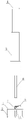
Fig. 1 is the utility model embodiment's structural representation;
Fig. 2 is the utility model embodiment's side view;
In figure: the 1-pedestal; 2-bores pin; The 3-flexible rod; 4-detector mounting platform; The 5-oil hydraulic pump; 6-hydraulic operation bar; 7-pole; The 8-handle.
Embodiment
Below in conjunction with drawings and Examples, further set forth the utility model.In the following detailed description, only by the mode of explanation, some example embodiment of the present utility model has been described.Undoubtedly, those of ordinary skill in the art can recognize, in the situation that do not depart from spirit and scope of the present utility model, can to described embodiment, be revised by various mode.Therefore, accompanying drawing is illustrative with being described in essence, rather than for limiting the protection domain of claim.
As depicted in figs. 1 and 2, the detector fixing device, comprise pedestal 1, described pedestal 1 bottom is distributed with cone pin 2, the described pedestal 1 of the present embodiment is set to frustum cone structure, and described cone pin 2 at least arranges three, and is distributed in described pedestal 1 bottom, cone pin 2 in the present embodiment arranges four, the stability while measuring to improve.In use, cone pin 2 can be inserted in the softer measurement face of quality, can effectively prevent from being blown to by strong wind, thereby protect detector, improve measurement efficiency simultaneously.
Described pedestal 1 top is installed with flexible rod 3, described flexible rod 3 is connected with retractable driving device, and described retractable driving device is fixed on described pedestal 1, the end of described flexible rod 3 is installed with detector mounting platform 4, described retractable driving device comprises the oil hydraulic pump 5 be fixed on described pedestal 1, be rotatablely equipped with hydraulic operation bar 6 on described oil hydraulic pump 5, described hydraulic operation bar 6 front ends are articulated on described pedestal 1 by pole 7, by operation hydraulic operation bar 6, can control the lifting of flexible rod 3, simple to operate, easy to use.
In order to improve the being convenient for carrying property of the present embodiment, can on described flexible rod 3, be installed with handle 8.
Description of the present utility model provides for example with for the purpose of describing, and is not exhaustively or by the utility model to be limited to disclosed form.Many modifications and variations are obvious for the ordinary skill in the art.Selecting and describing embodiment is for better explanation principle of the present utility model and practical application, thereby and makes those of ordinary skill in the art can understand the various embodiments with various modifications that the utility model design is suitable for special-purpose.
Claims (4)
1. detector fixing device, it is characterized in that: comprise pedestal, described base bottom is distributed with the cone pin, described pedestal top is installed with flexible rod, described flexible rod is connected with retractable driving device, and described retractable driving device is fixed on described pedestal, and the end of described flexible rod is installed with the detector mounting platform.
2. detector fixing device as claimed in claim 1, it is characterized in that: described retractable driving device comprises the oil hydraulic pump be fixed on described pedestal, be rotatablely equipped with the hydraulic operation bar on described oil hydraulic pump, described hydraulic operation bar front end is articulated on described pedestal by pole.
3. detector fixing device as claimed in claim 1, it is characterized in that: described pedestal is set to frustum cone structure, and described cone pin at least arranges three, and is distributed in described base bottom.
4. as claim 1,2 or 3 described detector fixing devices, it is characterized in that: on described flexible rod, be installed with handle.
Priority Applications (1)
| Application Number | Priority Date | Filing Date | Title |
|---|---|---|---|
| CN201320448933.8U CN203375120U (en) | 2013-07-26 | 2013-07-26 | Fixing device for measuring apparatus |
Applications Claiming Priority (1)
| Application Number | Priority Date | Filing Date | Title |
|---|---|---|---|
| CN201320448933.8U CN203375120U (en) | 2013-07-26 | 2013-07-26 | Fixing device for measuring apparatus |
Publications (1)
| Publication Number | Publication Date |
|---|---|
| CN203375120U true CN203375120U (en) | 2014-01-01 |
Family
ID=49837649
Family Applications (1)
| Application Number | Title | Priority Date | Filing Date |
|---|---|---|---|
| CN201320448933.8U Expired - Fee Related CN203375120U (en) | 2013-07-26 | 2013-07-26 | Fixing device for measuring apparatus |
Country Status (1)
| Country | Link |
|---|---|
| CN (1) | CN203375120U (en) |
Cited By (2)
| Publication number | Priority date | Publication date | Assignee | Title |
|---|---|---|---|---|
| CN104482372A (en) * | 2014-12-08 | 2015-04-01 | 河北汉光重工有限责任公司 | Heavy-load large-stroke high-stability parallel pneumatic lifting mechanism |
| CN109270227A (en) * | 2018-12-03 | 2019-01-25 | 海宁市英德赛电子有限公司 | Ammonia detection device in high-purity ammonia production system |
-
2013
- 2013-07-26 CN CN201320448933.8U patent/CN203375120U/en not_active Expired - Fee Related
Cited By (2)
| Publication number | Priority date | Publication date | Assignee | Title |
|---|---|---|---|---|
| CN104482372A (en) * | 2014-12-08 | 2015-04-01 | 河北汉光重工有限责任公司 | Heavy-load large-stroke high-stability parallel pneumatic lifting mechanism |
| CN109270227A (en) * | 2018-12-03 | 2019-01-25 | 海宁市英德赛电子有限公司 | Ammonia detection device in high-purity ammonia production system |
Similar Documents
| Publication | Publication Date | Title |
|---|---|---|
| CN203671183U (en) | Detecting instrument A-frame | |
| CN211399192U (en) | Bracket rod for mine survey | |
| CN203375120U (en) | Fixing device for measuring apparatus | |
| CN103591929A (en) | Leveling rod for measuring subsidence of ground with large surface relief and use method thereof | |
| CN207123280U (en) | A kind of novel building engineering surveying instrument | |
| CN207528224U (en) | A kind of bridge pier tilt detecting device | |
| CN205067767U (en) | Gravity vertical gradient measurement bay | |
| CN203116729U (en) | Plumb-line rod | |
| CN210533379U (en) | Easy fixed marker post for architectural survey | |
| CN210689598U (en) | Engineering survey surveyor's level strutting arrangement | |
| CN208043047U (en) | A kind of road and bridge construction device | |
| CN205576657U (en) | Portable track lifting elevation chi of railway | |
| CN212620722U (en) | Slope gradient measuring device | |
| CN104141866A (en) | Supporting device for instrument erection | |
| CN204479069U (en) | Mapping levelling staff balance and stability F type foot rest | |
| CN204831279U (en) | Building subsides to warp to measure uses indium steel ruler | |
| CN211976420U (en) | Novel support of surveying instrument device | |
| CN204788208U (en) | Portable structure of rock mass face friction angle measuring device | |
| CN204427148U (en) | A kind of geological survey drawing support frame device | |
| CN207881689U (en) | A kind of land surveying Sopwith staff | |
| CN202573503U (en) | Novel compass | |
| CN202582529U (en) | Open pit mine slope angle measuring instrument | |
| CN204960781U (en) | Take ladder of spirit level | |
| CN211717450U (en) | A sighting rod for engineering survey | |
| CN104359469A (en) | Suspension wire device |
Legal Events
| Date | Code | Title | Description |
|---|---|---|---|
| C14 | Grant of patent or utility model | ||
| GR01 | Patent grant | ||
| CF01 | Termination of patent right due to non-payment of annual fee | ||
| CF01 | Termination of patent right due to non-payment of annual fee |
Granted publication date: 20140101 Termination date: 20180726 |