CN203247717U - Connecting node of concrete column and steel beam - Google Patents
Connecting node of concrete column and steel beam Download PDFInfo
- Publication number
- CN203247717U CN203247717U CN 201320254491 CN201320254491U CN203247717U CN 203247717 U CN203247717 U CN 203247717U CN 201320254491 CN201320254491 CN 201320254491 CN 201320254491 U CN201320254491 U CN 201320254491U CN 203247717 U CN203247717 U CN 203247717U
- Authority
- CN
- China
- Prior art keywords
- steel
- concrete column
- steel sleeve
- steel bushing
- sleeve
- Prior art date
- Legal status (The legal status is an assumption and is not a legal conclusion. Google has not performed a legal analysis and makes no representation as to the accuracy of the status listed.)
- Expired - Fee Related
Links
Images


Landscapes
- Joining Of Building Structures In Genera (AREA)
Abstract
本实用新型提供了一种混凝土柱与钢梁的连接节点,属于建筑工程技术领域。它解决了现有混凝土柱与钢梁的连接节点强度较低、施工困难等技术问题。一种混凝土柱与钢梁的连接节点,包括混凝土柱和钢梁,本节点包括半钢套一和半钢套二,半钢套一和半钢套二可拆卸连接且连接后能够套设在混凝土柱上;半钢套一和/或半钢套二上固连有连接臂,连接臂与钢梁可拆卸连接;混凝土柱上设置有凸肩,半钢套一和半钢套二能够抵靠在凸肩上。本实用新型具有强度高、施工简单等优点。
The utility model provides a connection node between a concrete column and a steel beam, which belongs to the technical field of construction engineering. It solves the technical problems such as low strength of connection nodes between existing concrete columns and steel beams and difficult construction. A connection node between a concrete column and a steel beam, including a concrete column and a steel beam. This node includes a half-steel sleeve 1 and a half-steel sleeve 2. The first half-steel sleeve and the second half-steel sleeve are detachably connected and can be sleeved on On the concrete column; the first half-steel sleeve and/or the second half-steel sleeve are fixedly connected with a connecting arm, and the connecting arm is detachably connected to the steel beam; the concrete column is provided with a shoulder, and the first half-steel sleeve and the second half-steel sleeve can withstand Lean on the shoulders. The utility model has the advantages of high strength, simple construction and the like.
Description
技术领域technical field
本实用新型属于建筑工程技术领域,涉及一种混凝土柱与钢梁的连接节点。The utility model belongs to the technical field of construction engineering and relates to a connection node between a concrete column and a steel beam.
背景技术Background technique
当前混凝土柱与钢梁的连接节点的做法一般为:在混凝土柱中植入钢筋并焊接连接件,如专利(200910208481.4)中公开的一种新型混凝土柱-钢梁组合框架结构节点,包括钢梁、混凝土柱、连接端板和高强度连接螺栓,混凝土柱包括方形钢板桶、纵向钢筋和复数块加劲钢板,各个加劲钢板设置与方形钢板桶内将方形钢板桶的横截方向分隔为复数块分格,各加劲钢板与方形钢板桶焊接呈衣蛾整体,纵向钢筋分别从分格内穿过,钢梁通过连接端板与高强连接螺栓连接在方形钢板桶的外桶壁上,不难看出,该方案施工较为复杂,难度较大,而且,梁柱与钢梁之间的剪力几乎全部由高强螺栓承受,长时间之后,螺栓腐蚀、强度减弱,无法进行修复,由无法修复带来的安全隐患极大,不利于建筑的安全性和可靠性;The current practice of connecting nodes between concrete columns and steel beams is generally: implant steel bars in concrete columns and weld the connectors, such as a new type of concrete column-steel beam composite frame structure node disclosed in the patent (200910208481.4), including steel beams , concrete columns, connecting end plates and high-strength connecting bolts. The concrete columns include square steel barrels, longitudinal steel bars and multiple pieces of stiffening steel plates. Each stiffening steel plate is welded to the square steel barrel to form a whole, and the longitudinal steel bars pass through the grid respectively. The steel beams are connected to the outer wall of the square steel barrel through the connecting end plate and high-strength connecting bolts. It is not difficult to see that, The construction of this scheme is relatively complicated and difficult. Moreover, the shear force between the beam column and the steel beam is almost entirely borne by high-strength bolts. After a long time, the bolts are corroded and weakened, making it impossible to repair. The hidden danger is great, which is not conducive to the safety and reliability of the building;
在实际施工过程中,还存在另一种节点结构:连接构件由连接螺栓固定在混凝土柱上。如专利(201020212502.8)公开的一种混凝土柱与工字梁连接节点,包括梁柱本体,混凝土梁柱套接在水泥柱连接套内,混凝土梁柱内的钢筋焊接在水泥梁柱连接套的钢筋植入孔中,水泥梁柱连接套两侧分别与两侧的工字钢梁通过螺栓插入工字钢梁连接螺栓孔连接,该方案也存在修复困难、操作复杂等缺点,介于以上两种方案存在的缺陷,经过多次试验、计算和实际应用,提出一种施工简单、强度高、可修复和更换的节点结构。In the actual construction process, there is another node structure: the connecting member is fixed on the concrete column by connecting bolts. For example, the patent (201020212502.8) discloses a concrete column and I-beam connection node, including the beam column body, the concrete beam column is sleeved in the cement column connection sleeve, and the steel bars in the concrete beam column are welded to the steel bars in the cement beam column connection sleeve. In the implanted hole, the two sides of the cement beam-column connecting sleeve are respectively connected with the I-beams on both sides by inserting bolts into the I-beam connecting bolt holes. This scheme also has disadvantages such as difficult repair and complicated operation. In view of the defects in the scheme, after many tests, calculations and practical applications, a joint structure with simple construction, high strength, repairable and replaceable is proposed.
发明内容Contents of the invention
本实用新型的目的是针对现有的技术存在的上述问题,提供一种承载力高、施工简单的混凝土柱与钢梁的连接节点。The purpose of the utility model is to provide a connection node between a concrete column and a steel beam with high bearing capacity and simple construction for the above-mentioned problems existing in the existing technology.
本实用新型的目的可通过下列技术方案来实现:The purpose of this utility model can be achieved through the following technical solutions:
一种混凝土柱与钢梁的连接节点,包括混凝土柱和钢梁,其特征在于,本节点包括半钢套一和半钢套二,所述的半钢套一和半钢套二可拆卸连接且连接后能够套设在所述的混凝土柱上;所述的半钢套一和/或半钢套二上固连有连接臂,所述的连接臂与所述的钢梁可拆卸连接;所述的混凝土柱上设置有凸肩,所述的半钢套一和半钢套二能够抵靠在所述的凸肩上。A connection node between a concrete column and a steel beam, including a concrete column and a steel beam, characterized in that the node includes a half-
考虑到混凝土柱与钢梁之间的连接节点一般处于外露状态,受到空气等物质的腐蚀较严重,为了保证连接节点以及整个支撑结构的强度,采用焊接有连接臂的半钢套一和半钢套二拼接的方式实现钢套与混凝土柱的套置,而且还可以适当的根据混凝土柱的尺寸来调整半钢套一和半钢套二的尺寸,从而减小钢套与混凝土柱之间的配合间隙,提高节点的精度,也降低了施工难度;由于钢梁尺寸一般较大,而且其质量较重,在施工时难度较大,而本方案中,由于钢梁与连接臂之间采用多块连接板可拆卸连接方式相互连接(钢梁可以在混凝土柱施工完成后进行安装),一方面可以大大降低施工难度,而且,在发现钢梁与节点之间的连接部件发生较为严重的腐蚀或破坏时,还可以通过更换相关连接部件来修复,及时的消除安全隐患;为了不破坏混凝土柱原有的强度、不改变混凝土柱内部本身的结构,在浇注混凝土柱时,同时浇注出一个与混凝土柱一体的凸肩,该凸肩可以单边或多边伸出混凝土柱的牛腿,半钢套一和半钢套二的下端抵靠支撑在凸肩上,对半钢套一和半钢套二进行支撑;当然,凸肩内也浇注有加强凸肩强度和刚度的钢筋或钢板等,不难看出:本方案中钢梁对钢套的作用力除部分分解为对混凝土柱的剪切力外,大部分由凸肩来承受,由于对凸肩的作用力是均衡的分布在凸肩的四周的,而且受力方向为混凝土柱的竖直方向,可以避免连接节点对混凝土柱的局部压力导致混凝土柱产生裂缝、变形,甚至破坏的可能,充分的体现了建筑设计中“强柱弱梁”的要求,在梁柱节点处,钢套除满足钢梁的连接要求外,对内部混凝土也有限制其横向变形的作用,提高混凝土的强度,满足结构设计“强节点弱构件”的要求。Considering that the connection nodes between concrete columns and steel beams are generally exposed and corroded by air and other substances, in order to ensure the strength of the connection nodes and the entire support structure, half-steel sleeves and half-steel sleeves welded with connecting arms are used. The steel sleeve and the concrete column are nested by splicing the second sleeve, and the size of the half-
在上述的一种混凝土柱与钢梁的连接节点中,所述的半钢套一和半钢套二上均开设有连接孔,本连接节点还包括若干块连接板一和若干根能够插设在连接孔内的连接螺栓一,所述连接板一的两端通过连接螺栓一分别与半钢套一和半钢套二连接。在安装半钢套一和半钢套二时,将半钢套一和半钢套二扣置在混凝土柱上,根据半钢套一和半钢套二上的连接孔的位置,在连接板一上冲压出与之对应的通孔,然后通过连接螺栓一将半钢套一和半钢套二固连,可以看出,这样的连接方式和施工方法,能够尽可能的减小钢套与混凝土柱之间的配合间隙,防止钢套与混凝土柱之间发生松动。In the above-mentioned connection node between a concrete column and a steel beam, the first half steel sleeve and the second half steel sleeve are provided with connection holes. Connecting
在上述的一种混凝土柱与钢梁的连接节点中,作为另一种技术方案,所述的半钢套一上固设有若干块连接板一,所述的连接板一通过若干根连接螺栓一与所述的半钢套二相连。为了更好的较小施工难度和提高安装精确度,连接板一的一端可以采用与半钢套一焊接方式,另一端与半钢套二采用连接螺栓一固连,与上一种方案不同的是,连接板一上的通孔可以提前开设,先将连接板的一端通过连接螺栓一与半钢套二固连后,再将另一端与半钢套一焊接,其施工更加简易。In the connection node between a concrete column and a steel beam mentioned above, as another technical solution, several connecting
在上述的一种混凝土柱与钢梁的连接节点中,所述连接臂的外端与钢梁之间设置有连接板二,所述连接板二的两端分别通过若干根连接螺栓二与所述的连接臂和钢梁相连。先安装连接节点,后安装钢梁,可以根据改变连接板二上的通孔的位置,来消除钢梁预设长度裁剪时的误差和安装的误差,从而提高安装精度和安装质量,也是提高连接节点强度和安全性能的做法。In the above connection node between a concrete column and a steel beam, a connecting
在上述的一种混凝土柱与钢梁的连接节点中,作为另一种技术方案,所述连接臂的外端焊接有连接板二,所述的连接板二与钢梁之间通过若干根连接螺栓二相连。安装钢梁时,先通过连接螺栓二将钢梁与连接板二固连,然后,将连接板二焊接在连接臂的外端,其施工简单,而且误差较小,不会存在由于安装给钢梁和连接臂带来额外应力的问题。In the above connection node between a concrete column and a steel beam, as another technical solution, the outer end of the connecting arm is welded with a connecting
在上述的一种混凝土柱与钢梁的连接节点中,作为优选,所述的半钢套一和半钢套二的下端设置有翻边,所述翻边的上端与所述的钢梁下端相抵靠,所述翻边的下端与所述的凸肩上端相抵靠。在半钢套一和半钢套二的下端设置翻边,可以减小凸肩承受的压强,从而减小凸肩强度上的要求。In the above-mentioned connection node between a concrete column and a steel beam, preferably, the lower ends of the half-steel jacket one and the second half-steel jacket are provided with flanging, and the upper end of the flanging is connected with the lower end of the steel beam. Abut against each other, the lower end of the flange abuts against the upper end of the shoulder. Flanges are provided at the lower ends of the first half steel sleeve and the second half steel sleeve, which can reduce the pressure on the shoulder, thereby reducing the requirement on the strength of the shoulder.
在上述的一种混凝土柱与钢梁的连接节点中,作为优选,所述凸肩的下端与混凝土柱之间设置有一个倾斜部。对凸肩的受力状况进一步的优化。In the above connection node between a concrete column and a steel beam, preferably, an inclined portion is provided between the lower end of the shoulder and the concrete column. Further optimization of the force condition of the shoulder.
在上述的一种混凝土柱与钢梁的连接节点中,所述的钢梁为工字梁和连接臂均为工字梁,所述连接臂的腹板与半钢套一或半钢套二之间焊接有横向加强肋,所述连接臂的两个翼板之间焊接有纵向加强肋。横向加强肋和纵向加强肋大大加强了连接臂的强度,提高了本连接节点的可靠度;而且,横向加强肋还可以与连接板二相抵靠,并焊接在一起,使钢梁与连接臂的连接强度也得到加强。In the above-mentioned connection node between a concrete column and a steel beam, the steel beam is an I-beam and the connecting arm is an I-beam, and the web of the connecting arm is connected to the first half steel sleeve or the second half steel sleeve A transverse reinforcement rib is welded between them, and a longitudinal reinforcement rib is welded between the two wing plates of the connecting arm. The transverse reinforcing rib and the longitudinal reinforcing rib greatly strengthen the strength of the connecting arm and improve the reliability of the connecting node; moreover, the transverse reinforcing rib can also abut against the second connecting plate and be welded together, so that the steel beam and the connecting arm Connection strength is also enhanced.
与现有技术相比,本实用新型具有以下优点:Compared with the prior art, the utility model has the following advantages:
1、为了保证连接节点以及整个支撑结构的强度,采用半钢套一和半钢套二拼接的方式实现钢套与混凝土柱的套置,而且还可以适当的根据混凝土柱的尺寸来调整半钢套一和半钢套二的尺寸,从而减小钢套与混凝土柱之间的配合间隙,提高节点的精度,也简化了施工难度;钢结构的安装工作是在混凝土柱施工工作之后进行的,两项工作互不影响,也不需要预埋预埋件,方便了工程施工,提高施工进度;1. In order to ensure the strength of the connection nodes and the entire supporting structure, the steel sleeve and the concrete column are nested by splicing the
2、为了不破坏混凝土柱原有的强度、不改变混凝土柱内部本身的结构,在浇注混凝土柱时,同时浇注出一个与混凝土柱一体的凸肩,该凸肩可以是单边或多边伸出混凝土柱的牛腿,半钢套一和半钢套二的下端抵靠支撑在凸肩上,对半钢套一和半钢套二进行支撑;2. In order not to damage the original strength of the concrete column and not to change the internal structure of the concrete column, when pouring the concrete column, a shoulder integrated with the concrete column is poured at the same time, and the shoulder can protrude from one side or multiple sides The corbel of the concrete column, the lower ends of the first half steel jacket and the second half steel jacket lean against and support on the convex shoulder, and support the first half steel jacket and the second half steel jacket;
3、本方案中钢梁对钢套的作用力除部分分解为对混凝土柱的剪切力外,大部分由凸肩来承受,由于对凸肩的作用力是均衡的分布在凸肩的四周的,而且受力方向为混凝土柱的竖直方向,可以避免连接节点对混凝土柱的局部压力导致混凝土柱产生裂缝、变形,甚至破坏的可能,充分的体现了建筑设计中“强柱弱梁”的要求。3. In this scheme, the force of the steel beam on the steel sleeve is partially decomposed into the shear force on the concrete column, and most of it is borne by the shoulder, because the force on the shoulder is evenly distributed around the shoulder Yes, and the force direction is the vertical direction of the concrete column, which can avoid the possibility of cracks, deformation, or even destruction of the concrete column caused by the local pressure of the connecting node on the concrete column, which fully reflects the "strong column and weak beam" in architectural design requirements.
4、在梁柱节点处,钢套除满足钢梁的连接要求外,对内部混凝土也有限制其横向变形的作用,提高混凝土的强度,满足结构设计“强节点弱构件”的要求。4. At the beam-column joints, in addition to meeting the connection requirements of steel beams, the steel sleeve also has the effect of limiting the lateral deformation of the internal concrete, improving the strength of the concrete, and meeting the structural design requirements of "strong joints and weak members".
附图说明Description of drawings
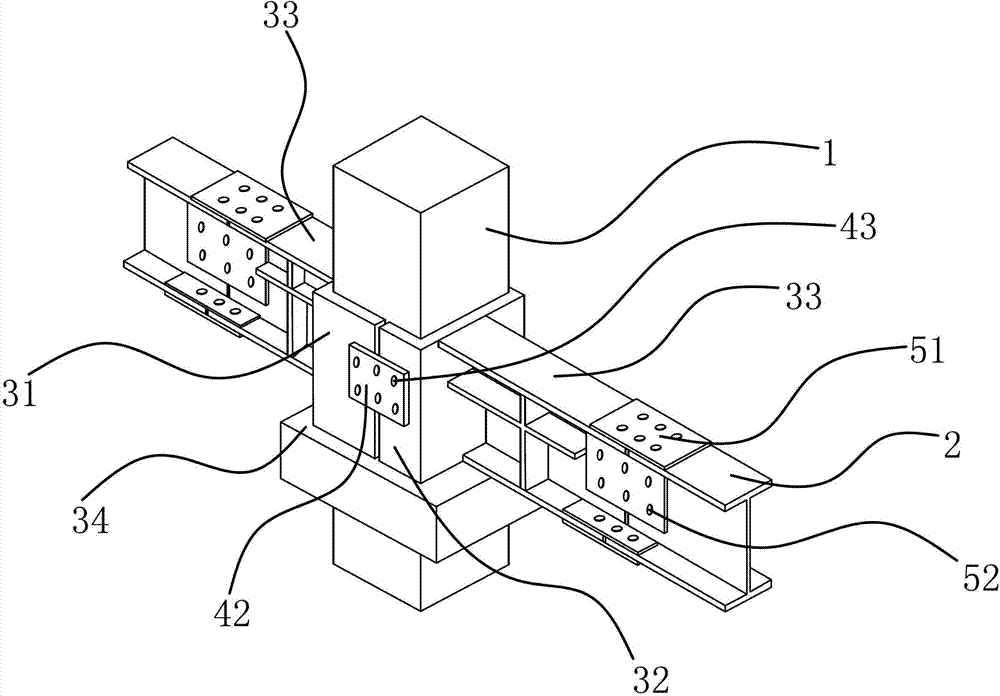
图1是实施例一中本连接节点、混凝土柱和钢梁三者的连接结构示意图。Fig. 1 is a schematic diagram of the connection structure of the connection node, the concrete column and the steel beam in the first embodiment.
图2是实施例一中本连接节点双连接臂与钢梁的连接结构示意图。Fig. 2 is a schematic diagram of the connection structure between the double connection arm of the connection node and the steel beam in the first embodiment.
图3是实施例一中本连接节点单连接臂与钢梁的连接结构示意图。Fig. 3 is a schematic diagram of the connection structure between the single connecting arm of the connection node and the steel beam in the first embodiment.
图4是实施例一中混凝土柱上凸肩的另一种结构示意图。Fig. 4 is another structural schematic diagram of the shoulder on the concrete column in the first embodiment.
图5是实施例一中本连接节点的截面图。Fig. 5 is a cross-sectional view of the connecting node in the first embodiment.
图6是实施例二中连接板一与半钢套一和半钢套二的另一种连接结构示意图。Fig. 6 is a schematic diagram of another connection structure between the first connecting plate and the first half steel sleeve and the second half steel sleeve in the second embodiment.
图7是实施例一中连接板二与钢梁和连接臂的另一种连接结构示意图。Fig. 7 is a schematic diagram of another connection structure between the second connecting plate and the steel beam and the connecting arm in the first embodiment.
图中,1、混凝土柱;2、钢梁;31、半钢套一;32、半钢套二;33、连接臂;34、凸肩;41、连接孔;42、连接板一;43、连接螺栓一;51、连接板二;52、连接螺栓二;6、翻边;7、倾斜部;81、横向加强肋;82、纵向加强肋。In the figure, 1, concrete column; 2, steel beam; 31, half-steel sleeve one; 32, half-steel sleeve two; 33, connecting arm; 34, raised shoulder; 41, connecting hole; 42, connecting plate one; 43, Connecting bolt one; 51, connecting plate two; 52, connecting bolt two; 6, flanging; 7, inclined part; 81, transverse reinforcing rib; 82, longitudinal reinforcing rib.
具体实施方式Detailed ways
以下是本实用新型的具体实施例并结合附图,对本实用新型的技术方案作进一步的描述,但本实用新型并不限于这些实施例。The following are specific embodiments of the utility model and in conjunction with the accompanying drawings, the technical solution of the utility model is further described, but the utility model is not limited to these embodiments.
实施例一:Embodiment one:
如图1、图2、图3和图5所示,一种混凝土柱与钢梁的连接节点,包括混凝土柱1和钢梁2,本节点包括半钢套一31和半钢套二32,半钢套一31和半钢套二32可拆卸连接且连接后能够套设在混凝土柱1上;半钢套一31和/或半钢套二32上焊接固连有连接臂33,半钢套一31和半钢套二32与连接臂33之间采用双面角焊缝的方式固连,连接臂33与钢梁2可拆卸连接;混凝土柱1上设置有凸肩34,半钢套一31和半钢套二32能够抵靠在凸肩34上,半钢套一31和半钢套二32上均开设有连接孔41,本连接节点还包括若干块连接板一42和若干根能够插设在连接孔41内的连接螺栓一43,连接板一42的两端通过连接螺栓一43分别与半钢套一31和半钢套二32连接,在安装半钢套一31和半钢套二32时,将半钢套一31和半钢套二32扣置在混凝土柱1上,根据半钢套一31和半钢套二32上的连接孔41的位置,在连接板一42上冲压出与之对应的通孔,然后通过连接螺栓一43将半钢套一31和半钢套二32固连,可以看出,这样的连接方式和施工方法,能够尽可能的减小钢套与混凝土柱1之间的配合间隙,防止钢套与混凝土柱1之间发生松动。As shown in Figure 1, Figure 2, Figure 3 and Figure 5, a connection node between a concrete column and a steel beam includes a
考虑到混凝土柱1与钢梁2之间的连接节点一般处于外露状态,受到空气等物质的腐蚀较严重,为了保证连接节点以及整个支撑结构的强度,采用半钢套一31和半钢套二32拼接的方式实现钢套与混凝土柱1的套置,而且还可以适当的根据混凝土柱1的尺寸来调整半钢套一31和半钢套二32的尺寸,从而减小钢套与混凝土柱1之间的配合间隙,提高节点的精度,也降低了施工难度;而本方案中,由于钢梁2与连接臂33之间采用多块连接板可拆卸连接方式相互连接,一方面可以大大降低施工难度,而且,在发现钢梁2与节点之间的连接部件发生较为严重的腐蚀或破坏时,还可以通过更换相关连接部件来修复,及时的消除安全隐患;为了不破坏混凝土柱1原有的强度、不改变混凝土柱1内部本身的结构,在浇注混凝土柱1时,同时浇注出一个与混凝土柱1一体的凸肩34,该凸肩34可以是单边或对边伸出混凝土柱1外缘的牛腿,半钢套一31和半钢套二32的下端抵靠在凸肩34上,对半钢套一31和半钢套二32进行支撑;当然,凸肩34内也浇注有加强凸肩34强度和刚度的钢筋或钢板等,不难看出:本方案中钢梁2对钢套的作用力除部分分解为对混凝土柱1的剪切力外,大部分由凸肩34来承受,由于对凸肩34的作用力是均衡的分布在凸肩34的四周的,而且受力方向为混凝土柱1的竖直方向,可以避免连接节点对混凝土柱1的局部压力导致混凝土柱1产生裂缝、变形,甚至破坏的可能,充分的体现了建筑设计中“强柱弱梁”的要求;在梁柱节点处,钢套除满足钢梁2的连接要求外,对内部混凝土也有限制其横向变形的作用,提高混凝土的强度,满足结构设计“强节点弱构件”的要求。Considering that the connection nodes between the
连接臂33的外端与钢梁2之间设置有连接板二51,连接板二51的两端分别通过若干根连接螺栓二52与连接臂33和钢梁2相连。先安装连接节点,后安装钢梁2,可以根据改变连接板二51上的通孔的位置,来消除钢梁2预设长度裁剪时的误差和安装的误差,从而提高安装精度和安装质量,也是提高连接节点强度和安全性能的做法,在实际实施过程中,如图7所示,连接臂33和钢梁2与连接板二51的连接方式还可以是:连接臂33的外端焊接有连接板二51,连接板二51与钢梁2之间通过若干根连接螺栓二52相连,安装钢梁2时,先通过连接螺栓二52将钢梁2与连接板二51固连,然后,将连接板二51焊接在连接臂33的外端,其施工简单,而且误差较小,不会存在由于安装给钢梁2和连接臂33带来额外应力的问题。A connecting
作为优选,半钢套一31和半钢套二32的下端设置有翻边6,翻边6的上端与钢梁2下端相抵靠,翻边6的下端与凸肩34上端相抵靠。在半钢套一31和半钢套二32的下端设置翻边6,可以减小凸肩34承受的压强,从而减小凸肩34强度上的要求。Preferably, the lower ends of the first
如图4所示,作为优选,凸肩34的下端与混凝土柱1之间设置有一个倾斜部7,对凸肩34的受力状况进一步的优化。As shown in FIG. 4 , preferably, an
钢梁2为工字梁和连接臂33均为工字梁,连接臂33的腹板与半钢套一31或半钢套二32之间焊接有横向加强肋81,连接臂33的两个翼板之间焊接有纵向加强肋82,横向加强肋81和纵向加强肋82大大加强了连接臂33的强度,提高了本连接节点的可靠度;而且,横向加强肋81还可以与连接板二51相抵靠,并焊接在一起,使钢梁2与连接臂33的连接强度也得到加强。The
实施例二:Embodiment two:
如图6所示,本实施例的内容大致与实施例一相同,所不同的是:半钢套一31上固设有若干块连接板一42,连接板一42通过若干根连接螺栓一43与半钢套二32相连,为了更好的较小施工难度和提高安装精确度,连接板一42的一端可以采用与半钢套一31焊接方式,另一端与半钢套二32采用连接螺栓一43固连,与上一种方案不同的是,连接板一42上的通孔可以提前开设,先将连接板的一端通过连接螺栓一43与半钢套二32固连后,再将另一端与半钢套一31焊接,其施工更加简易。As shown in Figure 6, the content of this embodiment is roughly the same as that of
本文中所描述的具体实施例仅仅是对本实用新型精神作举例说明。本实用新型所属技术领域的技术人员可以对所描述的具体实施例做各种各样的修改或补充或采用类似的方式替代,但并不会偏离本实用新型的精神或者超越所附权利要求书所定义的范围。The specific embodiments described herein are only examples to illustrate the spirit of the present invention. Those skilled in the technical field to which the utility model belongs can make various modifications or supplements to the described specific embodiments or adopt similar methods to replace them, but they will not deviate from the spirit of the utility model or go beyond the appended claims defined range.
尽管本文较多地使用了混凝土柱1、钢梁2、半钢套一31、半钢套二32、连接臂33、凸肩34、连接孔41、连接板一42、连接螺栓一43、连接板二51、连接螺栓二52、翻边6、倾斜部7、横向加强肋81、纵向加强肋82等术语,但并不排除使用其它术语的可能性。使用这些术语仅仅是为了更方便地描述和解释本实用新型的本质;把它们解释成任何一种附加的限制都是与本实用新型精神相违背的。Although this article uses more
Claims (8)
Priority Applications (1)
| Application Number | Priority Date | Filing Date | Title |
|---|---|---|---|
| CN 201320254491 CN203247717U (en) | 2013-05-10 | 2013-05-10 | Connecting node of concrete column and steel beam |
Applications Claiming Priority (1)
| Application Number | Priority Date | Filing Date | Title |
|---|---|---|---|
| CN 201320254491 CN203247717U (en) | 2013-05-10 | 2013-05-10 | Connecting node of concrete column and steel beam |
Publications (1)
| Publication Number | Publication Date |
|---|---|
| CN203247717U true CN203247717U (en) | 2013-10-23 |
Family
ID=49374164
Family Applications (1)
| Application Number | Title | Priority Date | Filing Date |
|---|---|---|---|
| CN 201320254491 Expired - Fee Related CN203247717U (en) | 2013-05-10 | 2013-05-10 | Connecting node of concrete column and steel beam |
Country Status (1)
| Country | Link |
|---|---|
| CN (1) | CN203247717U (en) |
Cited By (5)
| Publication number | Priority date | Publication date | Assignee | Title |
|---|---|---|---|---|
| CN103243818A (en) * | 2013-05-10 | 2013-08-14 | 汪洋 | Connection joint of concrete column and steel beam |
| CN103669571A (en) * | 2013-12-19 | 2014-03-26 | 上海都市绿色工程有限公司 | Wall beam fixing structure for greenhouse |
| CN104612252A (en) * | 2015-01-12 | 2015-05-13 | 金陵科技学院 | Beam and column connecting structure of portable house |
| CN106638945A (en) * | 2016-11-22 | 2017-05-10 | 浙江东南网架股份有限公司 | Six-rod-tetrahedral-module-unit assembled cover-plate-and-bolt-connected sphere joint and assembling method thereof |
| CN113622518A (en) * | 2021-03-09 | 2021-11-09 | 中船第九设计研究院工程有限公司 | Main beam anti-slip connection structure suitable for large-temperature deformation roof |
-
2013
- 2013-05-10 CN CN 201320254491 patent/CN203247717U/en not_active Expired - Fee Related
Cited By (8)
| Publication number | Priority date | Publication date | Assignee | Title |
|---|---|---|---|---|
| CN103243818A (en) * | 2013-05-10 | 2013-08-14 | 汪洋 | Connection joint of concrete column and steel beam |
| CN103243818B (en) * | 2013-05-10 | 2015-12-09 | 汪洋 | The connected node of a kind of concrete column and girder steel |
| CN103669571A (en) * | 2013-12-19 | 2014-03-26 | 上海都市绿色工程有限公司 | Wall beam fixing structure for greenhouse |
| CN103669571B (en) * | 2013-12-19 | 2016-02-17 | 上海都市绿色工程有限公司 | A kind of greenhouse wall beam fixed structure |
| CN104612252A (en) * | 2015-01-12 | 2015-05-13 | 金陵科技学院 | Beam and column connecting structure of portable house |
| CN104612252B (en) * | 2015-01-12 | 2017-01-18 | 金陵科技学院 | Beam and column connecting structure of portable house |
| CN106638945A (en) * | 2016-11-22 | 2017-05-10 | 浙江东南网架股份有限公司 | Six-rod-tetrahedral-module-unit assembled cover-plate-and-bolt-connected sphere joint and assembling method thereof |
| CN113622518A (en) * | 2021-03-09 | 2021-11-09 | 中船第九设计研究院工程有限公司 | Main beam anti-slip connection structure suitable for large-temperature deformation roof |
Similar Documents
| Publication | Publication Date | Title |
|---|---|---|
| CN103243818B (en) | The connected node of a kind of concrete column and girder steel | |
| CN203878780U (en) | Connecting joint of cylindrical rib penetrating type steel pipe concrete column and steel beam | |
| CN104032864B (en) | The web perforate H section steel connecting node that buckling-restrained steel plate wall is connected with concrete frame | |
| CN212582889U (en) | Splicing reinforced building beam column joint connecting structure | |
| CN108589918A (en) | A kind of connection structure of assembling truss beam and quadrate steel pipe column | |
| CN103174222A (en) | Steel casting modularization panel point for connection of steel pipe column and H-shaped beam | |
| CN104583496A (en) | Truss element method without chord members and combined node bridge | |
| CN104196152B (en) | Connecting structure for steel coupling beam and concrete wall | |
| CN105088971B (en) | Mid-span closure construction method of corrugated steel web PC box girder cable-stayed bridge | |
| CN204753819U (en) | Take tree -like supporting grid structure of secondary branching of prestressing force | |
| CN216428562U (en) | An assembled beam-column weak-axis connection node | |
| CN203891214U (en) | Dog bone type section steel connection node for precast concrete frame | |
| CN107419916B (en) | Internal moment reinforcing and correcting device for beam structure | |
| CN205046459U (en) | Derive formula member reinforced structure and have its steel longeron of steel longeron | |
| CN114016608A (en) | A prefabricated beam-column strong shaft connection node and its construction method | |
| CN222227059U (en) | Combined section steel anchor beam | |
| CN204940144U (en) | A kind of Wavelike steel webplate temporary reinforcing device | |
| CN205295915U (en) | Wave form steel web nose girder | |
| CN102425269A (en) | Large plate girder capable of suspending heavy object and construction method thereof | |
| CN102644327A (en) | Panel binding type connection node of concrete filled steel tube laminated column and steel beam and construction method | |
| CN102392491A (en) | Connecting joint for beam, column and inclined strut of box section of boiler steel frame and construction method thereof | |
| CN109518588A (en) | A new type of plate-truss composite beam and its construction method | |
| CN216428561U (en) | An assembled beam-column strong shaft connection node | |
| CN113235755B (en) | Y-shaped eccentric support energy consumption structure, assembled support frame system and construction method | |
| CN116480010A (en) | A prefabricated timber structure node embedded with steel components |
Legal Events
| Date | Code | Title | Description |
|---|---|---|---|
| C14 | Grant of patent or utility model | ||
| GR01 | Patent grant | ||
| CF01 | Termination of patent right due to non-payment of annual fee |
Granted publication date: 20131023 Termination date: 20150510 |
|
| EXPY | Termination of patent right or utility model |