CN203187107U - Logistic tray stacking bracket - Google Patents
Logistic tray stacking bracket Download PDFInfo
- Publication number
- CN203187107U CN203187107U CN 201320255581 CN201320255581U CN203187107U CN 203187107 U CN203187107 U CN 203187107U CN 201320255581 CN201320255581 CN 201320255581 CN 201320255581 U CN201320255581 U CN 201320255581U CN 203187107 U CN203187107 U CN 203187107U
- Authority
- CN
- China
- Prior art keywords
- chute
- contact switch
- slide block
- switch
- drive motor
- Prior art date
- Legal status (The legal status is an assumption and is not a legal conclusion. Google has not performed a legal analysis and makes no representation as to the accuracy of the status listed.)
- Withdrawn - After Issue
Links
Images


Landscapes
- De-Stacking Of Articles (AREA)
Abstract
The utility model discloses a logistic tray stacking bracket. The logistic tray stacking bracket comprises a bracket main body, a lifting device and a control device; the bracket main body comprises a square top supporting platform and four upright posts; the upright posts are arranged at the four corners of the square top supporting platform; a sliding groove is vertically formed in the bottom of each upright post; a sliding block is arranged in each sliding groove; the lifting device comprises a drive motor, guide wheels and steel ropes; the drive motor is arranged on the upper part of the square top supporting platform; the guide wheels are arranged at the top ends of the upright posts; one ends of the steel ropes are fixedly connected with the sliding blocks in the sliding grooves; the other ends of the steel ropes are wound around the drive shaft of the drive motor; the control device comprises an upper contact switch, a lower contact switch, an upper infrared photoelectric switch, a bottom infrared photoelectric switch and a lift controller; and the drive motor, the upper contact switch, the lower contact switch, the upper infrared photoelectric switch and the bottom infrared photoelectric switch are all connected with the lift controller. The logistic tray stacking bracket has the advantages that trays are withdrawn and used from the bottom, so that the time and labor are saved; the trays are prevented from damage; and potential safety risks are avoided.
Description
Technical field:
The utility model relates to a kind of logistics tray and piles up support, belongs to the logistics transportation device.
Background technology:
Often use the pallet bearing goods to transport at the logistics transport field, pallet will be piled height and piles up when not using, and pallet is piled up and taken off, and all by manually carrying out, wastes time and energy, and increases cost of labor; When pallet takes off, because the weight of pallet self often causes the pallet damage, the service life of having reduced pallet; When pallet takes off, also the safety misadventure that pallet injures the workman by a crashing object can take place.
The utility model content:
The purpose of this utility model is to provide a kind of pallet that will pile up to put down automatically, and the convenient a kind of logistics tray that takes out is piled up support.
The utility model is implemented by following technical scheme: a kind of logistics tray is piled up support, it is characterized in that, it comprises rack body, bont and control setup, described rack body comprises square shaped top support platform and four root posts, and four jiaos bottom described square shaped top support platform are fixed with described column respectively; Vertically be provided with chute every described column bottom; On every described column, vertically be provided with the vertical through hole that is communicated with described chute; Sidewall at described chute notch is provided with guide plate; Be provided with position-limited lever in the described chute above described guide plate; Be provided with the slide block that slides up and down in the described chute below described position-limited lever; Described slide block one end places described chute outside, described slide block in described chute outside is fixed with vertical S. A., be provided with the hold-down arm that horizontally rotates at described S. A., be set with torsion spring at described S. A., described torsion spring one end is captiveed joint with described slide block, the described torsion spring other end is captiveed joint with described hold-down arm, described hold-down arm and described guide plate split wipe contact; Described bont comprises drive motor, track adjusting wheel and steel rope, is provided with described drive motor on described square shaped top support platform top; Be provided with described track adjusting wheel on every described column top; In every described vertical through hole, be provided with steel cable, described slide block captive joint in described steel rope one end and the corresponding described chute of described vertical through hole, described steel rope middle part is overlapped on the corresponding described track adjusting wheel, the other end is wrapped on the axle drive shaft of described drive motor; Described control setup comprises contact switch, following contact switch, goes up Photoelectric infrared switch, bottom Photoelectric infrared switch and lifting controller; Be provided with contact switch at described position-limited lever; Be provided with contact switch down in the bottom of described chute; Be provided with Photoelectric infrared switch at the sidewall of described column; Sidewall in described column bottom is provided with the bottom Photoelectric infrared switch; Described lifting controller places the top of described square shaped top support platform; Described drive motor, describedly go up contact switch, described contact switch down, the described Photoelectric infrared switch of going up all is connected with described lifting controller with, described bottom Photoelectric infrared switch.
Described bont comprises air pump, air cylinder, be provided with described air pump on described square shaped top support platform top, be fixed with described air cylinder in the described chute on every described column, captive joint with described slide block in the piston rod top of described air cylinder, described air cylinder is connected with described air pump respectively, and the pipeline of connection places in the corresponding described vertical through hole.
Described air pump is Hydraulic Pump; Described air cylinder is hydraulic actuating cylinder.
Advantage of the present utility model: put in order and pile up neatly the pallet realization from bottom extraction use, time saving and energy saving, avoided reaching potential safety hazard because manually take off the pallet damage that pallet causes from the top; Save manpower, reduce cost of labor; Improve pallet service life; Device structure is simple, be convenient to safeguard, just have market outlook widely.
Description of drawings:
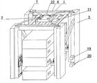
Fig. 1 is the overall schematic of embodiment 1.
Fig. 2 is the pillar construction scheme drawing of embodiment 1.
Fig. 3 puts into view for the pallet of embodiment 1.
Fig. 4 is the readiness for action scheme drawing of embodiment 1.
Fig. 5 is the overall schematic of embodiment 2.
Fig. 6 is the pillar construction scheme drawing of embodiment 2.
Fig. 7 puts into view for the pallet of embodiment 2.
Fig. 8 is the readiness for action scheme drawing of embodiment 2.
Fig. 9 is the overall schematic of embodiment 3.
Figure 10 is the pillar construction scheme drawing of embodiment 3.
The specific embodiment:
Embodiment 1: as shown in Figure 1 to Figure 3, a kind of logistics tray is piled up support, and it comprises rack body 1, bont 2 and control setup 3; Rack body 1 comprises square shaped top support platform 4 and four root posts 5, is fixed with column 5 respectively at square shaped top support platform 4 four jiaos; Vertically be provided with chute 6 in every root post 5 bottoms; On every root post 5, vertically be provided with the vertical through hole 7 that is communicated with chute 6; Sidewall at chute 6 notches is provided with guide plate 8; Be provided with position-limited lever 9 in the chute 6 above guide plate 8; Be provided with the slide block 10 that slides up and down in the chute 6 below position-limited lever 9, slide block 10 1 ends place chute 6 outsides, and the slide block 10 in chute 6 outsides is fixed with vertical S. A. 11, are provided with the hold-down arm 12 that horizontally rotates at S. A. 11; Be set with torsion spring 13 at S. A. 11, torsion spring 13 1 ends are captiveed joint with slide block 10, and torsion spring 13 other ends are captiveed joint with hold-down arm 12, hold-down arm 12 and guide plate 8 split wipe contacts; Bont 2 comprises drive motor 14, track adjusting wheel 15 and steel rope 16; Be provided with drive motor 14 on square shaped top support platform 4 tops; Be provided with track adjusting wheel 15 on every root post 5 tops; In every vertical through hole 7, be provided with steel cable 16, slide block 10 captive joints in steel rope 16 1 ends and the vertical through hole 7 corresponding chutes 6, steel rope 16 middle parts are overlapped on the corresponding track adjusting wheel 15, the other end is wrapped on the axle drive shaft of drive motor 14; Control setup 3 comprises contact switch 17, following contact switch 18, goes up Photoelectric infrared switch 19, bottom Photoelectric infrared switch 20 and lifting controller 21; Be provided with contact switch 17 at position-limited lever 9; Be provided with contact switch 18 down in the bottom of chute 6; Be provided with Photoelectric infrared switch 19 at the sidewall of column 5; Sidewall in column 5 bottoms is provided with bottom Photoelectric infrared switch 20; Lifting controller 21 places the top of square shaped top support platform 4; Drive motor 14, last contact switch 17, following contact switch 18, last Photoelectric infrared switch 19 and bottom infrared light are established 20 passes by cable and all are connected with lifting controller 21.
Working process: the whole buttress pallet that will pile up is pushed in the middle of four root posts 5, after last Photoelectric infrared switch 19 and bottom Photoelectric infrared switch 20 shine pallet, send signal to lifting controller 21,14 work of lifting controller 21 control drive motor, with slide block 10 pull-up straight up that is pressed in down on the contact switch 18, being pulled up to slide block 10 contacts with last contact switch 17, last contact switch 17 sends signal to lifting controller 21, lifting controller 21 control drive motor 14 quit work, and the state that keeps Locked, enter readiness for action; Each hold-down arm 12 and corresponding guide plate 8 wipe contacts in the process of pull-up, four hold-down arm 12 front ends horizontally rotate in the jack that extend into second pallet in bottom respectively, all pallets of second pallet and top are upwards held up, separate with the pallet of bottommost;
After readiness for action is extracted the pallet of bottommost out, Photoelectric infrared switch 20 irradiations in bottom are less than behind the pallet, the bottom infrared light establishes 20 by cable to lifting controller 21 transmission signals, 14 work of lifting controller 21 control drive motor, to put down straight down with the slide block 10 that last contact switch 17 contacts, being lowered into slide block 10 is pressed in down on the contact switch 18, following contact switch 18 sends signal to lifting controller 21,14 contrarotations of lifting controller 21 control drive motor, each hold-down arm 12 all is pressed on the hold-down arm 12 because of the weight of pallet in the process that slide block 10 puts down, hold-down arm 12 is inserted in the jack of pallet all the time, and after pallet landed, slide block 10 drives hold-down arm 12 to be continued to fall, hold-down arm 12 is with after pallet separates, under the effect of torsion spring 13, horizontally rotate withdrawal, be pressed in down on the contact switch 18 up to slide block 10;
Equipment repeats with the upwards action of picking-up of pallet, up to readiness for action; Repeat the action that pallet puts down, holds up, realization is put in order the buttress pallet and is extracted use from the bottom, has avoided reaching potential safety hazard because manually taking off the pallet damage that pallet causes;
When in equipment, having only a pallet, pallet is falling to the ground, slide block 10 puts down straight down, being lowered into slide block 10 is pressed in down on the contact switch 18, last Photoelectric infrared switch 19 irradiations are less than behind the pallet, and last Photoelectric infrared switch 19 sends signal to lifting controller 21, and lifting controller 21 control drive motor 14 quit work, make slide block 10 keep being pressed in down the state of contact switch 18, wait for that the whole buttress logistics tray of piling up pushes.
Embodiment 2: pile up support as Fig. 4 to a kind of logistics tray shown in Figure 6, it comprises rack body 1, bont 2 and control setup 3, bont 2 comprises air pump 22, air cylinder 23, be provided with air pump 22 on square shaped top support platform 4 tops, be fixed with air cylinder 23 in the chute 6 on every root post 5, pneumatic cylinder piston rod 24 stretches out downwards or the setting of withdrawing, captive joint with slide block 10 in pneumatic cylinder piston rod 24 tops, each air cylinder 23 is connected with air pump 22 respectively, and the pipeline of connection places in the corresponding vertical through hole 7; Other structure is identical with embodiment 1.
Working process: the whole buttress logistics tray that will pile up is pushed in the middle of four root posts 5, after last Photoelectric infrared switch 19 and bottom Photoelectric infrared switch 20 shine pallet, send signal to lifting controller 21,22 work of lifting controller 21 control air pumps, to be pressed in down slide block 10 pull-up straight up on the contact switch 18 by air cylinder 23, being pulled up to slide block 10 contacts with last contact switch 17, last contact switch 17 sends signal to lifting controller 21, lifting controller 21 control air pumps 22 quit work, and make air cylinder 23 state that keeps Locked, enter readiness for action; Each hold-down arm 12 and corresponding guide plate 8 wipe contacts in the process of pull-up, four hold-down arm 12 front ends horizontally rotate in the jack that extend into second pallet in bottom respectively, all pallets of second pallet and top are upwards held up, separate with the pallet of bottommost;
After readiness for action is extracted the pallet of bottommost out, Photoelectric infrared switch 20 irradiations in bottom are less than behind the pallet, the bottom infrared light establishes 20 by cable to lifting controller 21 transmission signals, 22 work of lifting controller 21 control air pumps, to put down straight down with the slide block 10 that last contact switch 17 contacts by air cylinder 23, be lowered into slide block 10 and be pressed in down on the contact switch 18, following contact switch 18 sends signal to lifting controller 21, and lifting controller 21 control air pumps 22 promote; Each hold-down arm 12 all is pressed on the hold-down arm 12 because of the weight of pallet in the process that slide block 10 puts down, hold-down arm 12 is inserted in the jack of pallet all the time, after pallet lands, slide block 10 drives hold-down arm 12 to be continued to fall, hold-down arm 12 is with after pallet separates, under the effect of torsion spring 13, horizontally rotate withdrawal, be pressed in down on the contact switch 18 up to slide block 10;
Equipment repeats with the upwards action of picking-up of second pallet in bottom, up to readiness for action; Repeat the action that pallet puts down, holds up, realization is put in order the buttress pallet and is extracted use from the bottom, has avoided reaching potential safety hazard because manually taking off the pallet damage that pallet causes;
When in equipment, having only a pallet, pallet is falling to the ground, slide block 10 puts down straight down, be lowered into slide block 10 and be pressed in down on the contact switch 18, last Photoelectric infrared switch 19 irradiations are less than behind the pallet, and last Photoelectric infrared switch 19 sends signal to lifting controller 21, lifting controller 21 control air pumps 22 quit work, make slide block 10 keep being pressed in down the state of contact switch 18 by air cylinder 23, wait for that the whole buttress logistics tray of piling up pushes, and works on.
Embodiment 3: a kind of logistics tray is piled up support as shown in Figure 7 and Figure 8, it comprises rack body 1, bont 2, control setup 3, bont 2 comprises Hydraulic Pump 25, hydraulic actuating cylinder 26, be provided with Hydraulic Pump 25 on square shaped top support platform 4 tops, be fixed with gas-hydraulic cylinder 26 in the chute 6 on every root post 5, hydraulic cylinder piston rod 27 stretches out downwards or the setting of withdrawing, captive joint with slide block 10 in hydraulic cylinder piston rod 27 tops, each hydraulic actuating cylinder 26 is connected with Hydraulic Pump 25 respectively, and the pipeline of connection places in the corresponding vertical through hole 7; Other structure is identical with embodiment 2.
Working process is identical with embodiment 2.
Claims (3)
1. a logistics tray is piled up support, it is characterized in that, it comprises rack body, bont and control setup; Described rack body comprises square shaped top support platform and four root posts, is fixed with described column respectively at described square shaped top support platform four jiaos; Vertically be provided with chute every described column bottom; On every described column, vertically be provided with the vertical through hole that is communicated with described chute; Sidewall at described chute notch is provided with guide plate; Be provided with position-limited lever in the described chute above described guide plate; Be provided with the slide block that slides up and down in the described chute below described position-limited lever; Described slide block one end places described chute outside, and the described slide block in described chute outside is fixed with vertical S. A., is provided with the hold-down arm that horizontally rotates at described S. A.; Be set with torsion spring at described S. A., described torsion spring one end is captiveed joint with described slide block, and the described torsion spring other end is captiveed joint with described hold-down arm, described hold-down arm and described guide plate split wipe contact; Described bont comprises drive motor, track adjusting wheel and steel rope, is provided with described drive motor on described square shaped top support platform top; Be provided with described track adjusting wheel on every described column top; In every described vertical through hole, be provided with steel cable, described slide block captive joint in described steel rope one end and the corresponding described chute of described vertical through hole, described steel rope middle part is overlapped on the corresponding described track adjusting wheel, the other end is wrapped on the axle drive shaft of described drive motor; Described control setup comprises contact switch, following contact switch, goes up Photoelectric infrared switch, bottom Photoelectric infrared switch and lifting controller; Be provided with contact switch at described position-limited lever; Be provided with contact switch down in the bottom of described chute; Be provided with Photoelectric infrared switch at the sidewall of described column; Sidewall in described column bottom is provided with the bottom Photoelectric infrared switch; Described lifting controller places the top of described square shaped top support platform; Described drive motor, describedly go up contact switch, described contact switch down, the described Photoelectric infrared switch of going up all is connected with described lifting controller with, described bottom Photoelectric infrared switch.
2. a kind of logistics tray according to claim 1 is piled up support, it is characterized in that,
Described bont comprises air pump, air cylinder, be provided with described air pump on described square shaped top support platform top, be fixed with described air cylinder in the described chute on every described column, captive joint with described slide block in the piston rod top of described air cylinder, described air cylinder is connected with described air pump respectively, and the pipeline of connection places in the corresponding described vertical through hole.
3. a kind of logistics tray according to claim 2 is piled up support, it is characterized in that, described air pump is Hydraulic Pump; Described air cylinder is hydraulic actuating cylinder.
Priority Applications (1)
| Application Number | Priority Date | Filing Date | Title |
|---|---|---|---|
| CN 201320255581 CN203187107U (en) | 2013-04-28 | 2013-04-28 | Logistic tray stacking bracket |
Applications Claiming Priority (1)
| Application Number | Priority Date | Filing Date | Title |
|---|---|---|---|
| CN 201320255581 CN203187107U (en) | 2013-04-28 | 2013-04-28 | Logistic tray stacking bracket |
Publications (1)
| Publication Number | Publication Date |
|---|---|
| CN203187107U true CN203187107U (en) | 2013-09-11 |
Family
ID=49103985
Family Applications (1)
| Application Number | Title | Priority Date | Filing Date |
|---|---|---|---|
| CN 201320255581 Withdrawn - After Issue CN203187107U (en) | 2013-04-28 | 2013-04-28 | Logistic tray stacking bracket |
Country Status (1)
| Country | Link |
|---|---|
| CN (1) | CN203187107U (en) |
Cited By (3)
| Publication number | Priority date | Publication date | Assignee | Title |
|---|---|---|---|---|
| CN103253518A (en) * | 2013-04-28 | 2013-08-21 | 内蒙古自治区烟草公司呼和浩特市公司 | Physical distribution tray stacking support |
| CN103552848A (en) * | 2013-11-09 | 2014-02-05 | 山西东杰智能物流装备股份有限公司 | Self-weight turnover plate tray-disassembling and stacking machine |
| CN106348003A (en) * | 2016-10-17 | 2017-01-25 | 江苏凯宫机械股份有限公司 | Intelligent material picking and releasing device of combing machine |
-
2013
- 2013-04-28 CN CN 201320255581 patent/CN203187107U/en not_active Withdrawn - After Issue
Cited By (5)
| Publication number | Priority date | Publication date | Assignee | Title |
|---|---|---|---|---|
| CN103253518A (en) * | 2013-04-28 | 2013-08-21 | 内蒙古自治区烟草公司呼和浩特市公司 | Physical distribution tray stacking support |
| CN103552848A (en) * | 2013-11-09 | 2014-02-05 | 山西东杰智能物流装备股份有限公司 | Self-weight turnover plate tray-disassembling and stacking machine |
| CN103552848B (en) * | 2013-11-09 | 2015-06-17 | 山西东杰智能物流装备股份有限公司 | Self-weight turnover plate tray-disassembling and stacking machine |
| CN106348003A (en) * | 2016-10-17 | 2017-01-25 | 江苏凯宫机械股份有限公司 | Intelligent material picking and releasing device of combing machine |
| CN106348003B (en) * | 2016-10-17 | 2023-09-08 | 江苏凯宫机械股份有限公司 | Intelligent combing machine material taking and placing device |
Similar Documents
| Publication | Publication Date | Title |
|---|---|---|
| CN103253518B (en) | Physical distribution tray stacking support | |
| CN202201684U (en) | Hydraulic fork truck and hydraulic fork truck with carrying device | |
| CN112110383A (en) | Double-upright-column stacking machine | |
| CN102514928A (en) | Automatic loading device of block machine supporting plates | |
| CN103288010B (en) | A kind of fork lift truck structure | |
| CN203187107U (en) | Logistic tray stacking bracket | |
| CN102417086A (en) | Automatic tray library | |
| CN102730422B (en) | Automatic pallet machine | |
| CN204474246U (en) | A kind of jacking system | |
| CN213595797U (en) | Double-upright-column stacking machine | |
| CN202880793U (en) | Movable type single column type aerial work platform | |
| CN203976291U (en) | Suspension type Copper Foil volume transport trolley | |
| CN102963715A (en) | Automatic vehicle loading device for steel drums | |
| CN202400631U (en) | Green brick piling machine | |
| CN202081681U (en) | Novel pit type parking device | |
| CN203461775U (en) | Large wine jar lifting device | |
| CN202609874U (en) | Concrete block finished product plate-curing type special conveying vehicle | |
| CN211224200U (en) | A conveyer for apple processing | |
| CN206126767U (en) | Freely promote two portal systems | |
| CN205011318U (en) | Formula storage battery frame is drawn to side | |
| CN201801121U (en) | Automatic pallet storeroom | |
| CN101935000A (en) | Tyre lifting device | |
| CN201660408U (en) | Tire lifting device | |
| CN203486849U (en) | Device for loading and unloading support trays | |
| CN202988235U (en) | Automatic steel drum loading device |
Legal Events
| Date | Code | Title | Description |
|---|---|---|---|
| C14 | Grant of patent or utility model | ||
| GR01 | Patent grant | ||
| AV01 | Patent right actively abandoned |
Granted publication date: 20130911 Effective date of abandoning: 20150603 |
|
| RGAV | Abandon patent right to avoid regrant |