CN203177290U - Vacuum tube solar energy and terrestrial heat complementation combined type heat supply system - Google Patents
Vacuum tube solar energy and terrestrial heat complementation combined type heat supply system Download PDFInfo
- Publication number
- CN203177290U CN203177290U CN2013200542684U CN201320054268U CN203177290U CN 203177290 U CN203177290 U CN 203177290U CN 2013200542684 U CN2013200542684 U CN 2013200542684U CN 201320054268 U CN201320054268 U CN 201320054268U CN 203177290 U CN203177290 U CN 203177290U
- Authority
- CN
- China
- Prior art keywords
- heat
- assembly
- water
- working medium
- pipe
- Prior art date
- Legal status (The legal status is an assumption and is not a legal conclusion. Google has not performed a legal analysis and makes no representation as to the accuracy of the status listed.)
- Expired - Fee Related
Links
Images


Classifications
-
- Y—GENERAL TAGGING OF NEW TECHNOLOGICAL DEVELOPMENTS; GENERAL TAGGING OF CROSS-SECTIONAL TECHNOLOGIES SPANNING OVER SEVERAL SECTIONS OF THE IPC; TECHNICAL SUBJECTS COVERED BY FORMER USPC CROSS-REFERENCE ART COLLECTIONS [XRACs] AND DIGESTS
- Y02—TECHNOLOGIES OR APPLICATIONS FOR MITIGATION OR ADAPTATION AGAINST CLIMATE CHANGE
- Y02B—CLIMATE CHANGE MITIGATION TECHNOLOGIES RELATED TO BUILDINGS, e.g. HOUSING, HOUSE APPLIANCES OR RELATED END-USER APPLICATIONS
- Y02B10/00—Integration of renewable energy sources in buildings
- Y02B10/20—Solar thermal
-
- Y—GENERAL TAGGING OF NEW TECHNOLOGICAL DEVELOPMENTS; GENERAL TAGGING OF CROSS-SECTIONAL TECHNOLOGIES SPANNING OVER SEVERAL SECTIONS OF THE IPC; TECHNICAL SUBJECTS COVERED BY FORMER USPC CROSS-REFERENCE ART COLLECTIONS [XRACs] AND DIGESTS
- Y02—TECHNOLOGIES OR APPLICATIONS FOR MITIGATION OR ADAPTATION AGAINST CLIMATE CHANGE
- Y02B—CLIMATE CHANGE MITIGATION TECHNOLOGIES RELATED TO BUILDINGS, e.g. HOUSING, HOUSE APPLIANCES OR RELATED END-USER APPLICATIONS
- Y02B10/00—Integration of renewable energy sources in buildings
- Y02B10/70—Hybrid systems, e.g. uninterruptible or back-up power supplies integrating renewable energies
-
- Y—GENERAL TAGGING OF NEW TECHNOLOGICAL DEVELOPMENTS; GENERAL TAGGING OF CROSS-SECTIONAL TECHNOLOGIES SPANNING OVER SEVERAL SECTIONS OF THE IPC; TECHNICAL SUBJECTS COVERED BY FORMER USPC CROSS-REFERENCE ART COLLECTIONS [XRACs] AND DIGESTS
- Y02—TECHNOLOGIES OR APPLICATIONS FOR MITIGATION OR ADAPTATION AGAINST CLIMATE CHANGE
- Y02B—CLIMATE CHANGE MITIGATION TECHNOLOGIES RELATED TO BUILDINGS, e.g. HOUSING, HOUSE APPLIANCES OR RELATED END-USER APPLICATIONS
- Y02B30/00—Energy efficient heating, ventilation or air conditioning [HVAC]
Landscapes
- Heat-Pump Type And Storage Water Heaters (AREA)
Abstract
The utility model discloses a vacuum tube solar energy and terrestrial heat complementation combined type heat supply system which comprises a heat preserving water tank assembly. The heat preserving water tank assembly comprises a water tank inner container. A water inlet tube head and a water outlet tube head are arranged on the lower portion of the water tank inner container and the upper portion of the water tank inner container respectively. A solar coil tube connected with a vacuum tube solar assembly, a heating coil tube connected with a heating loop assembly and a terrestrial source coil tube connected with a terrestrial heat source heat pump assembly are sequentially arranged in the water tank inner container from top to bottom. The water outlet tube head is connected with a water using tail end. A hot water collector is used for collecting used hot water flowing out through the water using tail end and delivering the used hot water to a waste heat exchanging device. A water inlet tube penetrates through the waste heat exchanging device and is connected to the water inlet tube head. The vacuum tube solar assembly, the heating loop assembly and the terrestrial heat source heat pump assembly are respectively and electrically connected with a controller assembly. Vacuum tube solar energy and a terrestrial heat source heat pump are complementary in use, waste heat is recycled, and therefore an energy use rate and unit energy efficiency are improved.
Description
Technical field
The utility model relates to the heat supply heating system of energy mix heating, relates in particular to a kind of vacuum pipe solar and underground heat complementary combinations formula heating system.
Background technology
Traditional storage-type and Instant heating type hot water apparatus be generally all by the single source heat supply, as: electric energy, combustion gas, solar energy, air source, water source, geothermal source etc.Owing to be subjected to the restriction of single source, following defective can occur: 1, when device breaks down, often the heat supply heating will be interrupted, and can't guarantee normal instructions for use; 2, be subjected to the restriction of service condition easily, as: the use safety problem of combustion gas, solar energy is in overcast and rainy use etc.; The capital produces certain restriction to the use of hot water apparatus; 3, do not satisfy many-sided heating heat supply requirement, as the place of needs heating simultaneously, heating and heat supply water; 4, single source heating heat supply does not meet the environmental protection and energy saving requirement that country advocates; 5, the hot water of people's use, after using, namely drain (no matter being bathing or other purposes), it is special when environment temperature is low, this secondary water of draining, though temperature not high (20 ~ 30 ℃), relative running water (winter is below 10 ℃), the heat that wherein contains is recycled easily.But the water of main flow custom is not used at present, wastes the utilizable energy source.
The utility model content
At defective and the deficiency of above-mentioned existence, a kind of vacuum pipe solar and underground heat complementary combinations formula heating system are proposed.
For solving the problems of the technologies described above, the technical scheme that the utility model adopts is: a kind of vacuum pipe solar and underground heat complementary combinations formula heating system are provided, comprise attemperater assembly, vacuum pipe solar assembly, heating loop assembly, earth source heat pump assembly, control assembly, inlet pipeline, water end, hot water gatherer and waste heat switch; Described attemperater assembly comprises inner water tank, inner water tank bottom and top are respectively equipped with into water tube head and water outlet tube head, and inner water tank inside is disposed with solar energy coil pipe, heating coil and ground source tray pipe from top to bottom between water outlet tube head and water inlet tube head; Described solar energy coil pipe connects described vacuum pipe solar assembly, and described heating coil connects described heating loop assembly, and described ground source tray pipe connects described earth source heat pump assembly; Described water outlet tube head connects described water end, and described hot water gatherer be used for to be collected from water is terminal and flowed out the hot water after using and it is delivered to described waste heat switch, and described inlet pipeline passes described waste heat switch and is connected to described water inlet tube head; Described vacuum pipe solar assembly, heating loop assembly, earth source heat pump assembly all are electrically connected described control assembly.
Wherein, described vacuum pipe solar assembly comprises vacuum heat collection pipe and circulating pump; Be provided with the working medium circulation line that flows for heat-transfer working medium in the described vacuum heat collection pipe, described working medium circulation line is connected by pipeline with solar energy coil pipe in the described attemperater assembly, and described circulating pump is set on connecting line; Described circulating pump is electrically connected described control assembly.
Wherein, the heat-transfer working medium in the described working medium circulation line is freezing liquid.
Wherein, described earth source heat pump assembly comprise earth source heat pump unit, ground source heat water-circulating pump, source cold water circulation pump, buried pipe network; Described earth source heat pump unit comprises first closed circuit of the confession flow of refrigerant that is made of compressor, condenser, throttling arrangement and evaporimeter; Described buried pipe network connects described evaporimeter by pipeline and constitutes second closed circuit that flows for first heat-transfer working medium, and to the cold-producing medium heating, source, described ground cold water circulation pump is arranged in this second closed circuit described first heat-transfer working medium in evaporimeter; Described ground source tray pipe connects described condenser by pipeline and constitutes the 3rd closed circuit that flows for second heat-transfer working medium, the heat of described second heat-transfer working medium absorption refrigeration agent in condenser also heats the water in the described inner water tank in ground source tray pipe, and described ground source heat water-circulating pump is arranged in the 3rd closed circuit; Described compressor, ground source heat water-circulating pump, the source cold water circulation pump all be electrically connected described control assembly.
Wherein, described first heat-transfer working medium and described second heat-transfer working medium are anti-icing fluid or water.
Wherein, described heating loop assembly comprise heating circulation pump, floor heating coil pipe or radiator, for detection of the temperature sensor of indoor temperature; Described floor heating coil pipe or radiator are connected by pipeline with heating coil in the described attemperater assembly, and described heating circulation pump is set on connecting line; Described heating circulation pump and described temperature sensor are electrically connected described control assembly.
Wherein, described inner water tank is enamel or stainless steel; Inner water tank is socketed with tank shell outward, is filled with insulation bubble material between tank shell and the inner water tank.
Wherein, on the described inlet pipeline safety valve is installed.
Wherein, described ground source tray pipe, solar energy coil pipe, heating coil material are gapless stainless steel tube or fin stainless steel tube.
The beneficial effects of the utility model are: 1, when one group of thermal source unit breaks down, can not influence normal heating heat demand; 2, this combined system adopts earth source heat pump and vacuum pipe solar to use as thermal source complementary, and according to its coil pipe position of each heat sources reasonable Arrangement, hydromining in the water tank is got the mode that segmentation is heated, also carry out waste heat recovery in addition, can improve the efficiency of rate of energy and unit; 3, meet the energy-conserving and environment-protective requirement that country advocates, use the high unit combination of energy utilization rate as far as possible.
Description of drawings
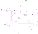
Fig. 1 is the structural representation of the utility model one embodiment;
Fig. 2 is the structural representation of attemperater assembly in the utility model;
Fig. 3 is the structural representation of earth source heat pump unit in the utility model.
Label declaration:
1, attemperater assembly; 11, water inlet tube head; 12, source tray pipe; 13, first temperature sensor; 14, heating coil; 15, solar energy coil pipe; 16, water outlet tube head; 17, tank upper cover; 18, inner water tank; 19, second temperature sensor; 101, insulation bubble material; 102, magnesium rod; 103, tank shell; 104, water tank lower cover; 105, water tank footing;
2, heating loop assembly; 21, floor heating coil pipe; 22, heating circulation pump; 23, three-temperature sensor;
3, vacuum pipe solar assembly; 31, working medium goes out house steward; 32, expansion drum; 33, air bleeding valve; 34, circulating pump; 35, the 4th temperature sensor; 36, vacuum heat collection pipe; 37, working medium is advanced house steward;
4, control assembly;
5, earth source heat pump assembly; 51, earth source heat pump unit; 52, ground source heat water-circulating pump; 53, source cold water circulation pump; 54, buried pipe network; 510, compressor; 511, condenser; 512, throttling arrangement; 513, evaporimeter;
6, inlet pipeline; 61, safety valve; 7, water end; 8, hot water gatherer; 9, waste heat switch.
The specific embodiment
By describing technology contents of the present utility model, structural feature in detail, realized purpose and effect, give explanation below in conjunction with embodiment and conjunction with figs. are detailed.
See also Fig. 1, present embodiment provides a kind of vacuum pipe solar and underground heat complementary combinations formula heating system, mainly comprises attemperater assembly 1, vacuum pipe solar assembly 3, heating loop assembly 2, earth source heat pump assembly 5, control assembly 4, inlet pipeline 6, water end 7, hot water gatherer 8 and waste heat switch 9.
As shown in Figure 2, attemperater assembly 1 comprises the housing that is made of inner water tank 18, tank shell 103, tank upper cover 17, water tank lower cover 104 and water tank footing 105, wherein tank shell 103 is socketed on outside the inner water tank 18, and is filled with insulation bubble material 101 between the two with 18 insulations of feed-tank inner bag.Inner water tank 18 is enamel or stainless steel, can high pressure resistant and corrosion.In order to prevent from corroding inner water tank 18, also be set with magnesium rod 102 on the inner water tank 18, magnesium rod 102 stretches to inner water tank 18 inside, prevents the inner water tank corrosion by principle of cathodic protection, reaches to prolong the water tank effect in service life.
Water outlet tube head 16 connects water end 7, hot water gatherer 8 arranges corresponding to water terminal 7, be used for to collect from water terminal 7 and flow out the hot water after using and it is delivered to waste heat switch 9, and inlet pipeline 6 passes the water inlet tube head 11 that waste heat switch 9 connects on the inner water tank 18, cold water can carry out preheating by the hot water that is recovered in the waste heat switch 9 before entering inner water tank 18 again, improve inflow temperature, when particularly winter, inflow temperature was low, effect was obvious.Because attemperater is press-bearing water tank, at inlet pipeline 6 safety valve 61 is installed, and plays the pressure release effect, prevents hypertonia in the water tank heating process.
Vacuum pipe solar assembly 3, heating loop assembly 2, earth source heat pump assembly 5 all are electrically connected control assembly 4.Control assembly 4 generally comprises controller mainboard, controller housing, holding wire etc., when work, mode by manual direct control button is sent instruction to control assembly 4, control assembly 4 is passed to the automatically controlled plate of corresponding assembly in the heating system with instruction, and automatically controlled plate is carried out corresponding control action and finished required function.In the present embodiment, inner water tank 18 bottoms are provided with first temperature sensor 13, top is provided with second temperature sensor 19, two sensors detects the water temperature on water tank bottom and top respectively, temperature value offers control assembly, and control assembly is relatively controlled the unlatching of earth source heat pump assembly and vacuum pipe solar assembly respectively by set pattern or closed according to corresponding water temperature and respective settings value.
This system combined operation principle is: in the time of solar light irradiation, can directly adopt the vacuum pipe solar assembly that the water in the water tank is heated, the earth source heat pump assembly then carries out preheating to the water of water tank, and this moment, the earth source heat pump assembly was done auxiliary heating use.During actual the use, utilize control assembly respectively solar energy heating assembly and earth source heat pump assembly to be controlled as required.For example: when shining upon, can start the earth source heat pump assembly in advance heats the water in the water tank, at this moment temperature can arrange lower, because can also utilize the vacuum pipe solar assembly that the water of water tank is heated, if run into overcast and rainy or evening the time, can directly utilize the earth source heat pump assembly that the water in the water tank is heated; By the heating coil in the water tank and heating circulation pump, also can heat to the room, realize the Combination application of heat supply heating.Simultaneously, utilize waste-heat recovery device, collect the secondary hot water, improve inflow temperature, reduce the power of whole heating heat supply, realize Combination application and the energy-saving effect of heat supply heating.
Adopt the advantage of such scheme to be: 1, when one group of thermal source unit breaks down, can not influence normal heating heat demand; 2, this combined system adopts earth source heat pump and vacuum pipe solar to use as thermal source complementary, and according to its coil pipe position of each heat sources reasonable Arrangement, hydromining in the water tank is got the mode that segmentation is heated, also carry out waste heat recovery in addition, can improve the efficiency of rate of energy and unit; 3, meet the energy-conserving and environment-protective requirement that country advocates, use the high unit combination of energy utilization rate as far as possible.
Introduce the structure of each thermal source and heating loop assembly more one by one below in conjunction with accompanying drawing.
Consult Fig. 1, the heating loop assembly 2 of present embodiment comprises floor heating coil pipe 21, heating circulation pump 22 and three-temperature sensor 23.Heating coil 14 in floor heating coil pipe 21 and the attemperater assembly 1 is connected by pipeline, and described heating circulation pump 22 is set on connecting line; Heating circulation pump 22 and three-temperature sensor 23 are electrically connected described control assembly 4.Three-temperature sensor 23 is for detection of indoor temperature, and when when control assembly 4 arranges heating mode, according to the heating temperature of indoor temperature and setting, heating circulation pump 22 optionally starts or closes, thereby the room is heated.Floor heating coil pipe 21 in the present embodiment can also replace with radiator, specifically chooses according to the heating demand.
Still consult Fig. 1, vacuum pipe solar assembly 3 mainly comprises vacuum heat collection pipe 36 and circulating pump 34, be provided with the working medium circulation line that flows for heat-transfer working medium in the vacuum heat collection pipe 36, wherein the import and export of working medium circulation line are connected with respectively that working medium is advanced house steward 37 and working medium goes out house steward 31, working medium is advanced house steward 37 and is gone out house steward 31 with working medium and be connected solar energy coil pipe 15 in the attemperater assembly 1 by pipeline respectively, thereby make working medium circulation line and solar energy coil pipe constitute the peripheral passage, circulating pump 34 is arranged in the connecting line, control assembly 4, the power that provides heat-transfer working medium to circulate are provided circulating pump 34.For the use safety of vacuum heat collection pipe 36, working medium goes out also to be connected with air bleeding valve 33 and expansion drum 32 on the house steward 31.This heating system generally is installed on roof (roof) with this vacuum pipe solar assembly 3 by bracing frame in use, makes solar energy be radiated at its interior heat-transfer working medium of heating on the vacuum heat collection pipe 36.
The operation principle of vacuum pipe solar assembly 3 is: solar irradiation raises its temperature the heating of the heat-transfer working medium in the working medium circulation line in the vacuum heat collection pipe 36 on vacuum heat collection pipe 36 gradually.In vacuum tube solar energy assembly 3 top working medium temperature T 1(present embodiments, this temperature is gathered by being arranged at the 4th temperature sensor 35 that working medium goes out on the house steward 31) gathered by first temperature sensor 13 with attemperater assembly 1 bottom water temperature T 2() the temperature difference when reaching certain value (generally being set at 3 ℃-5 ℃), circulating pump 34 starts, and heat-transfer working medium is circulated to the solar energy coil pipe 15 of attemperater assembly 1 and the water in the heat tracing water tank.When attemperater assembly 1 top water temperature T3(is gathered by second temperature sensor 19) when reaching setting value (generally being set at 50 ℃-60 ℃), circulating pump 34 quits work.Wherein, the 4th temperature sensor 35 is electrically connected control assemblies 4, and during use, the temperature that cooperates first temperature sensor 13 and second temperature sensor 19 to gather is by the unlatching of control assembly 4 control circulating pumps 34 or close.
Wherein, heat-transfer working medium can be freezing liquid or water, preferably, adopts freezing liquid, can solve antifreeze problem in winter.
Please consult Fig. 1 and Fig. 3 simultaneously, in the present embodiment, earth source heat pump assembly 5 comprise earth source heat pump unit 51, ground source heat water-circulating pump 52, source cold water circulation pump 53, buried pipe network 54.Earth source heat pump unit 51 comprises first closed circuit of the confession flow of refrigerant that is made of compressor 510, condenser 511, throttling arrangement 512 and evaporimeter 513; Wherein, respectively there are two streams condenser 511 and evaporimeter 513 inside, be respectively for the refrigerant flow path of described flow of refrigerant and the heat-transfer working medium stream that flows for heat-transfer working medium, separate between two streams, make cold-producing medium and heat-transfer working medium between two streams can carry out heat exchange but be separated with the heat conduction good metal.
Buried pipe network 54 constitutes second closed circuit that flows for first heat-transfer working medium by the heat-transfer working medium stream that pipeline connects evaporimeter 513, described first heat-transfer working medium heats cold-producing medium in evaporimeter 513, source, ground cold water circulation pump 53 is arranged in this second closed circuit, and the power of first heat-transfer working medium circulation is provided.
Ground source tray pipe 12 in the attemperater assembly 1 constitutes the 3rd closed circuit that flows for second heat-transfer working medium by the heat-transfer working medium stream that pipeline connects described condenser 511, the heat of described second heat-transfer working medium absorption refrigeration agent in condenser 511 also heats the water in the described inner water tank 18 in ground source tray pipe 12, described ground source heat water-circulating pump 52 is arranged in the 3rd closed circuit, and the power of second heat-transfer working medium circulation is provided.
The operation principle of this earth source heat pump assembly 5 is: compressor 510 starts, compression comes the low-temperature refrigerant gas of flash-pot 513, from 510 mouthfuls of gases of discharging HTHP of compressor, after condenser 511 heat releases, cold-producing medium becomes the liquid of temperature in the high pressure, passes through throttling arrangement 512 afterwards, and cold-producing medium becomes the liquid of low-temp low-pressure, thereby enter the gas that evaporimeter 513 heat absorptions become low-temp low-pressure, gas is sucked back by compressor 510 and finishes a circulation.Wherein, cold-producing medium absorbs heat in the evaporimeter 513 from first heat-transfer working medium, particularly, and by the operation of source, ground cold water circulation pump 53, first heat-transfer working medium in the buried pipe network 54 enters in the evaporimeter 513, absorbed heat by the cold-producing medium in the evaporimeter 513, first heat-transfer working medium low by the temperature after absorbing heat flows out from evaporimeter 513, and flows in buried pipe network 54 loops, the heat that absorption tube is outer, temperature constantly rises, and enters evaporimeter 513 at last again, constantly circulation.The heat of cold-producing medium then is used for the water of heat tracing water tank assembly 1 in the condenser 511, particularly, the cold-producing medium of HTHP is released into heat in second heat-transfer working medium at condenser 511, operation by ground source heat water-circulating pump 52, the second higher heat-transfer working medium of temperature enters the ground source tray pipe 12 that is arranged in attemperater assembly 1, with water heating in the attemperater assembly 1, then second heat-transfer working medium enters in the condenser 511 from cold-producing medium heat absorption, constantly circulation again.
First heat-transfer working medium and second heat-transfer working medium can be anti-icing fluid or water.
The above only is embodiment of the present utility model; be not so limit claim of the present utility model; every equivalent structure or equivalent flow process conversion that utilizes the utility model specification and accompanying drawing content to do; or directly or indirectly be used in other relevant technical fields, all in like manner be included in the scope of patent protection of the present utility model.
Claims (9)
1. a vacuum pipe solar and underground heat complementary combinations formula heating system, it is characterized in that, comprise attemperater assembly, vacuum pipe solar assembly, heating loop assembly, earth source heat pump assembly, control assembly, inlet pipeline, water end, hot water gatherer and waste heat switch;
Described attemperater assembly comprises inner water tank, inner water tank bottom and top are respectively equipped with into water tube head and water outlet tube head, and inner water tank inside is disposed with solar energy coil pipe, heating coil and ground source tray pipe from top to bottom between water outlet tube head and water inlet tube head; Described solar energy coil pipe connects described vacuum pipe solar assembly, and described heating coil connects described heating loop assembly, and described ground source tray pipe connects described earth source heat pump assembly;
Described water outlet tube head connects described water end, and described hot water gatherer be used for to be collected from water is terminal and flowed out the hot water after using and it is delivered to described waste heat switch, and described inlet pipeline passes described waste heat switch and is connected to described water inlet tube head;
Described vacuum pipe solar assembly, heating loop assembly, earth source heat pump assembly all are electrically connected described control assembly.
2. vacuum pipe solar according to claim 1 and underground heat complementary combinations formula heating system, it is characterized in that: described vacuum pipe solar assembly comprises vacuum heat collection pipe and circulating pump; Be provided with the working medium circulation line that flows for heat-transfer working medium in the described vacuum heat collection pipe, described working medium circulation line is connected by pipeline with solar energy coil pipe in the described attemperater assembly, and described circulating pump is set on connecting line; Described circulating pump is electrically connected described control assembly.
3. vacuum pipe solar according to claim 2 and underground heat complementary combinations formula heating system, it is characterized in that: the heat-transfer working medium in the described working medium circulation line is freezing liquid.
4. vacuum pipe solar according to claim 1 and underground heat complementary combinations formula heating system is characterized in that: described earth source heat pump assembly comprise earth source heat pump unit, ground source heat water-circulating pump, source cold water circulation pump, buried pipe network;
Described earth source heat pump unit comprises first closed circuit of the confession flow of refrigerant that is made of compressor, condenser, throttling arrangement and evaporimeter; Described buried pipe network connects described evaporimeter by pipeline and constitutes second closed circuit that flows for first heat-transfer working medium, and to the cold-producing medium heating, source, described ground cold water circulation pump is arranged in this second closed circuit described first heat-transfer working medium in evaporimeter; Described ground source tray pipe connects described condenser by pipeline and constitutes the 3rd closed circuit that flows for second heat-transfer working medium, the heat of described second heat-transfer working medium absorption refrigeration agent in condenser also heats the water in the described inner water tank in ground source tray pipe, and described ground source heat water-circulating pump is arranged in the 3rd closed circuit;
Described compressor, ground source heat water-circulating pump, the source cold water circulation pump all be electrically connected described control assembly.
5. vacuum pipe solar according to claim 4 and underground heat complementary combinations formula heating system, it is characterized in that: described first heat-transfer working medium and described second heat-transfer working medium are anti-icing fluid or water.
6. vacuum pipe solar according to claim 1 and underground heat complementary combinations formula heating system is characterized in that: described heating loop assembly comprises heating circulation pump, floor heating coil pipe or radiator, for detection of the temperature sensor of indoor temperature; Described floor heating coil pipe or radiator are connected by pipeline with heating coil in the described attemperater assembly, and described heating circulation pump is set on connecting line; Described heating circulation pump and described temperature sensor are electrically connected described control assembly.
7. according to each described vacuum pipe solar of claim 1-6 and underground heat complementary combinations formula heating system, it is characterized in that: described inner water tank is enamel or stainless steel; Inner water tank is socketed with tank shell outward, is filled with insulation bubble material between tank shell and the inner water tank.
8. according to each described vacuum pipe solar of claim 1-6 and underground heat complementary combinations formula heating system, it is characterized in that: on the described inlet pipeline safety valve is installed.
9. according to each described vacuum pipe solar of claim 1-6 and underground heat complementary combinations formula heating system, it is characterized in that: described ground source tray pipe, solar energy coil pipe, heating coil material are gapless stainless steel tube or fin stainless steel tube.
Priority Applications (1)
| Application Number | Priority Date | Filing Date | Title |
|---|---|---|---|
| CN2013200542684U CN203177290U (en) | 2013-01-31 | 2013-01-31 | Vacuum tube solar energy and terrestrial heat complementation combined type heat supply system |
Applications Claiming Priority (1)
| Application Number | Priority Date | Filing Date | Title |
|---|---|---|---|
| CN2013200542684U CN203177290U (en) | 2013-01-31 | 2013-01-31 | Vacuum tube solar energy and terrestrial heat complementation combined type heat supply system |
Publications (1)
| Publication Number | Publication Date |
|---|---|
| CN203177290U true CN203177290U (en) | 2013-09-04 |
Family
ID=49073979
Family Applications (1)
| Application Number | Title | Priority Date | Filing Date |
|---|---|---|---|
| CN2013200542684U Expired - Fee Related CN203177290U (en) | 2013-01-31 | 2013-01-31 | Vacuum tube solar energy and terrestrial heat complementation combined type heat supply system |
Country Status (1)
| Country | Link |
|---|---|
| CN (1) | CN203177290U (en) |
Cited By (3)
| Publication number | Priority date | Publication date | Assignee | Title |
|---|---|---|---|---|
| CN105402940A (en) * | 2015-12-31 | 2016-03-16 | 山东格瑞德集团有限公司 | Modularized integrated control pipeline solar ground-source heat pump system |
| CN106196723A (en) * | 2016-08-30 | 2016-12-07 | 山东格瑞德集团有限公司 | The domestic solar air integrated inverting model of energy use in conjunction |
| CN109611988A (en) * | 2018-12-10 | 2019-04-12 | 山东东山矿业有限责任公司株柏煤矿 | A kind of mine new energy utilization system and control method |
-
2013
- 2013-01-31 CN CN2013200542684U patent/CN203177290U/en not_active Expired - Fee Related
Cited By (4)
| Publication number | Priority date | Publication date | Assignee | Title |
|---|---|---|---|---|
| CN105402940A (en) * | 2015-12-31 | 2016-03-16 | 山东格瑞德集团有限公司 | Modularized integrated control pipeline solar ground-source heat pump system |
| CN106196723A (en) * | 2016-08-30 | 2016-12-07 | 山东格瑞德集团有限公司 | The domestic solar air integrated inverting model of energy use in conjunction |
| CN106196723B (en) * | 2016-08-30 | 2018-02-09 | 山东格瑞德集团有限公司 | Domestic solar air energy use in conjunction integrates inverting model |
| CN109611988A (en) * | 2018-12-10 | 2019-04-12 | 山东东山矿业有限责任公司株柏煤矿 | A kind of mine new energy utilization system and control method |
Similar Documents
| Publication | Publication Date | Title |
|---|---|---|
| CN208473133U (en) | A kind of build utilizes system with renewable energy integrated synthesis | |
| CN104197396B (en) | Method and system for cross-season utilization of waste heat of thermal power plants | |
| CN104132415B (en) | Solar heat pump and earth source heat pump combined air conditioning system and control method | |
| CN203177289U (en) | Air source heat pump fuel gas comprehensive heating system | |
| CN104595967A (en) | Heating device of solar water heater with discrete-type heat pipes | |
| CN203177281U (en) | Vacuum tube solar energy, terrestrial heat and electric energy complementation combined type heat supply system | |
| CN104236165A (en) | Solar energy storage cold and heat source wind energy tower heat pump system | |
| CN203177290U (en) | Vacuum tube solar energy and terrestrial heat complementation combined type heat supply system | |
| CN203177284U (en) | Terrestrial heat source and gas combined type heating supply system | |
| CN202101331U (en) | Heat pump water-heating system using central air-conditioner cooling water and low-temperature flue gas afterheat | |
| CN203177291U (en) | Heating system with light board solar energy and terrestrial heat combined complementarily | |
| CN203052805U (en) | Hybrid energy remote intelligent control heat supply heating system | |
| CN205316696U (en) | Trinity solar water heater | |
| CN204757451U (en) | Solar energy auxiliary type heat pump set | |
| CN107328003A (en) | A kind of solar energy earth-source hot-pump system of classified utilization heat energy | |
| CN203177280U (en) | Vacuum tube solar energy, air source and electric energy complementation used heat supply system | |
| CN203249307U (en) | Intelligent controlled warming and heating system of solar energy, terrestrial heat and fuel gas complementary type | |
| CN203052806U (en) | Hybrid-energy remote-intelligent-control heating system | |
| CN203177285U (en) | Vacuum tube solar energy and air source complementation combined type heat supply system | |
| CN203177308U (en) | Heating supply system | |
| CN202813884U (en) | Solar energy ground source heat combined zero-carbon-emission heating and refrigeration system | |
| CN203177287U (en) | Vacuum tube solar energy, terrestrial heat and gas complementation combined type heat supply system | |
| CN203177294U (en) | Light panel solar energy and fuel gas combined type heat supply system | |
| CN203177307U (en) | Light panel solar energy and air source complementary and combined type heat supply system | |
| CN209445630U (en) | A kind of frostless deep exploitation device of mine air-lack waste heat |
Legal Events
| Date | Code | Title | Description |
|---|---|---|---|
| C14 | Grant of patent or utility model | ||
| GR01 | Patent grant | ||
| CF01 | Termination of patent right due to non-payment of annual fee |
Granted publication date: 20130904 Termination date: 20180131 |
|
| CF01 | Termination of patent right due to non-payment of annual fee |