CN203173456U - Lifting transportation device for automobile glass production line - Google Patents
Lifting transportation device for automobile glass production line Download PDFInfo
- Publication number
- CN203173456U CN203173456U CN 201320030130 CN201320030130U CN203173456U CN 203173456 U CN203173456 U CN 203173456U CN 201320030130 CN201320030130 CN 201320030130 CN 201320030130 U CN201320030130 U CN 201320030130U CN 203173456 U CN203173456 U CN 203173456U
- Authority
- CN
- China
- Prior art keywords
- group
- synchronous pulley
- frame
- links
- transmission
- Prior art date
- Legal status (The legal status is an assumption and is not a legal conclusion. Google has not performed a legal analysis and makes no representation as to the accuracy of the status listed.)
- Expired - Fee Related
Links
Images
Abstract
A lifting transportation device for an automobile glass production line is composed of a lifting device and a transportation device, wherein the lifting device is composed of a machine frame (1), an air cylinder (2), a set of guide rods (3), a set of box type linear bearings (4) and an erector (5). The lifting transportation device for the automobile glass production line has the advantages of being capable of effectively solving the problem of front-back linkage of transportation line devices at different working heights and enabling the transportation line devices at the different working heights to be effectively connected to form a whole assembly line.
Description
Technical field
The utility model relates to vehicle glass manufacturing line field, is specifically related to a kind of lifting transmitting device for the vehicle glass manufacturing line.
Background technology
At present, because there is the inconsistent situation of operating altitude in the part transmission line when front and back equipment is connected, make troubles for being used in combination of distinct device.
The utility model content
The purpose of this utility model is exactly at having the inconsistent situation of operating altitude owing to the part transmission line when front and back equipment is connected at present, give the deficiency that makes troubles that is used in combination of distinct device, and a kind of lifting transmitting device for the vehicle glass manufacturing line is provided.
The utility model is made up of jacking system and transmitting device, jacking system is by frame, cylinder, one group of guide rod, one group chamber type linear bearing and crane are formed, cylinder is installed on the frame, one group chamber type linear bearing is installed on the frame, one group of guide rod is slidingly mounted on respectively on the group chamber type linear bearing, crane is installed in the piston rod part of one group of guide rod and cylinder, transmitting device is by motor, one group of base, one group of A synchronous pulley and one group of B synchronous pulley are formed, motor is installed on the frame, one group of base is installed on the frame respectively, one group of A synchronous pulley and one group of B synchronous pulley are installed in the two ends of one group of base respectively by bearing seat, one group of A synchronous pulley links to each other by the transmission of A movable axis, one group of B synchronous pulley links to each other by the transmission of B movable axis, the power take-off shaft of motor links to each other with the transmission of A movable axis by being with synchronously, and one group of A synchronous pulley links to each other with the transmission of one group of B synchronous pulley by synchronous band respectively.
The utility model advantage is: its energy actv. solves the successive problem of the transmission line equipment of different operating height, connects into a whole set of conveyor line with being effective.
Description of drawings
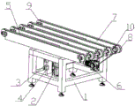
Fig. 1 is the utility model structural representation.
Fig. 2 is the forward sight structural representation of Fig. 1.
The specific embodiment
As Fig. 1, shown in 2, the utility model is made up of jacking system and transmitting device, jacking system is by frame 1, cylinder 2, one group of guide rod 3, one group chamber type linear bearing 4 and crane 5 are formed, cylinder 2 is installed on the frame 1, one group chamber type linear bearing 4 is installed on the frame 1, one group of guide rod 3 is slidingly mounted on respectively on the group chamber type linear bearing 4, crane 5 is installed in the piston rod part of one group of guide rod 3 and cylinder 2, transmitting device is by motor 6, one group of base 7, one group of A synchronous pulley 8 and one group of B synchronous pulley 9 are formed, motor 6 is installed on the frame 1, one group of base 7 is installed in respectively on the frame 1, one group of A synchronous pulley 8 and one group of B synchronous pulley 9 are installed in the two ends of one group of base 7 respectively by bearing seat, one group of A synchronous pulley 8 links to each other by 10 transmissions of A movable axis, one group of B synchronous pulley 9 links to each other by the transmission of B movable axis, the power take-off shaft of motor 6 links to each other with 10 transmissions of A movable axis by being with synchronously, and one group of A synchronous pulley 8 links to each other with one group of B synchronous pulley 9 transmission by synchronous band respectively.
Using method: during transporting glass, cylinder 2 rises, driving crane 5 moves up, meanwhile, one group of guide rod 3 is also driven thereupon, thereby guarantee the rigidity of jacking system, epimere equipment be sucker grasp glass can only parallel motion mechanism, it is highly located by the 5mm that sucker extracting glass is moved horizontally to crane 5, vacuum breaker is decontroled glass to crane, cylinder 2 returns descend then, be positioned over one group until the glass on the crane 5 and be with synchronously, starter motor 6 drives A movable axis 10, one group of A synchronous pulley 8, one group of band and one group of B synchronous pulley 9 rotation synchronously, at last glass is transported on next manufacturing line, thereby the line of finishing different operating height equipment transmits.
Claims (1)
1. lifting transmitting device that is used for the vehicle glass manufacturing line, it is characterized in that it is made up of jacking system and transmitting device, jacking system is by frame (1), cylinder (2), one group of guide rod (3), one group chamber type linear bearing (4) and crane (5) are formed, cylinder (2) is installed on the frame (1), one group chamber type linear bearing (4) is installed on the frame (1), one group of guide rod (3) is slidingly mounted on respectively on the group chamber type linear bearing (4), crane (5) is installed in the piston rod part of one group of guide rod (3) and cylinder (2), transmitting device is by motor (6), one group of base (7), one group of A synchronous pulley (8) and one group of B synchronous pulley (9) are formed, motor (6) is installed on the frame (1), one group of base (7) is installed in respectively on the frame (1), one group of A synchronous pulley (8) and one group of B synchronous pulley (9) are installed in the two ends of one group of base (7) respectively by bearing seat, one group of A synchronous pulley (8) links to each other by A movable axis (10) transmission, one group of B synchronous pulley (9) links to each other by the transmission of B movable axis, the power take-off shaft of motor (6) links to each other with A movable axis (10) transmission by being with synchronously, and one group of A synchronous pulley (8) links to each other with one group of B synchronous pulley (9) transmission by synchronous band respectively.
Priority Applications (1)
| Application Number | Priority Date | Filing Date | Title |
|---|---|---|---|
| CN 201320030130 CN203173456U (en) | 2013-01-21 | 2013-01-21 | Lifting transportation device for automobile glass production line |
Applications Claiming Priority (1)
| Application Number | Priority Date | Filing Date | Title |
|---|---|---|---|
| CN 201320030130 CN203173456U (en) | 2013-01-21 | 2013-01-21 | Lifting transportation device for automobile glass production line |
Publications (1)
| Publication Number | Publication Date |
|---|---|
| CN203173456U true CN203173456U (en) | 2013-09-04 |
Family
ID=49070193
Family Applications (1)
| Application Number | Title | Priority Date | Filing Date |
|---|---|---|---|
| CN 201320030130 Expired - Fee Related CN203173456U (en) | 2013-01-21 | 2013-01-21 | Lifting transportation device for automobile glass production line |
Country Status (1)
| Country | Link |
|---|---|
| CN (1) | CN203173456U (en) |
Cited By (3)
| Publication number | Priority date | Publication date | Assignee | Title |
|---|---|---|---|---|
| CN103264891A (en) * | 2013-01-21 | 2013-08-28 | 福耀玻璃(湖北)有限公司 | Lifting and transmitting device for automotive glass production line |
| CN104003169A (en) * | 2014-05-30 | 2014-08-27 | 安徽鲲鹏装备模具制造有限公司 | Refrigerator model division pre-installation box buffer warehouse and control |
| CN104129607A (en) * | 2013-12-21 | 2014-11-05 | 中国重汽集团柳州运力专用汽车有限公司 | Lifting device for transferring floor on production lines |
-
2013
- 2013-01-21 CN CN 201320030130 patent/CN203173456U/en not_active Expired - Fee Related
Cited By (3)
| Publication number | Priority date | Publication date | Assignee | Title |
|---|---|---|---|---|
| CN103264891A (en) * | 2013-01-21 | 2013-08-28 | 福耀玻璃(湖北)有限公司 | Lifting and transmitting device for automotive glass production line |
| CN104129607A (en) * | 2013-12-21 | 2014-11-05 | 中国重汽集团柳州运力专用汽车有限公司 | Lifting device for transferring floor on production lines |
| CN104003169A (en) * | 2014-05-30 | 2014-08-27 | 安徽鲲鹏装备模具制造有限公司 | Refrigerator model division pre-installation box buffer warehouse and control |
Similar Documents
| Publication | Publication Date | Title |
|---|---|---|
| CN101428660B (en) | Ski reciprocation conveying system branch station lifting mechanism for white car body assembly production line | |
| CN103264891A (en) | Lifting and transmitting device for automotive glass production line | |
| CN203527964U (en) | Full-automatic box pasting machine | |
| CN203173456U (en) | Lifting transportation device for automobile glass production line | |
| CN204607220U (en) | X-axis horizontal shifting two lifting adsorption system | |
| CN202684499U (en) | Disposable assembly device of oil cylinder | |
| CN105479788A (en) | Small-tabletop link punch | |
| CN204110415U (en) | One gets carton combination | |
| CN202924415U (en) | Workpiece automatic delivery device | |
| CN204014891U (en) | Absorption type stripper apparatus | |
| CN201592888U (en) | Stepped type stepping device | |
| CN203094952U (en) | Soft-landing conveying mechanism | |
| CN204751521U (en) | Pile up neatly forming device of material in hacking machine | |
| CN204872923U (en) | Hacking machine | |
| CN203844083U (en) | Refrigerator foaming clamp driven to lift up and down by novel air cylinders | |
| CN205046903U (en) | Stereo garage gear formula translation power transmission mechanism | |
| CN204262230U (en) | A kind of automatic charging device of stamping machine | |
| CN203048043U (en) | Transverse movement mechanism of greenhouse potted flowers transport device | |
| CN203269088U (en) | Novel brick stacking machine | |
| CN203187223U (en) | Bobbin-pressing device | |
| CN204196438U (en) | The defeated paper platform of offset press rises control device automatically | |
| CN204953788U (en) | Adopt transmission system of servo press of many motor drive of different belts | |
| CN103480763A (en) | Rotation linear composite electromagnetic servo direct drive feed device for covering part stamping production line | |
| CN203318713U (en) | Automatic sub-packaging equipment for magnetic cores | |
| CN103112757B (en) | Bobbin pressing device |
Legal Events
| Date | Code | Title | Description |
|---|---|---|---|
| C14 | Grant of patent or utility model | ||
| GR01 | Patent grant | ||
| EE01 | Entry into force of recordation of patent licensing contract |
Assignee: ZHENGZHOU FUYAO GLASS CO., LTD. Assignor: Fuyao Glass (Hubei) Co., Ltd. Contract record no.: 2015420000028 Denomination of utility model: Lifting and transmitting device for automotive glass production line Granted publication date: 20130904 License type: Exclusive License Record date: 20150318 |
|
| LICC | Enforcement, change and cancellation of record of contracts on the licence for exploitation of a patent or utility model | ||
| CF01 | Termination of patent right due to non-payment of annual fee | ||
| CF01 | Termination of patent right due to non-payment of annual fee |
Granted publication date: 20130904 Termination date: 20200121 |