CN203151433U - Double-frequency synchronous power amplifier based on T-type network and coupling line - Google Patents
Double-frequency synchronous power amplifier based on T-type network and coupling line Download PDFInfo
- Publication number
- CN203151433U CN203151433U CN201220472136.9U CN201220472136U CN203151433U CN 203151433 U CN203151433 U CN 203151433U CN 201220472136 U CN201220472136 U CN 201220472136U CN 203151433 U CN203151433 U CN 203151433U
- Authority
- CN
- China
- Prior art keywords
- frequency
- double frequency
- power amplifier
- double
- line
- Prior art date
- Legal status (The legal status is an assumption and is not a legal conclusion. Google has not performed a legal analysis and makes no representation as to the accuracy of the status listed.)
- Expired - Lifetime
Links
- 230000008878 coupling Effects 0.000 title claims abstract description 29
- 238000010168 coupling process Methods 0.000 title claims abstract description 29
- 238000005859 coupling reaction Methods 0.000 title claims abstract description 29
- 230000001360 synchronised effect Effects 0.000 title claims abstract description 20
- 230000005540 biological transmission Effects 0.000 claims description 87
- 230000008054 signal transmission Effects 0.000 claims description 2
- 230000009466 transformation Effects 0.000 claims description 2
- 238000005516 engineering process Methods 0.000 abstract description 5
- 238000004891 communication Methods 0.000 abstract description 4
- 239000000843 powder Substances 0.000 abstract 1
- 238000000034 method Methods 0.000 description 9
- 230000008569 process Effects 0.000 description 5
- 238000010295 mobile communication Methods 0.000 description 2
- 239000010754 BS 2869 Class F Substances 0.000 description 1
- 230000003321 amplification Effects 0.000 description 1
- 230000009286 beneficial effect Effects 0.000 description 1
- 230000008901 benefit Effects 0.000 description 1
- 230000008859 change Effects 0.000 description 1
- 230000007812 deficiency Effects 0.000 description 1
- 238000003199 nucleic acid amplification method Methods 0.000 description 1
- 238000005457 optimization Methods 0.000 description 1
- 238000004088 simulation Methods 0.000 description 1
Images


Landscapes
- Amplifiers (AREA)
- Microwave Amplifiers (AREA)
Abstract
Description
技术领域 technical field
本实用新型属于无线通信技术的功率放大器设计领域。特别涉及一种基于T型网络和耦合线的双频同步式功率放大器。尤其是用于多频段、高效的移动通信基站末级射频输出中的一种支持双频段的同步式功率放大器。 The utility model belongs to the field of power amplifier design of wireless communication technology. In particular, it relates to a dual-frequency synchronous power amplifier based on a T-shaped network and a coupling line. In particular, it is a dual-band synchronous power amplifier used in the final radio frequency output of a multi-band, high-efficiency mobile communication base station. the
背景技术 Background technique
为了实现“绿色”通信的新理念,高效功率放大器正受到越来越多的关注和重视。目前有几种技术能够达到高效率的目的。一些工作模式如E类、F类功放能够达到很高的漏极效率,理想状态下达到100%的漏极效率,但是这类功放的缺点是线性度比较差。Doherty(多尔蒂)结构的功放兼有较高的效率(相对于AB类放大器)和较好线性度(相对于C类放大器),目前已广泛地应用于无线通信基站当中。但是由于其结构特点,带宽受到限制,无法满足宽带系统的要求。Doherty电路的基本原理是将输入信号的平均部分和峰值部分分开放大,然后合成,从而获得高效率。由于Doherty结构的有源负载牵引特性,使得功放能在一定功率回退的范围内保证较高效率,满足不同峰均比调制信号的放大需求。数字预失真技术与Doherty功放相结合,可以实现高效率、高线性功放。 In order to realize the new concept of "green" communication, high-efficiency power amplifiers are receiving more and more attention and attention. Several techniques are currently available to achieve high efficiency. Some working modes such as Class E and Class F power amplifiers can achieve very high drain efficiency, and ideally reach 100% drain efficiency, but the disadvantage of this type of power amplifier is that its linearity is relatively poor. The Doherty (Doherty) structure power amplifier has both higher efficiency (compared to class AB amplifier) and better linearity (compared to class C amplifier), and has been widely used in wireless communication base stations. However, due to its structural characteristics, the bandwidth is limited and cannot meet the requirements of broadband systems. The basic principle of the Doherty circuit is to separately amplify the average part and the peak part of the input signal, and then synthesize them to obtain high efficiency. Due to the active load-pulling characteristics of the Doherty structure, the power amplifier can guarantee higher efficiency within a certain power back-off range, and meet the amplification requirements of modulation signals with different peak-to-average ratios. The combination of digital pre-distortion technology and Doherty power amplifier can realize high efficiency and high linearity power amplifier. the
随着技术发展,未来移动通信系统需要同时支持不同的标准,这就要求基站发射机终端能够同时处理不同频率的信号,因此多频段工作的功率放大器将得到很大应用。为了实现多频段工作,一些设计功放的方法被提出来。其中有一类功放用并联功放实现多频工作,每个功放调节到单频最佳工作状态,需要时使用开关选择适合的功放处理不同频率的信号。这类功放的设计方法简单,但是成本很高,而且不能同时处理多频信号。另外一类功放使用可重构的负载网络实现多频 工作,这类功放的负载网络中包含一些可调节的元件,如微机电系统,可变电容二极管等,通过电压控制这些元件改变负载网络参数,使其在某一频率实现最佳工作状态。这类功放的电压控制比较难,而且不能同时处理多频信号。第三类功放使用多频带通网络实现多频工作,这类功放的设计比较复杂,优点是它能同时处理多频信号。 With the development of technology, the future mobile communication system needs to support different standards at the same time, which requires the base station transmitter terminal to be able to process signals of different frequencies at the same time, so power amplifiers working in multiple frequency bands will be widely used. In order to realize multi-band work, some methods of designing power amplifiers have been proposed. Among them, there is a type of power amplifier that uses parallel power amplifiers to achieve multi-frequency work. Each power amplifier is adjusted to the best working state of a single frequency. When necessary, use a switch to select a suitable power amplifier to process signals of different frequencies. The design method of this type of power amplifier is simple, but the cost is very high, and it cannot process multi-frequency signals at the same time. Another type of power amplifier uses a reconfigurable load network to achieve multi-frequency operation. The load network of this type of power amplifier contains some adjustable components, such as micro-electromechanical systems, variable capacitance diodes, etc., and these components are controlled by voltage to change the parameters of the load network. , so that it can achieve the best working condition at a certain frequency. The voltage control of this type of power amplifier is more difficult, and it cannot handle multi-frequency signals at the same time. The third type of power amplifier uses a multi-frequency band-pass network to achieve multi-frequency work. The design of this type of power amplifier is relatively complicated, and the advantage is that it can process multi-frequency signals at the same time. the
传统的Doherty功放由一个功分器加一段四分之一波长传输线、一个主功放、一个辅功放、两段延迟线、一段四分之一波长传输线组成,因为这些组成元件只能工作在一个频率下,所以传统Doherty功放只能工作在单一频段上。 The traditional Doherty power amplifier consists of a power divider plus a quarter-wavelength transmission line, a main power amplifier, an auxiliary power amplifier, two delay lines, and a quarter-wavelength transmission line, because these components can only work at one frequency Therefore, the traditional Doherty power amplifier can only work in a single frequency band. the
目前,基于一些双频结构,一些无源器件能够实现双频同步工作。在一些文章中,一种T型网络被用来实现双频的定向耦合器,这种定向耦合器与传统的定向耦合器结构相同,不同点在于其中的每段四分之一波长的传输线被T型网络代替。这种T型网络包含两段串联传输线和一段置于中间的分支线,分支线可以是短路到地的,也可以是开路的。这种定向耦合器能够实现在任意两个不同频率下,将输入功率等分到两个输出端口并附加90°的相位差。在一些文章中,耦合线被用来实现双频工作的Wilkinson(威尔金森)功分器,耦合线可以是单节的也可以是双节的。耦合线的功能是代替了传统Wilkinson功分器中的四分之一波长的传输线,在两个不同频率下都显示出四分之一波长的相位延迟特性。使用T型网络的特点是其频率比能做很大,缺点是其尺寸比较大,频率比比较大时,其中分支线可能很细(末端开路)或者很粗(末端短路)。耦合线的特点是尺寸比较小,缺点是其频率比范围较小,当参数设定正确后,T型网络或者耦合线都能等效为一段双频的传输线 At present, based on some dual-frequency structures, some passive devices can realize dual-frequency synchronous operation. In some articles, a T-type network is used to implement a dual-band directional coupler. This directional coupler has the same structure as a traditional directional coupler. The difference is that each quarter-wavelength transmission line is T-network instead. This T-network consists of two series transmission lines and a branch line placed in the middle. The branch line can be shorted to ground or open. This directional coupler can divide the input power equally to two output ports and add a 90° phase difference at any two different frequencies. In some articles, coupled lines are used to realize dual-frequency Wilkinson (Wilkinson) power dividers, and the coupled lines can be single-section or double-section. The function of the coupled line is to replace the quarter-wavelength transmission line in the traditional Wilkinson power splitter, and it shows a quarter-wavelength phase delay characteristic at two different frequencies. The characteristic of using a T-shaped network is that its frequency ratio can be made very large. The disadvantage is that its size is relatively large. When the frequency ratio is relatively large, the branch line may be very thin (open end) or thick (short circuit at the end). The characteristic of the coupled line is that the size is relatively small, and the disadvantage is that its frequency ratio range is small. When the parameters are set correctly, the T-type network or the coupled line can be equivalent to a dual-frequency transmission line.
实用新型内容 Utility model content
本实用新型的目的是针对现有技术的不足提供一种基于T型网络和耦合线的 双频同步式功率放大器,其特征在于,所述基于T型网络和耦合线的双频同步式功放具有双路或者多路双频Doherty功放,包括两种结构:一种是一个双频主功放和一个双频辅助功放分别连接至双频双路功分器加90°相位差输出的功分器模块;双频定向耦合器或双频双路功分器加90°相位差输出的功分器模块与输入端连接,双频主功放和双频辅助功放分别与主双频延迟线和辅双频延迟线连接,主双频延迟线与第一段双频四分之一波长传输线连接,第一段双频四分之一波长传输线与辅双频延迟线和第二双频四分之一波长传输线连接在一起,第二段双频四分之一波长传输线连接输出端;另一种是一个双频主功放和第一双频辅助功放至第N双频辅助功放分别与双频双路功分器加90°相位差输出的功分器模块连接;双频主功放与主双频延迟线连接,主双频延迟线与第一段双频四分之一波长传输线连接,第一双频辅助功放至第N双频辅助功放对应地与第一双频延迟线至第N双频延迟线连接,第一双频延迟线至第N双频延迟线公共节点再与第一段双频四分之一波长传输线和第二段双频四分之一波长传输线的公共节点连接,第二段双频四分之一波长传输线连接输出端。 The purpose of this utility model is to provide a kind of dual-frequency synchronous power amplifier based on T-type network and coupling line for the deficiencies in the prior art, it is characterized in that, the dual-frequency synchronous power amplifier based on T-type network and coupling line has Dual-channel or multi-channel dual-frequency Doherty power amplifier, including two structures: one is a dual-frequency main power amplifier and a dual-frequency auxiliary power amplifier connected to the dual-frequency dual-channel power splitter plus 90° phase difference output power splitter module ;Dual-frequency directional coupler or dual-frequency dual-channel power divider plus 90° phase difference output power divider module is connected to the input terminal, and the dual-frequency main power amplifier and dual-frequency auxiliary power amplifier are respectively connected to the main dual-frequency delay line and auxiliary dual-frequency Delay line connection, the main dual-frequency delay line is connected to the first dual-frequency quarter-wavelength transmission line, and the first dual-frequency quarter-wavelength transmission line is connected to the auxiliary dual-frequency delay line and the second dual-frequency quarter-wavelength transmission line The transmission lines are connected together, and the second section of the dual-frequency quarter-wavelength transmission line is connected to the output end; the other is a dual-frequency main power amplifier and the first dual-frequency auxiliary power amplifier to the Nth dual-frequency auxiliary power amplifier. The splitter plus 90° phase difference output power splitter module is connected; the dual-frequency main power amplifier is connected to the main dual-frequency delay line, the main dual-frequency delay line is connected to the first dual-frequency quarter-wavelength transmission line, and the first dual-frequency The auxiliary power amplifier to the Nth dual-frequency auxiliary power amplifier are correspondingly connected to the first dual-frequency delay line to the Nth dual-frequency delay line, and the common node of the first dual-frequency delay line to the Nth dual-frequency delay line is connected to the first dual-frequency four The quarter-wavelength transmission line is connected to the common node of the second section of the dual-frequency quarter-wavelength transmission line, and the second section of the dual-frequency quarter-wavelength transmission line is connected to the output end. the
所述N为1-20个。 The N is 1-20. the
所述第一段双频四分之一波长传输线特性阻抗为50Ω,第二段双频四分之一波长传输线特性阻抗为35Ω。 The characteristic impedance of the first dual-frequency quarter-wavelength transmission line is 50Ω, and the characteristic impedance of the second dual-frequency quarter-wavelength transmission line is 35Ω. the
所述基于T型网络和耦合线包括双频工作的四分之一波长传输线和双频工作的延迟线;T型网络由双频四分之一波长传输线组成,并串联在信号传输路上;其中,双频定向耦合器由四段双频四分之一波长传输线组成,其中上下两段双频四分之一波长传输线具有
所述耦合线为单节耦合线或两节耦合线。 The coupled line is a single-section coupled line or a two-section coupled line. the
所述双频Doherty功放含有一段双频定向耦合器或双频定向耦合器或双频双路功分器加90°相位差输出的功分器模块、一个双频主功放、一个双频辅助功放、两段双频延迟线,两段特性阻抗分别为50Ω和35Ω的双频四分之一波长阻抗变换线;其中,双频定向耦合器由4个T型网络组成,其中上下两个T型网络具有等效
所述双频四分之一波长传输线或者双频延迟线为单节耦合线、双节耦合线、带短路分支线的T型网络或者带开路分支线的T型网络。 The dual-frequency quarter-wavelength transmission line or the dual-frequency delay line is a single-section coupled line, a double-section coupled line, a T-type network with a short-circuit branch line, or a T-type network with an open-circuit branch line. the
所述双频功分器加90°相位差输出模块由双频定向耦合器,或者双频威尔金森功分器加双频四分之一波长传输线实现;双频定向耦合器和双频威尔金森功分器是由双频四分之一波长传输线构成。 The dual-frequency power divider plus a 90° phase difference output module is realized by a dual-frequency directional coupler, or a dual-frequency Wilkinson power divider plus a dual-frequency quarter-wavelength transmission line; the dual-frequency directional coupler and the dual-frequency Wei The Wilkinson power divider is composed of a dual-frequency quarter-wavelength transmission line. the
本实用新型的有益效果是该功放能够同时工作在任意两种频段上,本发明的 双频Doherty功放能够同时处理两种不同频率的信号,在不同频带上均能实现效率的提高。双频Doherty在单个频带上的表现与传统Doherty功放相同,能提高小功率区的效率,在大功率区保持高效率,当放大峰均比较大的信号时,功放的效率比普通功放要高很多。双频Doherty功放在两个频段同时工作时,由于交调的影响会使功放的线性度有所下降,通过预失真技术可以提高该功放的线性度。 The beneficial effect of the utility model is that the power amplifier can work on any two frequency bands at the same time, and the dual-frequency Doherty power amplifier of the present invention can process signals of two different frequencies at the same time, and the efficiency can be improved in different frequency bands. The performance of dual-band Doherty in a single frequency band is the same as that of traditional Doherty power amplifiers. It can improve the efficiency in low-power areas and maintain high efficiency in high-power areas. When amplifying signals with a relatively large peak-to-average ratio, the efficiency of the power amplifier is much higher than that of ordinary power amplifiers. . When the dual-band Doherty power amplifier works in two frequency bands at the same time, the linearity of the power amplifier will decrease due to the influence of intermodulation, and the linearity of the power amplifier can be improved by pre-distortion technology. the
附图说明 Description of drawings
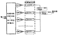
图1为双频双路Doherty功放的设计模型。 Figure 1 is the design model of the dual-frequency dual-channel Doherty power amplifier. the
图2为双频多路Doherty功放的设计模型。 Figure 2 is the design model of the dual-frequency multi-channel Doherty power amplifier. the
图3(a)为双频传输线的等效模型,图3(b)为单节耦合线,图3(c)为双节耦合线,图3(d)为带短路分支线的T型网络,图3(e)为带开路分支线的T型网络。 Figure 3(a) is the equivalent model of a dual-frequency transmission line, Figure 3(b) is a single-section coupled line, Figure 3(c) is a double-section coupled line, and Figure 3(d) is a T-shaped network with a short-circuit branch line , Figure 3(e) is a T-shaped network with an open branch line. the
图4(a)为双频定向耦合器,图4(b)为双频Wilkinson功分器加四分之一波长延迟线模块。 Figure 4(a) is a dual-frequency directional coupler, and Figure 4(b) is a dual-frequency Wilkinson power divider plus a quarter-wavelength delay line module. the
图5为双频单路功率放大器 Figure 5 is a dual-frequency single-channel power amplifier
具体实施方式 Detailed ways
一种基于T型网络和耦合线的双频同步式功率放大器首先需要确定双频Doherty功放的结构模型,传统的Doherty功放为双路模型,后来发展出多路模型,本发明提出的双频Doherty功放模型也分为双路和多路模型。如图1所示为一个双频双路Doherty功放模型,其结构与传统单频双路Doherty功放一样,具体结构是一个双频主功放和一个双频辅助功放分别连接至双频双路功分器加90°相位差输出的功分器模块;双频定向耦合器或双频双路功分器加90°相位差输出的功分器模块与输入端连接,双频主功放和双频辅助功放分别与主双频延迟线和辅双频延迟线连接,主双频延迟线与第一段双频四分之一波长传输线连接,第一段双频四分之一波长传输线与辅双频延迟线和第二双频四分之一波长传输 线连接在一起,第二段双频四分之一波长传输线连接输出端;其中的各个元件均为双频模型,双频传输线(延迟线及四分之一波长传输线)。双频双路功率分配及90°相位差输出模块可以用定向耦合器,也可用Wilkinson功分加90°延迟线实现。图2为一个多路双频Doherty功放模型,与双路模型不同的是,它含有多个辅助功放,因此其前级需要一个多路功分器将功率分配到各个功放。三路功分器可独立实现,三路以上的功分器可以用多个功分级联实现。具体结构是一个双频主功放和第一双频辅助功放至第N双频辅助功放分别与双频双路功分器加90°相位差输出的功分器模块连接;双频主功放与主双频延迟线连接,主双频延迟线与第一段双频四分之一波长传输线连接,第一双频辅助功放至第N双频辅助功放对应地与第一双频延迟线至第N双频延迟线连接,第一双频延迟线至第N双频延迟线公共节点再与第一段双频四分之一波长传输线和第二段双频四分之一波长传输线的公共节点连接,第二段双频四分之一波长传输线连接输出端。 A kind of dual-frequency synchronous type power amplifier based on T-type network and coupling line first needs to determine the structural model of dual-frequency Doherty power amplifier, traditional Doherty power amplifier is a dual-channel model, develops a multi-channel model later, the dual-frequency Doherty power amplifier proposed by the present invention The power amplifier model is also divided into two-way and multi-way models. Figure 1 shows a dual-frequency dual-channel Doherty power amplifier model. Its structure is the same as that of the traditional single-frequency dual-channel Doherty power amplifier. The specific structure is that a dual-frequency main power amplifier and a dual-frequency auxiliary power amplifier are respectively connected to the dual-frequency dual-channel power distribution Power splitter module with 90° phase difference output; dual-frequency directional coupler or dual-frequency dual-way power splitter plus 90° phase difference output power splitter module is connected to the input terminal, dual-frequency main power amplifier and dual-frequency auxiliary The power amplifier is connected to the main dual-frequency delay line and the auxiliary dual-frequency delay line respectively, the main dual-frequency delay line is connected to the first dual-frequency quarter-wavelength transmission line, and the first dual-frequency quarter-wavelength transmission line is connected to the auxiliary dual-frequency The delay line and the second dual-frequency quarter-wavelength transmission line are connected together, and the second dual-frequency quarter-wavelength transmission line is connected to the output end; each component in it is a dual-frequency model, and the dual-frequency transmission line (delay line and quarter wavelength transmission line). The dual-frequency dual-channel power distribution and 90° phase difference output module can be implemented with a directional coupler, or with a Wilkinson power divider plus a 90° delay line. Figure 2 shows a multi-channel dual-frequency Doherty power amplifier model, which is different from the dual-channel model in that it contains multiple auxiliary power amplifiers, so a multi-channel power divider is required to distribute power to each power amplifier in its front stage. Three-way power splitters can be realized independently, and more than three-way power splitters can be realized by multiple power stages. The specific structure is that a dual-frequency main power amplifier and the first dual-frequency auxiliary power amplifier to the Nth dual-frequency auxiliary power amplifier are respectively connected to the power splitter module of the dual-frequency dual-way power divider plus 90° phase difference output; the dual-frequency main power amplifier is connected to the main Dual-frequency delay line connection, the main dual-frequency delay line is connected to the first dual-frequency quarter-wavelength transmission line, and the first dual-frequency auxiliary power amplifier to the Nth dual-frequency auxiliary power amplifier are correspondingly connected to the first dual-frequency delay line to the Nth Dual-frequency delay line connection, the common node of the first dual-frequency delay line to the Nth dual-frequency delay line is connected to the common node of the first dual-frequency quarter-wavelength transmission line and the second dual-frequency quarter-wavelength transmission line , the second section of the dual-frequency quarter-wavelength transmission line is connected to the output end. the
设计双频Doherty功放中的双频传输线如图3(a)所示的双频传输线的等效模型,设计要求该传输线实现同步工作在频率f1和f2的条件为:这种传输线可以等效为一段普通传输线,在第一个频率具有Zc1的等效特性阻抗和θ1的等效电长度,在第二个频率具有Zc2的等效特性阻抗和θ2的等效电长度。耦合线和T型网络都具有这种特性。图3(b)为单节耦合线结构,图3(c)为双节耦合线结构,图3(d)为带短路分支线的T型网络,图3(e)为带开路分支线的T型网络。 Designing the equivalent model of the dual-frequency transmission line in the dual-frequency Doherty power amplifier shown in Figure 3(a), the design requires the transmission line to achieve synchronous operation at frequencies f 1 and f 2. The conditions are: this transmission line can wait It is effectively a section of ordinary transmission line, which has an equivalent characteristic impedance of Z c1 and an equivalent electrical length of θ 1 at the first frequency, and an equivalent characteristic impedance of Z c2 and an equivalent electrical length of θ 2 at the second frequency. Both coupled lines and T-networks have this property. Figure 3(b) is a single-section coupled line structure, Figure 3(c) is a double-section coupled line structure, Figure 3(d) is a T-shaped network with a short-circuit branch line, and Figure 3(e) is a T-shaped network with an open-circuit branch line T-network.
在双频Doherty功放模型中,前级需要一个双频功分器及90°相位差输出模块。这个模块可以用双频定向耦合器实现,如图4(a)所示;也可以用双频Wilkinson功分器加双频四分之一波长传输线实现,如图4(b)所示。双频定向耦合器由四段双频四分之一波长传输线组成,其中上下两段(分别为第三段双频四分之一波长传输线和第五段双频四分之一波长传输线)传输线具有

在双频Doherty功放中,主功放和辅功放均为单路双频功放。本发明使用一种单路双频功放如图5所示,输入匹配网络为п型结构,通过优化可得到两个频率处的共轭匹配;负载网络包含一段并联开路传输线,一个带短路分支线的T型网络,在两个频率点该网络可以将标准负载变换到需要的最佳阻抗。直流偏置电压将该功放设置为AB类工作模式(主功放)或者C类工作模式(辅助功放),直流供电电压直接通过短路分支线连接到晶体管漏极。 In a dual-band Doherty power amplifier, both the main power amplifier and the auxiliary power amplifier are single-channel dual-band power amplifiers. The present invention uses a single-channel dual-frequency power amplifier as shown in Figure 5. The input matching network is a п-type structure, and the conjugate matching at two frequencies can be obtained through optimization; the load network includes a section of parallel open-circuit transmission line, a short-circuit branch line T-shaped network, which can transform the standard load to the best impedance required at two frequency points. The DC bias voltage sets the power amplifier to a Class AB working mode (main power amplifier) or a Class C working mode (auxiliary power amplifier), and the DC supply voltage is directly connected to the drain of the transistor through a short-circuited branch line. the
有了双频传输线,双频功分器和双频单路功放,一个如图1所示双频双路Doherty功放或者图2所示的双频多路Doherty功放就能够实现。在仿真中,通过调节双频延迟线的等效电长度,可以优化得到Doherty功放的最佳工作性能。 With the dual-frequency transmission line, dual-frequency power splitter and dual-frequency single-channel power amplifier, a dual-frequency dual-channel Doherty power amplifier as shown in Figure 1 or a dual-frequency multi-channel Doherty power amplifier as shown in Figure 2 can be realized. In the simulation, by adjusting the equivalent electrical length of the dual-frequency delay line, the best working performance of the Doherty power amplifier can be optimized. the
验证双频Doherty功放的可行性,使用SiC MESFET24010器件设计的双频900MHz和2GHz的基于T型网络双路Doherty功放,在高频段测量的漏极效率对比结果显示,在最大输出功率回退9dB处,双频三路Doherty功放的漏极效率比平衡式放大器的漏极效率提高了20%。 To verify the feasibility of the dual-band Doherty power amplifier, the dual-frequency 900MHz and 2GHz dual-frequency Doherty power amplifier based on the T-shaped network designed with the SiC MESFET24010 device, the drain efficiency comparison results measured in the high frequency band show that the maximum output power retreats 9dB , The drain efficiency of the dual-frequency three-way Doherty power amplifier is 20% higher than that of the balanced amplifier. the
Claims (7)


Priority Applications (1)
| Application Number | Priority Date | Filing Date | Title |
|---|---|---|---|
| CN201220472136.9U CN203151433U (en) | 2012-09-14 | 2012-09-14 | Double-frequency synchronous power amplifier based on T-type network and coupling line |
Applications Claiming Priority (1)
| Application Number | Priority Date | Filing Date | Title |
|---|---|---|---|
| CN201220472136.9U CN203151433U (en) | 2012-09-14 | 2012-09-14 | Double-frequency synchronous power amplifier based on T-type network and coupling line |
Publications (1)
| Publication Number | Publication Date |
|---|---|
| CN203151433U true CN203151433U (en) | 2013-08-21 |
Family
ID=48978924
Family Applications (1)
| Application Number | Title | Priority Date | Filing Date |
|---|---|---|---|
| CN201220472136.9U Expired - Lifetime CN203151433U (en) | 2012-09-14 | 2012-09-14 | Double-frequency synchronous power amplifier based on T-type network and coupling line |
Country Status (1)
| Country | Link |
|---|---|
| CN (1) | CN203151433U (en) |
Cited By (5)
| Publication number | Priority date | Publication date | Assignee | Title |
|---|---|---|---|---|
| WO2015117506A1 (en) * | 2014-08-21 | 2015-08-13 | 中兴通讯股份有限公司 | Signal amplification device and method, base station and system |
| CN107493075A (en) * | 2016-06-09 | 2017-12-19 | 恩智浦美国有限公司 | Doherty amplifier with minimum phase output network |
| CN110932743A (en) * | 2018-09-17 | 2020-03-27 | 天津大学青岛海洋技术研究院 | Vital sign Doppler radar circuit structure with double-frequency isolation effect |
| CN111641390A (en) * | 2020-06-15 | 2020-09-08 | 重庆邮电大学 | High-efficiency Doherty power amplifier based on T-PI type combiner network and design method |
| CN117674747A (en) * | 2024-01-31 | 2024-03-08 | 苏州悉芯射频微电子有限公司 | High-linearity high-efficiency non-pair Doherty power amplifier |
-
2012
- 2012-09-14 CN CN201220472136.9U patent/CN203151433U/en not_active Expired - Lifetime
Cited By (9)
| Publication number | Priority date | Publication date | Assignee | Title |
|---|---|---|---|---|
| WO2015117506A1 (en) * | 2014-08-21 | 2015-08-13 | 中兴通讯股份有限公司 | Signal amplification device and method, base station and system |
| CN105375891A (en) * | 2014-08-21 | 2016-03-02 | 中兴通讯股份有限公司 | Signal amplification device and method, base station and system |
| CN107493075A (en) * | 2016-06-09 | 2017-12-19 | 恩智浦美国有限公司 | Doherty amplifier with minimum phase output network |
| CN107493075B (en) * | 2016-06-09 | 2023-01-31 | 恩智浦美国有限公司 | Doherty amplifier with minimum phase output network |
| CN110932743A (en) * | 2018-09-17 | 2020-03-27 | 天津大学青岛海洋技术研究院 | Vital sign Doppler radar circuit structure with double-frequency isolation effect |
| CN111641390A (en) * | 2020-06-15 | 2020-09-08 | 重庆邮电大学 | High-efficiency Doherty power amplifier based on T-PI type combiner network and design method |
| CN111641390B (en) * | 2020-06-15 | 2023-06-02 | 重庆邮电大学 | High Efficiency Doherty Power Amplifier Based on T-PI Combining Network and Its Design Method |
| CN117674747A (en) * | 2024-01-31 | 2024-03-08 | 苏州悉芯射频微电子有限公司 | High-linearity high-efficiency non-pair Doherty power amplifier |
| CN117674747B (en) * | 2024-01-31 | 2024-04-12 | 苏州悉芯射频微电子有限公司 | High-linearity high-efficiency non-pair Doherty power amplifier |
Similar Documents
| Publication | Publication Date | Title |
|---|---|---|
| CN102868368A (en) | Double-frequency synchronous power amplifier based on T-type network and coupling line and design method thereof | |
| CN112543002B (en) | Broadband differential Doherty power amplifier and its design method and application | |
| WO2012079542A1 (en) | Doherty power amplifier | |
| CN103457541A (en) | Method for widening bandwidth of Doherty power amplifier and Doherty power amplifier improved with method | |
| WO2017008512A1 (en) | Doherty power amplifier circuit | |
| CN103986422B (en) | A kind of dual band radio frequency power amplifier impedance match circuit | |
| CN203151433U (en) | Double-frequency synchronous power amplifier based on T-type network and coupling line | |
| Nguyen et al. | A coupler-based differential Doherty power amplifier with built-in baluns for high mm-wave linear-yet-efficient Gbit/s amplifications | |
| CN102801387A (en) | Dual-mode dual-band high-efficiency Doherty power amplifier | |
| CN111030620A (en) | Novel combined broadband Doherty power amplifier and design method thereof | |
| CN106411265B (en) | A kind of asymmetric Doherty power amplifier with extended bandwidth and its realization method | |
| CN104917472A (en) | Power amplifier circuit, power amplification device and broadband matching method of power amplification device | |
| CN107332519A (en) | A kind of broadband Doherty power amplifier and its implementation that combiner is exported based on modified | |
| CN103281040A (en) | On-chip power amplifier synthesized based on power of eight branches of fully symmetrical transformers | |
| CN107508560B (en) | Doherty power amplifier for enhancing bandwidth performance and implementation method thereof | |
| CN110708029B (en) | Dual-band different-direction power amplifier based on unequal-length transmission line and design method thereof | |
| CN109831163A (en) | Enhance the restructural load modulation power-like amplifier and its implementation of bandwidth | |
| CN111010092A (en) | A New Doherty Power Amplifier | |
| Li et al. | A 110-to-130GHz SiGe BiCMOS Doherty power amplifier with slotline-based power-combining technique achieving> 22dBm saturated output power and> 10% power back-off efficiency | |
| WO2023065843A1 (en) | Transformer matching-based three-power synthesis radio frequency power amplifier | |
| CN114142203B (en) | Power synthesizer and equivalent circuit based on slot line-grounding coplanar waveguide structure | |
| CN108923760A (en) | A kind of Central Symmetric Doherty power amplifier and its design method | |
| CN207399144U (en) | A kind of broadband Doherty power amplifier | |
| CN104917468A (en) | Three-path reverse Doherty power amplifier and implementation method | |
| CN111181505B (en) | W-band power amplifier |
Legal Events
| Date | Code | Title | Description |
|---|---|---|---|
| C14 | Grant of patent or utility model | ||
| GR01 | Patent grant | ||
| CX01 | Expiry of patent term |
Granted publication date: 20130821 |
|
| CX01 | Expiry of patent term |