CN203151411U - Multi-motor intelligent servo system - Google Patents
Multi-motor intelligent servo system Download PDFInfo
- Publication number
- CN203151411U CN203151411U CN201320070709XU CN201320070709U CN203151411U CN 203151411 U CN203151411 U CN 203151411U CN 201320070709X U CN201320070709X U CN 201320070709XU CN 201320070709 U CN201320070709 U CN 201320070709U CN 203151411 U CN203151411 U CN 203151411U
- Authority
- CN
- China
- Prior art keywords
- module
- servo
- motors
- gateway
- motor
- Prior art date
- Legal status (The legal status is an assumption and is not a legal conclusion. Google has not performed a legal analysis and makes no representation as to the accuracy of the status listed.)
- Expired - Fee Related
Links
Images


Abstract
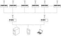
The utility model relates to a multi-motor intelligent servo system, and solves the defects of the motor of the prior art, such as requirement on various special-purpose equipment for monitor and detection, complex system connection and difficulty in coordination control with a corresponding servo driver. The system comprises a plurality of mutually independent motors and control modules of the motors. The control modules are servo driving modules; the servo driving modules are connected with gateway modules; the gateway modules are connected with service terminals; the servo driving modules and the gateway modules are connected in a ZigBee protocol communication way; and the gateway modules and the service terminals are connected through a WiFi communication way. The whole system conducts data transmission through a communication way, and can realize simple remote connection of each equipment and coordination control on the motors and corresponding servo driving modules.
Description
Technical field
The utility model relates to a kind of servo system, especially drives many intelligent motors servo system of multiple electric motors with communication modes transfer instruction and control.
Background technology
Internet of Things (The Internet of things) is the information-based new model of using, pass through radio-frequency (RF) identification, information sensing equipment such as global positioning system, carry out information exchange and communication, be used for realizing intramundane perception and control, it is considered to the main growth point of message area new round development and the core actuating force of industrial upgrading, be widely used in traffic, household, environmental protection, government affairs, security, fire-fighting, electrical network, the various aspects of industry-by-industry such as food security and national defence and life are the computers that continues, information industry tide again after the Internet and the mobile radio communication.
Drive the basic technology that drags as motor with control technology, be widely used in each industry, motor at various power, type, all kinds of servo-drivers have also been developed on the market accordingly, but there is the strong problem of specificity, different motors needs supporting different driver, expends the production efficiency that great amount of manpower and material resources has reduced enterprise directly or indirectly, and the competitiveness of enterprise on market brought negative effect.
The part servo-driver has designed intelligent control algorithm, and functions such as parameter Selection Floater have made its requirement of satisfying versatility, but for the maintenance of a plurality of drivers itself, arrange and need finish in actual job site, lack unified, management efficiently.
Because the large-size machine price is very expensive, and the loss that the production process interruption brings is often more huge than the loss of motor, so large-size machine is carried out operational monitoring and failure diagnosis, is conducive to avoid the generation of major accident.The various parameters (as humiture, vibrations, noise) of motor operation often need by the special equipment collection as monitoring, the important indicator that detects each parts, and its system connects complicated, and are difficult to and corresponding servo-driver is coordinated control.
Summary of the invention
The purpose of this utility model provides a kind of many intelligent motors servo system, and solving the prior motor operation needs various special equipments to monitor and detect, and system connects complicated, and is difficult to and defective that corresponding servo-driver is coordinated to control.
The technical scheme that its technical problem that solves the utility model adopts is: a kind of many intelligent motors servo system, the control module that comprises many separate motors and multiple electric motors, control module is servo-driven module, servo-driven module is connected with gateway module, gateway module is connected with service terminal, adopt the communication modes of ZigBee agreement to link to each other between servo-driven module and the gateway module, link to each other for the communication modes of WiFi between gateway module and the service terminal.Servo-driven module is mainly used in receiving control command, the parameter setting instruction that sends by gateway module, gathers temperature information, vibration information, current information and the positional information of drive motors, and according to command adapted thereto control motor movement; Service terminal is mainly used in for the user in conjunction with actual production technology, requirement, write, store the motor control command, debug, arrange each servo-driven module parameter, simultaneously, be responsible for the motor service data that receives is carried out analyzing and processing, according to specific algorithm various common equipment faults are diagnosed, and medium-term and long-term state estimation, also to monitor the real electrical machinery running status simultaneously, revise parameter function; Whole system is carried out transfer of data by communication modes, can realize each equipment teleconnexion, connects fairly simplely, and motor and corresponding servo-driven module can be coordinated control.
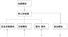
As preferably, servo-driven module comprises core controller, the driver module that links to each other with core controller, information acquisition module, memory module and communication module, and driver module links to each other with each motor.
As preferably, information acquisition module comprises transducer, the filtering and noise reduction unit that links to each other with transducer, the signal amplification unit that links to each other with the filtering and noise reduction unit, and transducer comprises temperature sensor, humidity sensor, vibrating sensor, current sensor and position transducer.Utilize various sensor technologies and wireless network communication technique, can realize the real-time collection to the environmental information in the factory, these information are aggregated into supervising platform, be conducive to administrative staff the environment of plant is carried out real-time monitoring, according to temperature, humidity information, can also control air-conditioning equipment automatically, thereby realize energy-saving and emission-reduction, reduce power consumption.
As preferably, memory module is the ROM memory, and the ROM memory carries out exchanges data by data-address bus and service terminal.
As preferably, communication module is the low-power consumption rf processor, and the low-power consumption rf processor is accepted the gateway module instruction by ZigBee agreement communication modes, and adopts serial communication mode to be sent to core controller.
As preferably, comprise in the driver module that the motor control signal of bridge-type driving chip and power chip and emerging controller exports motor to through bridge-type driving chip and power chip successively.
As preferably, service terminal comprises as the industrial computer of server with as mobile phone and the computer of customer mobile terminal.Adopt the mode of Remote configuration parameter, increased the versatility of drive system and debugging property greatly.
The beneficial effects of the utility model are: whole system is carried out transfer of data by communication modes, can realize each equipment teleconnexion, connects fairly simplely, and motor and corresponding servo-driven module can be coordinated control.
Description of drawings
Fig. 1 is a kind of system configuration schematic diagram of the utility model;
Fig. 2 is a kind of servo-driven module structural representation of the utility model;
Fig. 3 is a kind of power module schematic diagram of the utility model;
Fig. 4 is a kind of information acquisition module schematic diagram of the utility model;
Fig. 5 is a kind of memory module schematic diagram of the utility model;
Fig. 6 is a kind of communication module schematic diagram of the utility model;
Fig. 7 is a kind of driver module signal transmission of the utility model schematic diagram;
Fig. 8 is a kind of gateway module communication of the utility model work schematic diagram.
Embodiment
Below by specific embodiment, and by reference to the accompanying drawings, the technical solution of the utility model is described in further detail.
Embodiment: a kind of many intelligent motors servo system (referring to accompanying drawing 1), the control module that comprises many separate motors and multiple electric motors, control module is servo-driven module, servo-driven module is connected with gateway module, gateway module is connected with service terminal, adopt the communication modes of ZigBee agreement to link to each other between servo-driven module and the gateway module, link to each other for the communication modes of WiFi between gateway module and the service terminal.
Servo-driven module comprises core controller, the driver module that links to each other with core controller, information acquisition module, memory module and communication module, driver module link to each other with each motor (referring to accompanying drawing 2).The arc controller is powered by power module, power module comprises 5V Voltage stabilizing module and 3.3V Voltage stabilizing module (referring to accompanying drawing 3), the 18-36V DC power supply of input is through 5V Voltage stabilizing module output 5V voltage, give core controller through 3.3V Voltage stabilizing module output 3.3V voltage then, information acquisition module comprises transducer, the filtering and noise reduction unit that links to each other with transducer, the signal amplification unit (referring to accompanying drawing 4) that links to each other with the filtering and noise reduction unit, and transducer comprises temperature sensor, humidity sensor, vibrating sensor, current sensor and position transducer.Transducer output transducer information by filtering, denoising unit, and then through signal amplification unit, inputs to core controller with 2.5V a reference source.Memory module is the ROM memory, the ROM memory carries out exchanges data (referring to accompanying drawing 5) by data-address bus and service terminal, user configured various parameter exports the ROM memory to by data address bus, by data address bus the parameter of preserving is read during the servo-driven module initialization again.Communication module is the low-power consumption rf processor, and the low-power consumption rf processor is accepted the gateway module instruction by ZigBee agreement communication modes, and adopts serial communication mode to be sent to core controller (referring to accompanying drawing 6).The motor control signal that comprises bridge-type driving chip and power chip and emerging controller in the driver module exports motor (referring to accompanying drawing 7) to through bridge-type driving chip and power chip successively.The low-power consumption rf processor receives various controls, configuration-direct that service terminal sends by the WiFi communication, resolves the back and is sent to corresponding servo-driven module by ZigBee agreement communication modes.
Service terminal comprises as the industrial computer of server with as mobile phone and the computer of customer mobile terminal.
Above-described embodiment is a kind of preferred version of the present utility model, is not the utility model is done any pro forma restriction, also has other variant and remodeling under the prerequisite that does not exceed the technical scheme that claim puts down in writing.
Claims (7)
1. intelligent motor servo system more than a kind, the control module that comprises many separate motors and multiple electric motors, it is characterized in that control module is servo-driven module, servo-driven module is connected with gateway module, gateway module is connected with service terminal, adopt the communication modes of ZigBee agreement to link to each other between servo-driven module and the gateway module, link to each other for the communication modes of WiFi between gateway module and the service terminal.
2. many intelligent motors servo system according to claim 1, it is characterized in that servo-driven module comprises core controller, the driver module that links to each other with core controller, information acquisition module, memory module and communication module, driver module links to each other with each motor.
3. many intelligent motors servo system according to claim 2, it is characterized in that the filtering and noise reduction unit that information acquisition module comprises transducer, links to each other with transducer, the signal amplification unit that links to each other with the filtering and noise reduction unit, transducer comprises temperature sensor, humidity sensor, vibrating sensor, current sensor and position transducer.
4. many intelligent motors servo system according to claim 2 is characterized in that memory module is the ROM memory, and the ROM memory carries out exchanges data by data-address bus and service terminal.
5. many intelligent motors servo system according to claim 2, it is characterized in that communication module is the low-power consumption rf processor, the low-power consumption rf processor is accepted the gateway module instruction by ZigBee agreement communication modes, and adopts serial communication mode to be sent to core controller.
6. according to claim 2 or 3 or 4 or 5 described many intelligent motors servo systems, it is characterized in that the motor control signal that comprises bridge-type driving chip and power chip and emerging controller in the driver module exports motor to through bridge-type driving chip and power chip successively.
7. according to claim 1 or 2 or 3 or 4 or 5 described many intelligent motors servo systems, it is characterized in that service terminal comprises as the industrial computer of server with as mobile phone and the computer of customer mobile terminal.
Priority Applications (1)
| Application Number | Priority Date | Filing Date | Title |
|---|---|---|---|
| CN201320070709XU CN203151411U (en) | 2013-02-07 | 2013-02-07 | Multi-motor intelligent servo system |
Applications Claiming Priority (1)
| Application Number | Priority Date | Filing Date | Title |
|---|---|---|---|
| CN201320070709XU CN203151411U (en) | 2013-02-07 | 2013-02-07 | Multi-motor intelligent servo system |
Publications (1)
| Publication Number | Publication Date |
|---|---|
| CN203151411U true CN203151411U (en) | 2013-08-21 |
Family
ID=48978902
Family Applications (1)
| Application Number | Title | Priority Date | Filing Date |
|---|---|---|---|
| CN201320070709XU Expired - Fee Related CN203151411U (en) | 2013-02-07 | 2013-02-07 | Multi-motor intelligent servo system |
Country Status (1)
| Country | Link |
|---|---|
| CN (1) | CN203151411U (en) |
Cited By (3)
| Publication number | Priority date | Publication date | Assignee | Title |
|---|---|---|---|---|
| CN103645719A (en) * | 2013-12-18 | 2014-03-19 | 江苏大学 | Multi-motor synchronous remote control system |
| CN105320063A (en) * | 2015-04-20 | 2016-02-10 | 重庆有法数控设备有限责任公司 | Novel intelligent monitoring system of servo driver |
| CN110365256A (en) * | 2019-06-29 | 2019-10-22 | 青岛海瑞智能工程有限公司 | A kind of intelligent motor controller and its supporting body |
-
2013
- 2013-02-07 CN CN201320070709XU patent/CN203151411U/en not_active Expired - Fee Related
Cited By (4)
| Publication number | Priority date | Publication date | Assignee | Title |
|---|---|---|---|---|
| CN103645719A (en) * | 2013-12-18 | 2014-03-19 | 江苏大学 | Multi-motor synchronous remote control system |
| CN103645719B (en) * | 2013-12-18 | 2016-12-07 | 江苏大学 | A kind of multi-drive synchronization tele-control system |
| CN105320063A (en) * | 2015-04-20 | 2016-02-10 | 重庆有法数控设备有限责任公司 | Novel intelligent monitoring system of servo driver |
| CN110365256A (en) * | 2019-06-29 | 2019-10-22 | 青岛海瑞智能工程有限公司 | A kind of intelligent motor controller and its supporting body |
Similar Documents
| Publication | Publication Date | Title |
|---|---|---|
| CN102692912B (en) | Onsite-level low-cost redundancy measuring and controlling network based on wired and wireless hot spare redundancy communication | |
| CN202737890U (en) | Low-cost on-site measurement and control gateway module of wired and wireless hot standby redundancy communication | |
| CN103545924A (en) | Secondary equipment state online monitoring method | |
| CN203520139U (en) | ZigBee-based intelligent diagnosis system for cluster motor fault | |
| CN104898525A (en) | Data acquisition device, data acquisition system and data acquisition method | |
| CN203151411U (en) | Multi-motor intelligent servo system | |
| CN106230376A (en) | A kind of Power Line Inspection System based on the Big Dipper | |
| CN104881008A (en) | Remote monitoring system based on Internet-of-Things | |
| CN205353751U (en) | Train network system | |
| CN202583833U (en) | Multi-motor intelligent servo system based on internet of things technology | |
| CN106230122A (en) | A kind of power equipment safety monitoring system based on wireless network | |
| CN202735735U (en) | Low-cost on-site measurement and control I/O module of wired and wireless hot standby redundancy communication | |
| CN202772610U (en) | Monitoring system for battery management systems of electric vehicles | |
| CN103730960A (en) | Electric power supply system communication system and communication method thereof | |
| CN203588061U (en) | PLC-based automatic control system for waterworks | |
| RU165005U1 (en) | MONITORING TERMINAL | |
| CN203453027U (en) | Safe intelligent control system for air compressors | |
| CN211554725U (en) | Remote monitoring system for operation state of book and periodical machine | |
| CN107945496A (en) | A kind of data acquisition monitoring system based on intelligent electric meter | |
| CN203929877U (en) | A kind of wireless real time monitoring system | |
| CN203206273U (en) | Motor monitoring system based on CAN bus | |
| CN103226340A (en) | Programmable logic controller and realization method | |
| CN202886920U (en) | Elasticizer control system | |
| CN203376605U (en) | Numerical control machine tool robot real-time operation monitoring system | |
| CN104537828A (en) | Device for detecting carrier communication in power consumption information collection device |
Legal Events
| Date | Code | Title | Description |
|---|---|---|---|
| C14 | Grant of patent or utility model | ||
| GR01 | Patent grant | ||
| C17 | Cessation of patent right | ||
| CF01 | Termination of patent right due to non-payment of annual fee |
Granted publication date: 20130821 Termination date: 20140207 |