CN203110914U - Passenger car headstock air inlet structure - Google Patents
Passenger car headstock air inlet structure Download PDFInfo
- Publication number
- CN203110914U CN203110914U CN 201320016025 CN201320016025U CN203110914U CN 203110914 U CN203110914 U CN 203110914U CN 201320016025 CN201320016025 CN 201320016025 CN 201320016025 U CN201320016025 U CN 201320016025U CN 203110914 U CN203110914 U CN 203110914U
- Authority
- CN
- China
- Prior art keywords
- wind
- grid
- grille
- guiding section
- manned vehicle
- Prior art date
- Legal status (The legal status is an assumption and is not a legal conclusion. Google has not performed a legal analysis and makes no representation as to the accuracy of the status listed.)
- Expired - Fee Related
Links
Images
Abstract
The utility model discloses a passenger car headstock air inlet structure. An upper grid (2) and a lower grid (3) are arranged on a front bumper (1), the upper grid (2) is arranged above the lower grid (3), a left flow guide plate (4) and a right flow guide plate (5) are further arranged in the front bumper (1), the left flow guide plate (4) is arranged at the left end of the upper grid and the lower end of the lower grid, the right flow guide plate (5) is arranged at the right end of the upper grid and the right end of the lower grid, an upper flow guide (6) is arranged at the back of the upper grid (2) in the horizontal direction, a lower flow guide plate (7) is arranged at the bottom of the back of the lower grind (3) in the horizontal direction, and a square shape is defined by the upper flow guide plate (6), the lower flow guide plate (7), the upper grid (2) and the lower grid (3). The passenger car headstock air inlet structure can guide air entering the upper grid and the lower grid to flow to a condenser and a radiator, guarantees radiation efficiency of the condenser and the radiator, effectively prevents air eddy from generating and greatly improves utilization rate of output power of an engine.
Description
Technical field
The utility model belongs to automobile technical field, specifically, and the particularly gas flow guiding structure of manned vehicle headstock.
Background technology
The front bumper of manned vehicle headstock is provided with upper and lower grid, and when manned vehicle travelled, air entered machinery space by upper and lower grid, and condenser and radiator are carried out the air cooling type heat radiation.The deficiency of existing structure is:
1) go up grid horizontal bar because the needs of processing technology, generally be acclivitous, so when manned vehicle travels, the air inlet of last grid is flowed from low to high, has air-flow greatly like this and flows away from the head of condenser and radiator, and this part air-flow does not pass through condenser and radiator, thereby can influence the effect of heat radiation, particularly, position less at last grid leaned on, and when perhaps the speed of a motor vehicle is very fast, shows particularly evident.
2) air-flow that grid enters on directly is flushed on the machinery space plate greatly, the air-flow that Under The Grille enters directly is flushed on the engine lower guard board greatly, can in machinery space, produce eddy current, reduced the air cooling effect to condenser and radiator on the one hand, on the other hand, increase the resistance that manned vehicle travels, reduced the degree of utilization of engine output.
The utility model content
Technical problem to be solved in the utility model is to provide a kind of manned vehicle headstock air intake structure, with the radiating efficiency of effective raising condenser and radiator.
The technical solution of the utility model is as follows: a kind of manned vehicle headstock air intake structure, front bumper (1) is provided with grid (2) and Under The Grille (3), last grid (2) is positioned at the top of Under The Grille (3), in described front bumper (1), also be provided with left deflecting plate (4) and right deflecting plate (5), left side deflecting plate (4) is positioned at, the left end of Under The Grille, right deflecting plate (5) is positioned at, the right-hand member of Under The Grille, the rear of grid (2) is horizontally arranged with baffle upper plate (6) on described, the bottom at Under The Grille (3) rear is along laterally being provided with chin spoiler (7), described baffle upper plate (6), chin spoiler (7), last grid (2) and Under The Grille (3) are encircled into " mouth " font.
The utility model is on the basis of original left deflecting plate and right deflecting plate, baffle upper plate and chin spoiler have been set up, and make four deflecting plates form the distribution of " mouth " font, four deflecting plate combineds action, play water conservancy diversion, air pilot flow direction condenser and radiator that upper and lower grid is entered, to avoid air-flow to flow away from the head of condenser and radiator, guaranteed that basic all air-flows all pass through condenser and radiator so on the one hand, thereby improved the radiating efficiency of condenser and radiator greatly, eliminated the not enough disadvantage of dispelling the heat; On the other hand, can reduce the generation of air whirl, correspondingly reduce the resistance that manned vehicle travels, effectively improve the degree of utilization of engine output.
The bottom of described baffle upper plate (6) is made up of wind-guiding section (6b) on the wind-guiding section (6a) and second on first, on first on the lower end and second of wind-guiding section (6a) upper end of wind-guiding section (6b) be connected as a single entity, and on first the inclination angle (a) of wind-guiding section (6a) and horizontal surface greater than the inclination angle (b) of wind-guiding section (6b) on second with horizontal surface.Moulding is simple on the one hand for above structure, and processing and fabricating is easy, and cost is low; On the other hand, can further reduce the air intake resistance, avoid eddy current to produce, and guaranteed the water conservancy diversion effect.
As preferably, wind-guiding section (6a) be 70-80 ° with the inclination angle (a) of horizontal surface on described first, and the inclination angle (b) of wind-guiding section (6b) and horizontal surface is 50-60 ° on second.
In order to increase structural strength, prevent that baffle upper plate from deforming or damage, at the back side of described baffle upper plate (6) along laterally being formed with first reinforced rib (6c), the preceding high back low dip setting of this first reinforced rib (6c).
The end face of described chin spoiler (7) is following wind-guiding face (7a), the preceding high back low dip setting of this time wind-guiding face (7a).Above structure can be avoided dispersing downwards from the air-flow that Under The Grille enters, and directly rushes at engine lower guard board and produces eddy current, has effectively guaranteed the effect of water conservancy diversion simultaneously.
As preferably, described wind-guiding face (7a) down is 12-20 ° with the angle of horizontal surface.
In order to increase structural strength, prevent that chin spoiler from deforming or damage, along laterally being formed with second reinforced rib (7b), this second reinforced rib (7b) is basically perpendicular to down wind-guiding face (7a) on the bottom surface of described chin spoiler (7).
Beneficial effect: air pilot flow direction condenser and radiator that the utility model can enter upper and lower grid, both guaranteed the radiating efficiency of condenser and radiator, effectively avoided the generation of air whirl again, improve the degree of utilization of engine output greatly, had characteristics such as design is ingenious, simple in structure, transformation is easy, improvement cost is low, applied widely.
Description of drawings
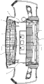
Fig. 1 is structural representation of the present utility model.
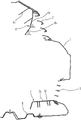
Fig. 2 is the A-A cutaway view of Fig. 1.
The specific embodiment
The utility model is described in further detail below in conjunction with drawings and Examples:
As shown in Figure 1 and Figure 2, the utility model is made of front bumper 1, last grid 2, Under The Grille 3, left deflecting plate 4, right deflecting plate 5, baffle upper plate 6 and chin spoiler 7 etc.Wherein, front bumper 1 is installed on the head of manned vehicle, and front bumper 1 is provided with grid 2 and Under The Grille 3, and last grid 2 is positioned at the top of Under The Grille 3; Also be provided with left deflecting plate 4 and right deflecting plate 5 in described front bumper 1, left deflecting plate 4 is positioned at upper and lower grid 2,3 left end, and right deflecting plate 5 is positioned at upper and lower grid 2,3 right-hand member.The arrangement form of described front bumper 1, last grid 2, Under The Grille 3, left deflecting plate 4 and right deflecting plate 5 is same as the prior art, does not give unnecessary details at this.
As shown in Figure 1 and Figure 2, be horizontally arranged with baffle upper plate 6 at the rear of last grid 2, this baffle upper plate 6 is fixedly mounted on grid 2 or the front bumper 1.The bottom of described baffle upper plate 6 is made up of wind-guiding section 6b on the wind-guiding section 6a and second on first, on first on the lower end and second of wind-guiding section 6a the upper end of wind-guiding section 6b be connected as a single entity, and on first on the wind-guiding section 6a and second wind-guiding section 6b be positioned at the rear side of grid 2 ventilation inlets.The inclination angle a of wind-guiding section 6a and horizontal surface is greater than the inclination angle b of wind-guiding section 6b on second and horizontal surface on described first, and the inclination angle a of wind-guiding section 6a and horizontal surface is 70-80 ° on first, and the inclination angle b of wind-guiding section 6b and horizontal surface is 50-60 ° on second.In order to increase structural strength, laterally be formed with many first reinforced rib 6c on the edge, the back side of described baffle upper plate 6, high back low dip setting before this first reinforced rib 6c, and be parallel to each other between the first reinforced rib 6c.
As shown in Figure 1 and Figure 2, laterally be provided with chin spoiler 7 on the edge, bottom at Under The Grille 3 rears, this chin spoiler 7 is positioned at last the place ahead of engine lower guard board 8, and chin spoiler 7 is fixedly mounted on Under The Grille 3 or the front bumper 1.The end face of described chin spoiler 7 is following wind-guiding face 7a, high before this time wind-guiding face 7a after the low dip setting, the angle of following wind-guiding face 7a and horizontal surface is 12-20 °.In order to increase structural strength, along laterally being formed with many second reinforced rib 7b, this second reinforced rib 7b is basically perpendicular to down wind-guiding face 7a on the bottom surface of chin spoiler 7.Described baffle upper plate 6, chin spoiler 7, last grid 2 and Under The Grille 3 are encircled into " mouth " font, four deflecting plate combineds action, play water conservancy diversion, air pilot flow direction condenser and radiator (not drawing among the figure) that upper and lower grid 2,3 is entered, improving the radiating efficiency of condenser and radiator, and reduce the generation of air whirl.
Claims (7)
1. manned vehicle headstock air intake structure, front bumper (1) is provided with grid (2) and Under The Grille (3), last grid (2) is positioned at the top of Under The Grille (3), in described front bumper (1), also be provided with left deflecting plate (4) and right deflecting plate (5), left side deflecting plate (4) is positioned at, the left end of Under The Grille, right deflecting plate (5) is positioned at, the right-hand member of Under The Grille, it is characterized in that: the rear of grid (2) is horizontally arranged with baffle upper plate (6) on described, the bottom at Under The Grille (3) rear is along laterally being provided with chin spoiler (7), described baffle upper plate (6), chin spoiler (7), last grid (2) and Under The Grille (3) are encircled into " mouth " font.
2. manned vehicle headstock air intake structure according to claim 1, it is characterized in that: the bottom of described baffle upper plate (6) is made up of wind-guiding section (6b) on the wind-guiding section (6a) and second on first, on first on the lower end and second of wind-guiding section (6a) upper end of wind-guiding section (6b) be connected as a single entity, and on first the inclination angle (a) of wind-guiding section (6a) and horizontal surface greater than the inclination angle (b) of wind-guiding section (6b) on second with horizontal surface.
3. manned vehicle headstock air intake structure according to claim 2 is characterized in that: wind-guiding section (6a) be 70-80 ° with the inclination angle (a) of horizontal surface on described first, and the inclination angle (b) of wind-guiding section (6b) and horizontal surface is 50-60 ° on second.
4. according to claim 1 or 2 or 3 described manned vehicle headstock air intake structures, it is characterized in that: the edge, the back side at described baffle upper plate (6) laterally is formed with first reinforced rib (6c), the preceding high back low dip setting of this first reinforced rib (6c).
5. manned vehicle headstock air intake structure according to claim 1 is characterized in that: the end face of described chin spoiler (7) is wind-guiding face (7a) down, the preceding high low dip setting afterwards of this time wind-guiding face (7a).
6. manned vehicle headstock air intake structure according to claim 5 is characterized in that: described wind-guiding face (7a) down is 12-20 ° with the angle of horizontal surface.
7. according to claim 5 or 6 described manned vehicle headstock air intake structures, it is characterized in that: along laterally being formed with second reinforced rib (7b), this second reinforced rib (7b) is basically perpendicular to down wind-guiding face (7a) on the bottom surface of described chin spoiler (7).
Priority Applications (1)
| Application Number | Priority Date | Filing Date | Title |
|---|---|---|---|
| CN 201320016025 CN203110914U (en) | 2013-01-11 | 2013-01-11 | Passenger car headstock air inlet structure |
Applications Claiming Priority (1)
| Application Number | Priority Date | Filing Date | Title |
|---|---|---|---|
| CN 201320016025 CN203110914U (en) | 2013-01-11 | 2013-01-11 | Passenger car headstock air inlet structure |
Publications (1)
| Publication Number | Publication Date |
|---|---|
| CN203110914U true CN203110914U (en) | 2013-08-07 |
Family
ID=48891289
Family Applications (1)
| Application Number | Title | Priority Date | Filing Date |
|---|---|---|---|
| CN 201320016025 Expired - Fee Related CN203110914U (en) | 2013-01-11 | 2013-01-11 | Passenger car headstock air inlet structure |
Country Status (1)
| Country | Link |
|---|---|
| CN (1) | CN203110914U (en) |
Cited By (3)
| Publication number | Priority date | Publication date | Assignee | Title |
|---|---|---|---|---|
| CN103043020A (en) * | 2013-01-11 | 2013-04-17 | 力帆实业(集团)股份有限公司 | Guide structure for passenger vehicle head |
| CN104494420A (en) * | 2014-11-30 | 2015-04-08 | 华晨汽车集团控股有限公司 | Vehicle engine compartment air inlet with air guide plates |
| CN108162744A (en) * | 2017-12-26 | 2018-06-15 | 奇瑞商用车(安徽)有限公司 | A kind of refrigerating module wind deflector |
-
2013
- 2013-01-11 CN CN 201320016025 patent/CN203110914U/en not_active Expired - Fee Related
Cited By (4)
| Publication number | Priority date | Publication date | Assignee | Title |
|---|---|---|---|---|
| CN103043020A (en) * | 2013-01-11 | 2013-04-17 | 力帆实业(集团)股份有限公司 | Guide structure for passenger vehicle head |
| CN103043020B (en) * | 2013-01-11 | 2015-09-30 | 力帆实业(集团)股份有限公司 | Guide structure for passenger vehicle head |
| CN104494420A (en) * | 2014-11-30 | 2015-04-08 | 华晨汽车集团控股有限公司 | Vehicle engine compartment air inlet with air guide plates |
| CN108162744A (en) * | 2017-12-26 | 2018-06-15 | 奇瑞商用车(安徽)有限公司 | A kind of refrigerating module wind deflector |
Similar Documents
| Publication | Publication Date | Title |
|---|---|---|
| CN2892540Y (en) | Engine cabin auxiliary air inducing radiating device | |
| CN103887459B (en) | Power battery system and electric automobile comprising same | |
| CN203110914U (en) | Passenger car headstock air inlet structure | |
| CN103043020B (en) | Guide structure for passenger vehicle head | |
| CN209191684U (en) | Air guide structure and vehicle | |
| CN201825170U (en) | Protecting hood for oil tank of motorcycle | |
| CN101941487B (en) | Motorcycle oil tank shield | |
| CN112103612A (en) | Antenna for communication in motion | |
| CN208364243U (en) | Automotive air intake auxiliary device | |
| CN105564221A (en) | Heat-dissipation air channel structure of power compartment and engineering vehicle | |
| CN206086358U (en) | Initiative intake grille device of car | |
| CN203920920U (en) | A kind of automobile engine cover heat abstractor | |
| CN203666809U (en) | Motor vehicle front wheel air turbulence device | |
| CN207809297U (en) | A kind of air-inlet grille for automobile structure | |
| CN204088525U (en) | A kind of automobile power cell group radiator structure | |
| CN203615809U (en) | Flow guide device of heat radiator | |
| CN203996076U (en) | Machinery space bottom guard plate and the automobile with ventilation function | |
| CN104443072A (en) | Flow guiding plate designing method and flow guiding plate structure designed with the same | |
| CN211731029U (en) | Automobile accessory radiator right lower guide plate assembly | |
| CN205632097U (en) | Aviation baffle mounting structure on radiator | |
| CN209546195U (en) | Regenerative braking energy feedback system converter cabinet radiator | |
| CN211765386U (en) | Bumper grid wind-guiding structure | |
| CN208774896U (en) | With the EVA type electric vehicle body structure for reducing windage | |
| CN205202716U (en) | Scattered hot air duct structure of piggyback pod and engineering vehicle | |
| CN206217796U (en) | Engine lower guard board and vehicle |
Legal Events
| Date | Code | Title | Description |
|---|---|---|---|
| C14 | Grant of patent or utility model | ||
| GR01 | Patent grant | ||
| CF01 | Termination of patent right due to non-payment of annual fee |
Granted publication date: 20130807 Termination date: 20160111 |