CN203109644U - Automatic clamping device for milling crankshaft key groove - Google Patents
Automatic clamping device for milling crankshaft key groove Download PDFInfo
- Publication number
- CN203109644U CN203109644U CN 201320106238 CN201320106238U CN203109644U CN 203109644 U CN203109644 U CN 203109644U CN 201320106238 CN201320106238 CN 201320106238 CN 201320106238 U CN201320106238 U CN 201320106238U CN 203109644 U CN203109644 U CN 203109644U
- Authority
- CN
- China
- Prior art keywords
- base plate
- connecting rod
- rod neck
- clamping device
- support
- Prior art date
- Legal status (The legal status is an assumption and is not a legal conclusion. Google has not performed a legal analysis and makes no representation as to the accuracy of the status listed.)
- Expired - Fee Related
Links
Images


Landscapes
- Jigs For Machine Tools (AREA)
Abstract
The utility model relates to an automatic clamping device for milling a crankshaft key groove. A right pressing bottom plate, a left pressing bottom plate and a pre-supporting bottom plate are mounted on a base of the automatic clamping device, a turning cylinder is mounted on the right pressing bottom plate, a V-shaped supporting block is mounted on the left pressing bottom plate, and the upper end of the turning cylinder is correspondingly connected with a right pressing arm and a left pressing arm. The left pressing bottom plate is further provided with a connecting rod neck limiting block, a connecting rod neck pressing block supporting arm is fixed on the left pressing arm, and a connecting rod neck pressing block is arranged on the connecting rod neck pressing block supporting arm. A pre-supporting cylinder is arranged on the pre-supporting bottom plate and provided with a V-shaped pre-supporting block. The automatic clamping device is simple in structure and convenient to use, the supporting and locating mode of the automatic clamping device can be adjusted according to the length of a crankshaft to be machined, locating and pressing are reliable, the neck of the crankshaft can be effectively prevented from being damaged, and the automatic clamping device is ideal for milling the crankshaft key groove.
Description
Technical field
The utility model relates to a kind of fraise jig of mechanical field, specifically a kind of crankshaft key slot automatic clamping device that mills.
Background technology
During the machining crankshafts keyway, normally the trunnion with bent axle is supported on the V-block on milling machine, and turning crankshaft leans against on the reference column connecting rod neck of bent axle, compresses bent axle then.Commonly used mill the crankshaft key slot clamping device and have following two kinds: a kind of is that V-block and locating piece directly are fixed on the workbench of milling machine, compress with bolt and pressing plate, this weak point that compresses mode is: compress that length consuming time, operator's labour intensity are big, the big or small bad control of thrust, the location of crank-shaft link neck on reference column is unreliable.Another structure is that V-block and locating piece are fixed on the clamp body, compress with bolt and pressing plate, perhaps use cylinder or hydraulic cylinder to compress automatically, this mode that compresses also has weak point: V-block and locating piece are fixed on the position relative fixed on the clamp body, the bent axle that can only adapt to a kind of length, the processing versatility is poor, also has the insecure problem in the location of crank-shaft link neck on reference column simultaneously.In addition because in, large-scale bent axle is heavier, so on the V-block that bent axle directly is put into rigidity the time, more than two kinds of structures axle journal of damaging easily.
Summary of the invention
Technical problem to be solved in the utility model is to overcome the deficiencies in the prior art, provide a kind of simple in structure, easy to use, support, locate and to adjust according to the length of required machining crankshafts, and the location, compress reliable, the crankshaft journal of avoiding damaging mill the crankshaft key slot automatic clamping device.
The technical scheme in the invention for solving the above technical problem is: a kind of crankshaft key slot automatic clamping device that mills, it is characterized in that: it is provided with base, be equipped with on the base right side compress base plate, a left side compress base plate and be positioned in the middle of pre-support base plate, the described right side compresses base plate, a left side compresses base plate and supports base plate in advance and is fixed on the T type groove of base by hold-down screw and T type groove nut, the right side compresses base plate, a left side compresses and is separately installed with a corner cylinder and a support V-block on the base plate, and corner cylinder upper end correspondingly is connected with right clamping arm, left clamping arm; A described left side compresses connecting rod neck limited block also is installed on the base plate, and connecting rod neck compact heap support arm is fixedly arranged on the left clamping arm; On the described connecting rod neck compact heap support arm connecting rod neck compact heap is installed; On the described pre-support base plate pre-support cylinder is installed, the pre-support V-block of being made by elastomeric material is installed at this cylinder.
Base described in the utility model is provided with a groove, and the described right side compresses base plate, a left side and compresses the base plate platy structure that is rectangle, and it is identical with the width of this groove with the length that a left side compresses base plate that the right side compresses base plate, and the right side compresses base plate, a left side compresses base plate and is installed in this groove.
Also be provided with three vertical T type grooves in the groove of base described in the utility model.
Right clamping arm described in the utility model, the left clamping arm structure that is rectangle has a square hole at the one end, is fixed on the corner cylinder by hold-down nut.
The rectangular shape of connecting rod neck compact heap support arm described in the utility model has a circular hole on one of them limit, connecting rod neck compact heap is installed in the circular hole, and there is slot the side on another limit, cooperates with slot by hold-down screw to be fixed on the left clamping arm.Be fixed on the connecting rod neck compact heap support arm on the left clamping arm, can adjust front and back position at left clamping arm, make connecting rod neck compact heap aim at crank-shaft link neck.
Connecting rod neck compact heap described in the utility model is the multidiameter shape, and its top is provided with screw thread, and the centre is with spring, and the circular hole on the connecting rod neck compact heap support arm is passed on top, is fixed by hold-down nut and split pin, and middle spring is in the state that compresses in advance.Be fixed on the connecting rod neck compact heap on the connecting rod neck compact heap support arm, can slide up and down by the flexible of spring.
Pre-support cylinder described in the utility model is arranged in the base lower space.
During the utility model clamping bent axle, at first bent axle is lifted on the pre-support V-block of being made by elastomeric material, in pre-support cylinder, feed compressed air then, support under the cylinder drive pre-, bent axle slowly moves down until main bearing journal and drops on the support V-block in company with the pre-V-block that supports.Feed compressed air to the corner cylinder, right clamping arm, left clamping arm and be fixed on connecting rod neck compact heap support arm on the left clamping arm, connecting rod neck compact heap etc. and move downward.In the process of motion, connecting rod neck compact heap at first touches the connecting rod neck of bent axle, and promotes the connecting rod neck around the rotation of the center of bent axle, touches connecting rod neck limited block until the below of connecting rod neck, bent axle and the stop motion of connecting rod neck compact heap, and bent axle is finished the location.Finish in the location process at bent axle, right clamping arm, left clamping arm and connecting rod neck compact heap support arm continue to move downward, and the spring that is sleeved on the connecting rod neck compact heap is compressed, till right clamping arm, left clamping arm compress the trunnion that is supported on the V-block.Against existing technologies, the utility model is simple in structure, and is easy to use, support, locate and to adjust according to the length of required machining crankshafts, and the location, compressing reliably, can effectively avoid the crankshaft journal of damaging, is a kind of desirable crankshaft key slot automatic clamping device that mills.
Description of drawings
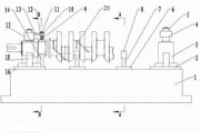
Fig. 1 is the front view that the utility model is formed structure.
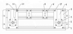
Fig. 2 is vertical view of the present utility model.
Fig. 3 is the right side view of main bearing journal after compacted among Fig. 1.
Fig. 4 is the B-B cutaway view of crank-shaft link neck after compacted among Fig. 1.
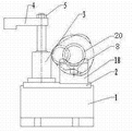
Fig. 5 is that the utility model workpiece is placed on the pre-support V-block, still the lateral plan of malcompression.
Fig. 6 is that workpiece is placed on the pre-support V-block among Fig. 1, the A-A cutaway view when not falling as yet.
Fig. 7 is the zoomed-in view of I portion among Fig. 4.
Label among the figure is: 1. base, 2. the right side compress base plate, 3. the corner cylinder, 4. right clamping arm, 5. hold-down nut, 6. pre-support base plate, 7. pre-support cylinder, 8. pre-support V-block, 9. spring, 10. hold-down nut, 11. split pins, 12. connecting rod neck compact heaps, 13. connecting rod neck compact heap support arms, 14. connecting rod neck limited blocks, 15. left clamping arms, 16. left sides compress base plate, 17. hold-down screws, 18. support V-blocks, 19.T type groove nut, 20. bent axles.
The specific embodiment
Below in conjunction with accompanying drawing the utility model is explained in detail and illustrates.
From Fig. 1, Fig. 2 as can be seen, a kind of crankshaft key slot automatic clamping device that mills, it is provided with base 1, be equipped with on the base right side compress base plate 2, a left side compress base plate 16 and be positioned in the middle of two pre-base plates 6 that support.
The right side described in the utility model compresses base plate 2, a left side compresses and is separately installed with a corner cylinder 3 and a support V-block 18 on the base plate 16.Left and right support V-block 18 is positioned at the below of bent axle 20 trunnions, is used for supporting bent axle.Corner cylinder 3 upper ends correspondingly are connected with right clamping arm 4, left clamping arm 15.Described right clamping arm 4, left clamping arm 15 structure that is rectangle has a square hole at the one end, is fixed on the corner cylinder 3 by hold-down nut 5.
A left side described in the utility model compresses connecting rod neck limited block 14 also is installed on the base plate 16, and connecting rod neck limited block 14 is positioned at the below of bent axle 20 connecting rod necks, is used for limiting the rotational angle that is supported on the bent axle on the support V-block 18.
On the clamping arm 15 of the utility model left side connecting rod neck compact heap support arm 13 is arranged fixedly; On the described connecting rod neck compact heap support arm 13 a connecting rod neck compact heap 12 is installed.Described connecting rod neck compact heap support arm 13 rectangular shapes have a circular hole on one of them limit, connecting rod neck compact heap 12 is installed in the circular hole, and there is slot the side on another limit, cooperates with slot by hold-down screw 17 to be fixed on the left clamping arm 15.Be fixed on the connecting rod neck compact heap support arm 13 on the left clamping arm 15, can adjust front and back position at left clamping arm 15, make connecting rod neck compact heap 12 aim at bent axle 20 connecting rod necks.
Connecting rod neck compact heap 12 described in the utility model is the multidiameter shape, its top is provided with screw thread, just the end at a thinner end has screw thread, the centre is with spring 9, the circular hole on the connecting rod neck compact heap support arm 13 is passed on top, fixing by hold-down nut 10 and split pin 11, middle spring 9 is in the state that compresses in advance.Be fixed on the connecting rod neck compact heap 12 on the connecting rod neck compact heap support arm 13, can slide up and down by the flexible of spring 9, compress the rod journal of bent axle.。As Fig. 4, shown in Figure 7.
The utility model course of work is: be in unclamped state before this clamping device clamping bent axle, right clamping arm 4, left clamping arm 15 and connecting rod neck compact heap 12 upwards lift and turn to the side, as shown in Figure 5 under the effect of corner cylinder 3.Pre-support V-block 8 upwards lifts and is higher than under pre-support cylinder 7 effects and supports V-block 18.During the clamping bent axle, at first bent axle 20 is lifted on the pre-support V-block of being made by elastomeric material 8, in pre-support cylinder 7, feed compressed air then, bent axle is in company with the pre-V-block 8 that supports, support under cylinder 7 drives pre-, slowly move down until main bearing journal and drop on the support V-block 18, as shown in Figure 6.In pre-support cylinder 7, feeding the compressed-air actuated while, feeding compressed air to corner cylinder 3, right clamping arm 4, left clamping arm 15 and be fixed on connecting rod neck compact heap support arm 13 on the left clamping arm 15, connecting rod neck compact heap 12 etc. and move downward.In the process of motion, connecting rod neck compact heap 12 at first touches the connecting rod neck of bent axle, and promotes the connecting rod neck around the rotation of the center of bent axle, touch connecting rod neck limited block 14 until the below of connecting rod neck, bent axle and 12 stop motions of connecting rod neck compact heap, bent axle is finished the location, as shown in Figure 3, Figure 4.Finish in the location process at bent axle, right clamping arm 4, left clamping arm 15 and connecting rod neck compact heap support arm 13 continue to move downward, the spring 9 that is sleeved on the connecting rod neck compact heap 12 is compressed, till right clamping arm 4, left clamping arm 15 compress the trunnion that is supported on the V-block 18, as shown in Figure 3, Figure 4.
Claims (7)
1. one kind is milled the crankshaft key slot automatic clamping device, it is characterized in that: it is provided with base, be equipped with on the base right side compress base plate, a left side compress base plate and be positioned in the middle of pre-support base plate, the described right side compresses base plate, a left side compresses base plate and supports base plate in advance and is fixed on the T type groove of base by hold-down screw and T type groove nut, the right side compresses base plate, a left side compresses and is separately installed with a corner cylinder and a support V-block on the base plate, and corner cylinder upper end correspondingly is connected with right clamping arm, left clamping arm; A described left side compresses connecting rod neck limited block also is installed on the base plate, and connecting rod neck compact heap support arm is fixedly arranged on the left clamping arm; On the described connecting rod neck compact heap support arm connecting rod neck compact heap is installed; On the described pre-support base plate pre-support cylinder is installed, the pre-support V-block of being made by elastomeric material is installed at this cylinder.
2. the crankshaft key slot automatic clamping device that mills according to claim 1, it is characterized in that: described base is provided with a groove, the described right side compresses base plate, a left side and compresses the base plate platy structure that is rectangle, it is identical with the width of this groove with the length that a left side compresses base plate that the right side compresses base plate, and the right side compresses base plate, a left side compresses base plate and is installed in this groove.
3. the crankshaft key slot automatic clamping device that mills according to claim 2 is characterized in that: also be provided with three vertical T type grooves in the groove of described base.
4. the crankshaft key slot automatic clamping device that mills according to claim 1 is characterized in that: described right clamping arm and the left clamping arm structure that is rectangle, at the one end one square hole is arranged, and be fixed on the corner cylinder by hold-down nut.
5. the crankshaft key slot automatic clamping device that mills according to claim 1, it is characterized in that: the rectangular shape of described connecting rod neck compact heap support arm, one circular hole is arranged on one of them limit, connecting rod neck compact heap is installed in the circular hole, there is slot the side on another limit, cooperates with slot by hold-down screw to be fixed on the left clamping arm.
6. the crankshaft key slot automatic clamping device that mills according to claim 1, it is characterized in that: described connecting rod neck compact heap is the multidiameter shape, its top is provided with screw thread, the centre is with spring, the circular hole on the connecting rod neck compact heap support arm is passed on top, fixed by hold-down nut and split pin, middle spring is in the state that compresses in advance.
7. the crankshaft key slot automatic clamping device that mills according to claim 1, it is characterized in that: described pre-support cylinder is arranged in the base lower space.
Priority Applications (1)
| Application Number | Priority Date | Filing Date | Title |
|---|---|---|---|
| CN 201320106238 CN203109644U (en) | 2013-03-08 | 2013-03-08 | Automatic clamping device for milling crankshaft key groove |
Applications Claiming Priority (1)
| Application Number | Priority Date | Filing Date | Title |
|---|---|---|---|
| CN 201320106238 CN203109644U (en) | 2013-03-08 | 2013-03-08 | Automatic clamping device for milling crankshaft key groove |
Publications (1)
| Publication Number | Publication Date |
|---|---|
| CN203109644U true CN203109644U (en) | 2013-08-07 |
Family
ID=48890021
Family Applications (1)
| Application Number | Title | Priority Date | Filing Date |
|---|---|---|---|
| CN 201320106238 Expired - Fee Related CN203109644U (en) | 2013-03-08 | 2013-03-08 | Automatic clamping device for milling crankshaft key groove |
Country Status (1)
| Country | Link |
|---|---|
| CN (1) | CN203109644U (en) |
Cited By (4)
| Publication number | Priority date | Publication date | Assignee | Title |
|---|---|---|---|---|
| CN103111884A (en) * | 2013-03-08 | 2013-05-22 | 天润曲轴股份有限公司 | Automatic clamping device for milling crankshaft key groove |
| CN104070381A (en) * | 2014-06-19 | 2014-10-01 | 安徽埃夫特智能装备有限公司 | Part posture conversion mechanism and method for machining automobile crankshaft |
| CN104625188A (en) * | 2014-12-17 | 2015-05-20 | 中国航空工业集团公司北京航空精密机械研究所 | Method for processing high-symmetry-degree double-key groove of slender shaft component |
| CN105397160A (en) * | 2015-12-18 | 2016-03-16 | 徐勤凤 | Mill-opening equipment for taper pin |
-
2013
- 2013-03-08 CN CN 201320106238 patent/CN203109644U/en not_active Expired - Fee Related
Cited By (9)
| Publication number | Priority date | Publication date | Assignee | Title |
|---|---|---|---|---|
| CN103111884A (en) * | 2013-03-08 | 2013-05-22 | 天润曲轴股份有限公司 | Automatic clamping device for milling crankshaft key groove |
| CN103111884B (en) * | 2013-03-08 | 2015-05-13 | 天润曲轴股份有限公司 | Automatic clamping device for milling crankshaft key groove |
| CN104070381A (en) * | 2014-06-19 | 2014-10-01 | 安徽埃夫特智能装备有限公司 | Part posture conversion mechanism and method for machining automobile crankshaft |
| CN104070381B (en) * | 2014-06-19 | 2016-06-22 | 安徽埃夫特智能装备有限公司 | Part orientation shifter and conversion method thereof for automobile crane processing |
| CN104625188A (en) * | 2014-12-17 | 2015-05-20 | 中国航空工业集团公司北京航空精密机械研究所 | Method for processing high-symmetry-degree double-key groove of slender shaft component |
| CN105397160A (en) * | 2015-12-18 | 2016-03-16 | 徐勤凤 | Mill-opening equipment for taper pin |
| CN106975777A (en) * | 2015-12-18 | 2017-07-25 | 徐勤凤 | Taper bolt milling open device |
| CN105397160B (en) * | 2015-12-18 | 2017-12-12 | 泰州市华丰科技设备有限公司 | Taper bolt milling open device |
| CN106975777B (en) * | 2015-12-18 | 2018-11-16 | 扬州智创企业运营管理服务有限公司 | Taper bolt mills open device |
Similar Documents
| Publication | Publication Date | Title |
|---|---|---|
| CN103111884B (en) | Automatic clamping device for milling crankshaft key groove | |
| CN204771765U (en) | Automobile -used clamping device of hydraulic cylinder cylinder end | |
| CN203109644U (en) | Automatic clamping device for milling crankshaft key groove | |
| CN103659371A (en) | Tool for fast positioning square workpiece | |
| CN103567778B (en) | Fixture | |
| CN204019206U (en) | A kind of five degree of freedom bench vice | |
| CN105149985A (en) | Clamp for processing gearbox body of forklift | |
| CN201309088Y (en) | Fixture of milling machine | |
| CN205021108U (en) | Condenser elasticity nut mounting plate | |
| CN203696531U (en) | Locating and clamping tool for processing front axle support of forklift | |
| CN213224478U (en) | Work fixture | |
| CN211991950U (en) | Watch leadless environment-friendly bismuth-green stainless steel watch case processing device | |
| CN102248484A (en) | Eccentric clamping fixture | |
| CN203636455U (en) | Quick positioning tooling for square workpieces | |
| CN208575284U (en) | A kind of roller part double-faced boring lathe | |
| CN216097640U (en) | Peripheral milling fixture of axle fist portion | |
| CN207087398U (en) | A kind of Multi-axis Machining fixture | |
| CN203156620U (en) | Cylindrical drum workpiece clamping device | |
| CN211564683U (en) | Hydraulic combined punching and shearing machine | |
| CN202169491U (en) | Workpiece milling and tapping bracket clamp | |
| CN202458271U (en) | Polishing workpiece clamping mechanism | |
| CN106736753B (en) | A kind of hydraulic automatic fixture | |
| CN104625808A (en) | Flexible two-point auxiliary supporting device | |
| CN216706788U (en) | Axle housing processingequipment and lathe | |
| CN204868090U (en) | Cantilever positioning fixture of shifting that reverses gear of convenient hoist and mount |
Legal Events
| Date | Code | Title | Description |
|---|---|---|---|
| C14 | Grant of patent or utility model | ||
| GR01 | Patent grant | ||
| CF01 | Termination of patent right due to non-payment of annual fee | ||
| CF01 | Termination of patent right due to non-payment of annual fee |
Granted publication date: 20130807 Termination date: 20160308 |