CN203052857U - PM2.5 purification air-conditioning terminal with special-shaped heat exchanger - Google Patents
PM2.5 purification air-conditioning terminal with special-shaped heat exchanger Download PDFInfo
- Publication number
- CN203052857U CN203052857U CN 201320032964 CN201320032964U CN203052857U CN 203052857 U CN203052857 U CN 203052857U CN 201320032964 CN201320032964 CN 201320032964 CN 201320032964 U CN201320032964 U CN 201320032964U CN 203052857 U CN203052857 U CN 203052857U
- Authority
- CN
- China
- Prior art keywords
- air
- wind
- chamber
- heat exchanger
- new wind
- Prior art date
- Legal status (The legal status is an assumption and is not a legal conclusion. Google has not performed a legal analysis and makes no representation as to the accuracy of the status listed.)
- Expired - Fee Related
Links
Images


Landscapes
- Central Air Conditioning (AREA)
Abstract
The utility model discloses a PM2.5 purification air-conditioning terminal with a special-shaped heat exchanger. The PM2.5 purification air-conditioning terminal comprises a heat exchange refrigeration heating area, a fresh air distribution preheating energy-saving area, an air purification area and a water-adding automatic cleaning area. The heat exchanging refrigeration heating area comprises a heat exchanging air passing channel (9), one end of the heat exchanging air passing channel (9) is connected with a framed type heat exchanger (310), the framed type heat exchanger (310) is in an air passing structure formed by a plurality of plate heat exchangers in an enclosing mode, one end of the air-passing structure is closed, and one end of the air-passing structure is open and points to the heat exchanging air passing channel (9). The four areas respectively achieve a heat exchange refrigeration heating function, a fresh air distribution preheating energy-saving function, an air purification function and a water-adding automatic cleaning function.
Description
Technical field
The utility model relates to the air processor that possesses heat recovery system, specifically refers to a kind of special-shaped heat exchanger PM2.5 purification air-conditioning end.
Background technology
At present, the air conditioner industry prosperity, air-conditioning is of a great variety, yet has following problem:
Existing air-conditioning equipment does not possess new wind dispensing function, only carries out interior circulation, can not carry out outer circulation.
Existing air-conditioning equipment does not possess efficient purification function, and air cleaning is incomplete.
Existing air-conditioning equipment does not possess air heat recovery function, and its amount of power consumption is big, and wastes energy.
Existing air-conditioning equipment filter screen often fails in time to clean and troublesome poeration.
Existing air-conditioning equipment noise pollution is serious.
Heat exchanger in traditional air conditioning terminal all is vertically to be placed in the wind passage, its air intake surface is vertical with wind direction to be placed, in fixing height, its incoming air area is little, heat exchanger effectiveness is low, have only simultaneously the one side contact with wind direction, so when distinguished and admirable pass heat exchanger after, the noise of its generation is very big.
The required indoor sets of all traditional air-conditionings such as original central air-conditioning fan coil, connected central air-conditioning indoor set, the on-hook of domestic air conditioning chamber interior walls and cabinet-type air conditioner, their air-supplies, return air are all finished in the interior space, cause the indoor noise pollution that weight does not wait that has.Because they are all installed with indoor, taken indoor certain space, cause finishing to cooperate difficulty big, reduce indoor room part floor height, also needed to arrange condensate pipe separately, caused installation fee expenses of labour material, because machine in condensate pipe and the part needs hidden installation, cause that then installation period prolongs, if condensed water is revealed, then cause interior decoration to destroy.
The utility model content
The purpose of utility model is to provide a kind of special-shaped heat exchanger PM2.5 purification air-conditioning end, and this air processor can solve following problem: improve the heat exchanger effectiveness of heat exchanger, reduce noise.
Implementation of the present utility model is as follows: special-shaped heat exchanger PM2.5 purification air-conditioning end, comprise that heat exchange crosses the wind passage, heat exchange is crossed wind passage one end and is connected with the frame heat exchanger, the frame heat exchanger be mainly by a plurality of heat-exchangerss of the plate type surround constitute that an end closure, an end opening point to that heat exchange crosses the wind passage cross the wind structure.
Based on above-mentioned, in the utility model, than traditional air conditioning terminal, the present invention replaces with the frame heat exchanger with traditional heat exchanger vertical and wind direction, be specifically: traditional heat exchange section is by outer framework, and the heat exchanger that is arranged in the outer framework constitutes, and the utility model is directly replaced traditional outer framework and heat exchanger with the heat exchanger of a frame, like this, the zone that is positioned at original housing body portion also becomes the part of heat exchanger, in identical volume, increased the area of heat exchange, simultaneously, when air-flow carries out heat exchange, heat exchanger in traditional heat exchange section can be blocked in air intake surface with most of air-flow, these air-flows are blocked after running into above-mentioned outer framework, its flowed energy is consumed, when needing air output big, only way is exactly the power that strengthens blower fan, and the utility model adopts the heat exchanger of above-mentioned frame directly to increase its air-out area, in time the wind in air-out front is blocked the generation sinuous flow, these air-flows that are blocked also can directly flow out by the heat exchanger of side, so than traditional air conditioning terminal, its heat exchanger effectiveness height, air output is big, save the energy of blower fan, because air-out area is big, so the wind speed reduction is more than 20%, with reducing noise.
The air intake surface of at least one heat-exchangers of the plate type becomes included angle A with the wind direction that the wind passage is crossed in heat exchange, and the span of included angle A is: 0 °<included angle A<90 °.Preferential consideration angle is 30 ° or 45 ° or 60 ° or 80 °.In the utility model, the wind direction that heat-exchangers of the plate type is crossed the wind passage with respect to heat exchange is tilting, like this than traditional vertical placement, it is in fixing short transverse, the air intake surface of heat-exchangers of the plate type increases, can further increase its heat exchange area, to reach heat exchange purpose completely.
The frame heat exchanger be shaped as triangular prism or cone or round platform.
The frame heat exchanger be shaped as cylinder.An end opening of wind passage is crossed in the close heat exchange of this cylinder, other end closure, and simultaneously, the wall of this cylinder is made up of heat-exchangers of the plate type.
Also comprise the HE BYP valve, described HE BYP valve is positioned between the adjacent heat-exchangers of the plate type or is embedded in heat-exchangers of the plate type.When needs directly ventilate, can open the HE BYP valve, at this moment, the distinguished and admirable HE BYP valve that directly penetrates enters the next stage processing.When the HE BYP valve is closed, carry out heat exchange process.
The utility model can also solve problem: the purification function in this air processor carries out high purification to new wind and the return air of introducing, can remove cigarette smoke, pellet (particulate matter more than 0.1 micron), pollen, dirt mite and excreta, bacterium, ozone, finishing pollution (formaldehyde, benzene series thing and VOCs etc.) in new wind and the indoor return air, also can discharge negative oxygen ion, thoroughly stop secondary pollution, reach the purpose that indoor air efficient purifies, this equipment can clean high efficiency particulate air automatically according to operation hours.
Abnormity heat exchanger PM2.5 purification air-conditioning end, also comprise new wind air exhausting device, new wind air exhausting device comprises the recuperation of heat chamber that the recuperation of heat filter core is installed in the chamber, the front end in described recuperation of heat chamber be equipped with air draft bypass cavity, rear end be equipped with new wind bypass cavity, left end be equipped with new wind distribution cavity, right-hand member be equipped with the air draft that is communicated with the recuperation of heat chamber simultaneously cross the wind chamber and newly wind cross the wind chamber; Air draft is crossed wind chamber and new wind and is crossed the wind chamber and carry out stacked setting, and air draft is crossed the wind chamber and is positioned at new wind and crosses directly over the wind chamber; Crossing the wind chamber with recuperation of heat chamber and air draft respectively after the air draft bypass cavity introducing indoor exhaust wind is communicated with; New wind distribution cavity is communicated with recuperation of heat chamber and new wind bypass cavity respectively after introducing outdoor new wind, and new wind bypass cavity is crossed the wind chamber with new wind and is communicated with.The integral body of the special-shaped heat exchanger PM2.5 purification air-conditioning end of the utility model setting is placed on outdoor, wherein, new wind air exhausting device is the collecting structure of air exhaust passage and new wind passage, in new wind air exhausting device, play by new wind introduce and the discharge of indoor gas in, adopt the recuperation of heat chamber to carry out the heat exchange recycling, with the new wind of the heat transferred in the air exhaust passage, make new wind receive heat and be delivered to next stage again and possess in the equipment of heat exchanger and carry out energy-efficient heat exchange process.Simultaneously for can fast-refrigerating or heat, in order to reduce windage, do not carry out the heat exchange recycling, increase in the utility model new wind bypass cavity and air draft bypass cavity are arranged, new wind by-passing valve in new wind bypass cavity is opened, then new wind bypass cavity and new wind distribution cavity conducting, because the windage to the recuperation of heat chamber is big, then new wind is preferentially crossed the wind chamber with new wind then by new wind bypass cavity and is communicated with.Enter at last and mix the mixing wind that forms new wind return air in the return air conducting, entering next stage at last handles, in like manner, after the air draft by-passing valve of air draft bypass cavity is opened, because the windage to the recuperation of heat chamber is big, then preferentially by crossing the wind chamber to air draft behind the air draft bypass cavity, wind chamber and outdoor conducting are crossed in air draft, carry out quick pump-down process in air draft.Wherein, the air draft by-passing valve is crossed between the wind chamber at air draft bypass cavity and air draft, and its new wind bypass cavity is between new wind bypass cavity and new wind distribution cavity, and these two valves can be remote-controlled or manually opened according to demand.Based on above-mentioned, the utility model employing air exhaust passage and new wind passage carry out the border transmission airflow in bypass branch, and to constitute the structure of a recuperation of heat, the while can carry out the air feed processing fast according to selection and air draft is handled, and compact conformation is powerful.
Further, for the heat exchange process structure that implementation structure is oversimplified, recuperation of heat filter core described in the utility model is made of some wind passages of crossing crisscross and mutual isolation, and its profile is cuboid; Two seamed edges that the recuperation of heat filter core is relative are connected with the inwall in recuperation of heat chamber and the recuperation of heat chamber are divided into 4 cavitys of isolating mutually, and these 4 cavitys are respectively: upper left chamber, upper right chamber, chamber, bottom right, chamber, lower-left; Upper left chamber is communicated with the chamber, bottom right by the wind passage excessively of recuperation of heat filter core, and upper right chamber is by wind passage and the conducting of chamber, lower-left excessively of recuperation of heat filter core; Upper left chamber is communicated with new wind distribution cavity, and the chamber, lower-left is communicated with the air draft bypass cavity, and the conducting of wind chamber is crossed in upper right chamber and air draft, and the chamber, bottom right is crossed the wind chamber with new wind and is communicated with.Structure by above-mentioned recuperation of heat filter core as can be seen, the utility model adopts the mode of unconventional placement recuperation of heat filter core, the rotation of recuperation of heat filter core is placed, place after soon any one side of recuperation of heat filter core will rotate to an angle, make the recuperation of heat filter core recuperation of heat chamber can be divided into above-mentioned 4 cavitys.To reach the conducting purpose that realizes recuperation of heat filter core opposite face in fixed volume, namely upper left chamber is communicated with the chamber, bottom right by the wind passage excessively of recuperation of heat filter core, and upper right chamber is by wind passage and the conducting of chamber, lower-left excessively of recuperation of heat filter core; Like this, new wind in the new wind distribution cavity can enter the recuperation of heat filter core by upper left chamber, is conducting to new wind by the chamber, bottom right at last and crosses the wind chamber, in like manner, the indoor exhaust wind that the air draft bypass cavity is introduced can enter the recuperation of heat filter core by the chamber, lower-left, is conducting to air draft by upper right chamber at last and crosses the wind chamber and be discharged from.
Further, described new wind distribution cavity is connected with new wind air-inlet cavity; New wind air-inlet cavity is equipped with outdoor new wind air inlet, in the outdoor new wind air inlet new wind high efficiency particulate air is installed, the air intake surface of new wind high efficiency particulate air is provided with the automatic cleaning brush of new wind, is provided with new wind under new wind high efficiency particulate air and the new automatic cleaning brush of wind and cleans drip tray.Because new wind air-inlet cavity is as the device of introducing outdoor new wind, therefore new wind air-inlet cavity can contact a large amount of dusts at its outdoor new wind air inlet place that introduces new wind, therefore, the utility model also increases cleaning structure in outdoor new wind air inlet, realize that control is cleaned automatically, reach regular processing and pollute the purpose in source, wherein preferentially the automatic cleaning brush of new wind is arranged on the air intake surface of new wind high efficiency particulate air.
In the new wind air-inlet cavity blower fan is installed.
Described air draft is crossed the wind chamber and is communicated with the air draft chamber, and air draft is equipped with blower fan in the chamber.
Crossing in the wind chamber in new wind air-inlet cavity and air draft increases blower fan, can make wind speed strengthen, and can carry out air draft and fresh air supply fast.
Described new wind is crossed the wind chamber and is communicated with the return air chamber, is provided with the outdoor air exhaust passage in the communication chamber in the return air chamber, and outdoor air exhaust passage is communicated with the air draft bypass cavity.Based on said structure, the utility model also increases the return air chamber, makes indoor return air mix with new wind, improves the heat of new wind, to reach the load purpose that reduces the later stage heat exchanger.Based on said structure, air intake of the present utility model is handled the position, be provided with the return air channel in the equal communication chamber in two ends, and an end and the new wind passage that outdoorly is communicated with, an end is communicated with return air channel, also comprise an end and indoorly be communicated with, an end and the outdoor air exhaust passage that is communicated with, air exhaust passage, new wind passage carry out recuperation of heat in the recuperation of heat filter core.Return air channel is the lower structures of return air chamber and later stage carrying out heat exchange process.
Described return air chamber is communicated with and purifies the heat exchange process cavity.Purifying the heat exchange process cavity can carry out heat exchange and purified treatment to the mixing wind of return air and new wind formation, comprises the air-treatment structure of conventional air-conditioning device.But the air-treatment structure of general air-conditioner does not possess air purification function efficiently, and automatic cleaning function, therefore the utility model adopts following structures as purifying heat exchange process equipment, to reach purification, heat exchange, automatic comprehensive function purpose of cleaning.Concrete structure is as follows.
Purify the heat exchange process cavity and comprise that heat exchange crosses wind passage and blower fan air intake wind chamber, the frame heat exchanger is crossed between wind passage and the blower fan air intake wind chamber in heat exchange.
Heat exchange is crossed to be provided with in the wind passage and is mixed wind high efficiency particulate air, UV fluorescent tube, nano-photo catalytic net, active carbon filter screen; The air intake surface of described mixed wind high efficiency particulate air is provided with and mixes wind automatic water jetting cleaning brush, mix wind high efficiency particulate air, UV fluorescent tube, nano-photo catalytic net, active carbon filter screen under be provided with and mix the wind drip tray; Mixed wind high efficiency particulate air and heat exchange are crossed and also are provided with the high efficiency particulate air by-passing valve between the wind vias inner walls, and the high efficiency particulate air by-passing valve is equipped with Electrostatic Absorption.
Blower fan air intake wind chamber is communicated with the indoor exhaust wind chamber, and blower fan air intake wind is equipped with the humidification atomising device in the chamber, and blower fan and negative oxygen ion generator are installed in the indoor exhaust wind chamber.
Above-mentioned mixed wind high efficiency particulate air, UV fluorescent tube, nano-photo catalytic net, the active carbon filter screen of mentioning carries out air filtration and purification function.The frame heat exchanger carries out hot-swap feature.Be provided with mixed wind drip tray and mixed wind automatic water jetting cleaning brush and can carry out cleaning treatment to mixing the wind high efficiency particulate air.Simultaneously again on this basis, the utility model also increases the high efficiency particulate air by-passing valve, when the needs fast-refrigerating or when heating, opens the high efficiency particulate air by-passing valve, make that mixing wind energy arrives frame heat exchanger place fast, to carry out cooling and warming fast, to play reducing the purpose of windage, simultaneously, in order to carry out fresh air supply fast, therefore, can open the HE BYP valve, mix like this wind can be fast zone by the frame heat exchanger directly supply to indoor.
Blower fan air intake wind chamber is communicated with the indoor exhaust wind chamber, and blower fan and negative oxygen ion generator are installed in the indoor exhaust wind chamber.The increase negative oxygen ion generator can improve the negative oxygen ion number in the room air, through discovering that negative oxygen ion generator is installed in the survival that other zones in the device of the utility model design are unfavorable for negative oxygen ion, therefore, preferentially be arranged in the indoor exhaust wind chamber.
Advantage of the present utility model is: one, air-conditioner only stays an air outlet and return air inlet and exhaust outlet indoor, and new wind dispensing is arranged, and also guarantees the absolute cleaning of room air in the new wind of dispensing, stops secondary pollution, and is more energy-conservation.Two, the purification function in this air processor carries out high purification to new wind and the return air of introducing, cigarette smoke, pellet (particulate matter more than 0.1 micron), pollen, dirt mite and excreta, bacterium, ozone, finishing pollution (formaldehyde, benzene series thing and VOCs etc.) in new wind and the indoor return air can be removed, also negative oxygen ion can be discharged.Thoroughly stop secondary pollution, reach efficient purification.Three, reduce power consumption, energy-conserving and environment-protective.Four, multi-functionization of one, energy savings.Five, be installed on outdoorly, take leave of the inconvenience that condensed water brings, save the interior space and floor height, do not influence finishing difficulty and effect.
Description of drawings
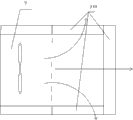
Fig. 1 is the structural representation of special-shaped heat exchanger PM2.5 purification air-conditioning end.
Fig. 2 is the southeastern direction perspective view that new wind air exhausting device adds the return air chamber.
Fig. 3 is the plan structure schematic diagram that new wind air exhausting device adds the return air chamber.
Fig. 4 is the southwestward perspective view that new wind air exhausting device adds the return air chamber.
Fig. 5 is that the structure partition figure that wind chamber and new wind are crossed wind chamber, air draft bypass cavity is crossed in air draft.
Fig. 6 is A-A tangent plane schematic diagram among Fig. 2.
Fig. 7 is the structural representation that purifies the heat exchange process cavity.
Fig. 8 is the structural representation of new wind air-inlet cavity.
Structural representation when Fig. 9 is rectangular cylinder for the frame heat exchanger.
Structural representation when Figure 10 is frame heat exchanger triangular prism.
Figure 11 is triangular prism structure and the HE BYP valve structural representation when being positioned between the adjacent heat-exchangers of the plate type for the frame heat exchanger.
Figure 12 is the structural representation of the horizontal air-conditioned end of embodiment 4 employings.
The specific embodiment
Embodiment one
Shown in Fig. 1,2,3,4,5,6,7,8.
Abnormity heat exchanger PM2.5 purification air-conditioning end comprises heat exchange refrigerated medium hot-zone, new wind dispensing pre-heating energy-saving district, air oasis, adds the automatic cleaning area of water.These four districts realize heat exchange refrigeration and heat-production functions, new wind dispensing pre-heating energy-saving function, air-cleaning function respectively, add the water automatic cleaning function.
Being embodied as of its apoplexy dispensing pre-heating energy-saving function: new wind air exhausting device is set at special-shaped heat exchanger PM2.5 purification air-conditioning end, new wind air exhausting device comprises the recuperation of heat chamber 51 that recuperation of heat filter core 7 is installed in the chamber, the front end in described recuperation of heat chamber 51 be equipped with air draft bypass cavity 55, rear end be equipped with new wind bypass cavity 56, left end be equipped with new wind distribution cavity 52, right-hand member be equipped with the air draft that is communicated with recuperation of heat chamber 51 simultaneously cross wind chamber 53 and newly wind cross wind chamber 54; Air draft is crossed wind chamber 53 and new wind and is crossed wind chamber 54 and carry out stacked setting, and air draft is crossed wind chamber 53 and is positioned at new wind and crosses directly over the wind chamber 54; Crossing wind chamber 53 with recuperation of heat chamber 51 and air draft respectively after the air draft bypass cavity 55 introducing indoor exhaust wind is communicated with; New wind distribution cavity 52 is communicated with recuperation of heat chamber 51 and new wind bypass cavity 56 respectively after introducing outdoor new wind, and new wind bypass cavity 56 is crossed wind chamber 54 with new wind and is communicated with.The integral body of the special-shaped heat exchanger PM2.5 purification air-conditioning end of the utility model setting is placed on outdoor, wherein, new wind air exhausting device is the collecting structure of air exhaust passage and new wind passage, in new wind air exhausting device, play by new wind introduce and the discharge of indoor gas in, adopt the recuperation of heat chamber to carry out the heat exchange recycling, with the new wind of the heat transferred in the air exhaust passage, make new wind receive heat and be delivered to next stage again and possess in the equipment of heat exchanger and carry out energy-efficient heat exchange process.Simultaneously for can fast-refrigerating or heat, in order to reduce windage, do not carry out the heat exchange recycling, increase in the utility model new wind bypass cavity 56 and air draft bypass cavity 55 are arranged, new wind by-passing valve 5652 in new wind bypass cavity 56 is opened, then new wind bypass cavity 56 and new wind distribution cavity 52 conductings, because the windage to the recuperation of heat chamber is big, then new wind is preferentially crossed wind chamber 54 with new wind then by new wind bypass cavity 56 and is communicated with.Enter at last and mix the mixing wind that forms new wind return air in the return air conducting, entering next stage at last handles, in like manner, after the air draft by-passing valve 5355 of air draft bypass cavity 55 is opened, because the windage to the recuperation of heat chamber is big, then air draft is preferentially crossed wind chamber 53 by 55 back to the air drafts of air draft bypass cavity, and wind chamber 53 and outdoor conducting are crossed in air draft, carry out quick pump-down process.Wherein, air draft by-passing valve 5355 is crossed between the wind chamber 53 at air draft bypass cavity 55 and air draft, and its new wind bypass cavity 56 is between new wind bypass cavity 56 and new wind distribution cavity 52, and these two valves can be remote-controlled or manually opened according to demand.Based on above-mentioned, the utility model employing air exhaust passage and new wind passage carry out the border transmission airflow in bypass branch, and to constitute the structure of a recuperation of heat, the while can carry out the air feed processing fast according to selection and air draft is handled, and compact conformation is powerful.
For the heat exchange process structure that implementation structure is oversimplified, recuperation of heat filter core 7 described in the utility model is made of some wind passages of crossing crisscross and mutual isolation, and its profile is cuboid; Recuperation of heat filter core 7 two relative seamed edges are connected with the inwall in recuperation of heat chamber 51 and recuperation of heat chamber 51 are divided into 4 cavitys of isolating mutually, and these 4 cavitys are respectively: upper left chamber 71, upper right chamber 72, chamber, bottom right 73, chamber, lower-left 74; Upper left chamber 71 is communicated with chamber, bottom right 73 by the wind passage excessively of recuperation of heat filter core 7, and upper right chamber 72 is by wind passage and 74 conductings of chamber, lower-left excessively of recuperation of heat filter core 7; Upper left chamber 71 is communicated with new wind distribution cavity 52, and chamber, lower-left 74 is communicated with air draft bypass cavity 55, and 53 conductings of wind chamber are crossed with air draft in upper right chamber 72, and chamber, bottom right 73 is crossed wind chamber 54 with new wind and is communicated with.Structure by above-mentioned recuperation of heat filter core 7 as can be seen, the utility model adopts the mode of unconventional placement recuperation of heat filter core 7,7 rotations of recuperation of heat filter core are placed, place after soon any one side of recuperation of heat filter core 7 will rotate to an angle, make recuperation of heat filter core 7 recuperation of heat chamber 51 can be divided into above-mentioned 4 cavitys.To reach the conducting purpose that realizes recuperation of heat filter core 7 opposite faces in fixed volume, namely upper left chamber 71 is communicated with chamber, bottom right 73 by the wind passage excessively of recuperation of heat filter core 7, and upper right chamber 72 is by wind passage and 74 conductings of chamber, lower-left excessively of recuperation of heat filter core 7; Like this, new wind in the new wind distribution cavity 52 can enter recuperation of heat filter core 7 by upper left chamber 71, be conducting to new wind by chamber, bottom right 73 at last and cross wind chamber 54, in like manner, the indoor exhaust wind that air draft bypass cavity 55 is introduced can enter recuperation of heat filter core 7 by chamber, lower-left 74, is conducting to air draft by upper right chamber 72 at last and crosses wind chamber 53 and be discharged from.
Described new wind is crossed wind chamber 54 and is communicated with return air chamber 62, is provided with the outdoor air exhaust passage 61 in the communication chamber in the return air chamber 62, and outdoor air exhaust passage 61 is communicated with air draft bypass cavity 55.
Add being embodied as of water automatic cleaning function: described new wind distribution cavity 52 is connected with new wind air-inlet cavity 57; New wind air-inlet cavity 57 is equipped with outdoor new wind air inlet 571, in the outdoor new wind air inlet 571 new wind high efficiency particulate air 573 is installed, the air intake surface of new wind high efficiency particulate air 573 is provided with the automatic cleaning brush 572 of new wind, is provided with new wind under new wind high efficiency particulate air 573 and the new automatic cleaning brush 572 of wind and cleans drip tray 574.Because new wind air-inlet cavity 57 is as the device of introducing outdoor new wind, therefore new wind air-inlet cavity 57 can contact a large amount of dusts at its outdoor new wind air inlet 571 places that introduce new wind, therefore, the utility model also increases cleaning structure in outdoor new wind air inlet 571, realize that control is cleaned automatically, reach regular processing and pollute the purpose in source, wherein preferentially the automatic cleaning brush of new wind is arranged on the air intake surface of new wind high efficiency particulate air 573.
Simultaneously, the air intake surface of described mixed wind high efficiency particulate air 33 is provided with and mixes wind automatic water jetting cleaning brush 32, mix wind high efficiency particulate air 33, UV fluorescent tube 36, nano-photo catalytic net 37, active carbon filter screen 38, frame heat exchanger 310 under be provided with and mix wind drip tray 313.Automatic cleaning function is realized on basis in above-mentioned two structures.
Being embodied as of new wind dispensing pre-heating energy-saving function, air-cleaning function: purify heat exchange process cavity 3 and comprise that heat exchange crosses wind passage 9 and blower fan air intake wind chamber 312, frame heat exchanger 310 is crossed between wind passage 9 and the blower fan air intake wind chamber 312 in heat exchange.
Heat exchange is crossed to be provided with in the wind passage 9 and is mixed wind high efficiency particulate air 33, UV fluorescent tube 36, nano-photo catalytic net 37, active carbon filter screen 38; The air intake surface of described mixed wind high efficiency particulate air 33 is provided with and mixes wind automatic water jetting cleaning brush 32, mix wind high efficiency particulate air 33, UV fluorescent tube 36, nano-photo catalytic net 37, active carbon filter screen 38 under be provided with and mix wind drip tray 313; Mixed wind high efficiency particulate air 33 and heat exchange are crossed between wind passage 9 inwalls and also are provided with high efficiency particulate air by-passing valve 34, and high efficiency particulate air by-passing valve 34 is equipped with Electrostatic Absorption 35.
Blower fan air intake wind chamber 312 is communicated with indoor exhaust wind chamber 2, in the blower fan air intake wind chamber 312 humidification atomising device 311 is installed, and blower fan and negative oxygen ion generator 4 are installed in the indoor exhaust wind chamber.
Mixed wind high efficiency particulate air 33, UV fluorescent tube 36, nano-photo catalytic net 37, active carbon filter screen 38 carry out air filtration and purification function.Frame heat exchanger 310 carries out hot-swap feature.Simultaneously again on this basis, the utility model also increases high efficiency particulate air by-passing valve 34, when the needs fast-refrigerating or when heating, opens high efficiency particulate air by-passing valve 34, make that mixing wind energy arrives frame heat exchanger place fast, to carry out cooling and warming fast, to play reducing the purpose of windage, simultaneously, in order to carry out fresh air supply fast, therefore, can open HE BYP valve 39, mix like this wind can be fast zone by the frame heat exchanger directly supply to indoor.Blower fan air intake wind chamber 312 is communicated with indoor exhaust wind chamber 2, and blower fan and negative oxygen ion generator 4 are installed in the indoor exhaust wind chamber.Increase negative oxygen ion generator 4 can improve the negative oxygen ion number in the room air, through discovering that negative oxygen ion generator 4 is installed in the survival that other zones in the device of the utility model design are unfavorable for negative oxygen ion, therefore, preferentially be arranged in the indoor exhaust wind chamber 2.
Further, present embodiment with summer air feed carry out specific description, at first dig 3 holes in that metope of the present utility model is installed, be respectively return air hole, vent and air supply hole, wherein, outdoor air exhaust passage 61 conductings among the vent in the utility model and Fig. 2, outdoor air exhaust passage 61 and 58 conductings of air draft chamber, carrying out air draft by the blower fan in the air draft chamber 58 handles, simultaneously, an end conducting in return air hole and return air chamber 62, air supply hole and 2 conductings of indoor exhaust wind chamber.
After the said equipment installs.
Outdoor air exhaust passage 61 is introduced indoor air draft, new wind air-inlet cavity 57 is introduced outdoor new wind by its inner blower fan, indoor return air is introduced in return air chamber 62, at this moment, indoor air draft is sent to air draft bypass cavity 55 by outdoor air exhaust passage 61, in air draft bypass cavity 55, when air draft by-passing valve 5355 cuts out, indoor air draft enters into chamber, lower-left 74, behind chamber, lower-left 74 and recuperation of heat filter core 7, send to upper right chamber 72, cross wind chamber 53 by air draft at last and be delivered to air draft chamber 58 and be discharged from outdoor, after simultaneously outdoor new wind is introduced by the blower fan of new wind air-inlet cavity 57, arrive new wind distribution cavity 52, when new wind by-passing valve 5652 cut out, new wind entered into upper left chamber 71, behind upper left chamber 71 and recuperation of heat filter core 7, send to chamber, bottom right 73, cross wind chamber 54 by new wind at last and send to return air chamber 62, at this moment, return air chamber 62 also enters into return air chamber 62 by introducing indoor return air, and last new wind and return air are all sent to and crossed wind passage 9 to heat exchange and carry out mixed processing.On this basis, air draft and new wind also have an other paths, namely when new wind by-passing valve 5652 is opened, new wind preferentially enters into new wind bypass cavity 56, sends at last to new wind and crosses wind chamber 54, after air draft by-passing valve 5355 is opened, because the windage to the recuperation of heat chamber is big, then air draft is preferentially crossed wind chamber 53 by 55 back to the air drafts of air draft bypass cavity, and wind chamber 53 and 58 conductings of air draft chamber are crossed in air draft, carry out quick pump-down process.Air draft and new wind carry out heat recovery by recuperation of heat filter core 7 time, be that outdoor new wind is with outdoor heat transferred air draft, the temperature step-down of the feasible new wind of supplying with, when carrying out heat exchange process after making new wind and return air mix, can reach predetermined temperature fast, to reduce the load of frame heat exchanger.In like manner, in the time of in the winter time, indoor air draft is new wind that heat transferred is outdoor then, makes the temperature of new wind raise, and handles and improve the efficient of recuperation of heat to carry out recuperation of heat.
Carry out next step filtration, purification, heat exchange process after new wind and return air mix, namely mix wind and in purifying heat exchange process cavity 3, handle.When high efficiency particulate air by-passing valve 34 and HE BYP valve 39 are closed, mix wind and carry out heat exchange, filtration, purified treatment by mixed wind high efficiency particulate air 33, UV fluorescent tube 36, nano-photo catalytic net 37, active carbon filter screen 38, frame heat exchanger 310, humidification atomising device 311 successively, when high efficiency particulate air by-passing valve 34 and HE BYP valve 39 are opened, mix wind and directly be delivered to indoor by high efficiency particulate air by-passing valve 34 and HE BYP valve 39 successively.Can enter the new wind pattern of quick supply.The utility model also comprises control connection district 1, and this district realizes Long-distance Control and various control appliances are installed.Concrete condition arranges according to the actual requirements, and the Remote receiver for example is set, and lay in the water route, refrigerant supply etc.
Embodiment 2
The difference of present embodiment and embodiment 1 is: as shown in Figure 9, frame heat exchanger 310 is the rectangular cylinder of an end opening.As shown in figure 10, frame heat exchanger 310 is the cylinder of triangular prism shape, and wherein HE BYP valve 39 is embedded in the heat-exchangers of the plate type.As shown in figure 11, frame heat exchanger 310 is the cylinder of triangular prism shape, and wherein HE BYP valve 39 is between adjacent heat-exchangers of the plate type.Heat exchange among Fig. 9,10,11 is crossed in the wind passage 9 can also increase blower fan.
Embodiment 3, in the present embodiment, compare embodiment 2, outside frame heat exchanger 310, are arranged with dustproof housing, and this housing is crossed wind passage 9 with heat exchange and is connected.
Embodiment 4
In the present embodiment, as shown in figure 12, adopting horizontal air-conditioned end is example, this horizontal air-conditioned end possesses with lower member: horizontal air-conditioned return air inlet 111, horizontal air-conditioned drip tray 112, horizontal air-conditioned cleaning brush 113, horizontal air-conditioned high efficiency filter structure 114, horizontal air-conditioned high efficiency particulate air by-passing valve 115, horizontal air-conditioned fresh air supply device 116, horizontal air-conditioned drainpipe 117, horizontal air-conditioned water inlet pipe 118, horizontal air-conditioned UV fluorescent tube 119, horizontal air-conditioned nano-photo catalytic net 1110, horizontal air-conditioned active carbon filter net 1111, horizontal air-conditioned heat exchanger 1112, horizontal air-conditioned humidification atomising device 1113, horizontal air-conditioned negative oxygen ion generator 1114, horizontal air-conditioned air outlet 1116, horizontal air-conditioned accent wind panel 1117, horizontal air-conditioned blower fan 1118, wherein horizontal air-conditioned heat exchanger 1112 adopts the frame heat exchanger of mentioning in the utility model 310
Heat exchange cross wind passage 9 for horizontal air-conditioned return air inlet 111 to crossing the wind zone between the horizontal air-conditioned heat exchanger 1112, in the present embodiment frame heat exchanger 310 is preferential to adopt among the embodiment 2 as shown in figure 11 frame heat exchanger 310.It crosses the wind area is traditional more than 4 times, therefore crosses the wind area and strengthens, and it is little to cross the wind windage, and energy consumption is low.In the present embodiment, return air enters from horizontal air-conditioned return air inlet 111, then by horizontal air-conditioned high efficiency filter structure 114,114 places carry out high efficiency filter in horizontal air-conditioned high efficiency filter structure, last under the driving of horizontal air-conditioned blower fan 1118, pass through horizontal air-conditioned UV fluorescent tube 119 successively, horizontal air-conditioned nano-photo catalytic net 1110, horizontal air-conditioned active carbon filter net 1111, horizontal air-conditioned heat exchanger 1112, it is frame heat exchanger 310,310 places carry out heat exchange process at the frame heat exchanger, pass through horizontal air-conditioned humidification atomising device 1113 again, horizontal air-conditioned negative oxygen ion generator 1114, horizontal air-conditioned air outlet 1116, horizontal air-conditioned accent wind panel 1117, send into the room at last, can introduce outdoor new wind by horizontal air-conditioned fresh air supply device 116 and carry out fresh air supply.
Heat exchanger and HE BYP valve can be placed on the optional position of air outlet and return air channel, and this programme only is one of them.This is suitable for novel patent and also is applicable to all air conditioning terminals of putting special industries such as the new blower fan of formula and other automobiles, steamer with horizontal, four sides air-out formula, family expenses cabinet-type air conditioner, on-hook, fan unit tubular type, bed.The HE BYP valve is at transition season, and marquis when the room filters opens the HE BYP valve, can also play energy-conservation effect.Adopt water or freon as low-temperature receiver.
The position of above-mentioned heat exchanger and high efficiency particulate air can exchange, and their position is arranged on the optional position in air channel simultaneously, can take the pattern of induced draft and forced draft to carry out in the air-supply process, decides as the case may be.
Embodiment 5
Present embodiment is: special-shaped heat exchanger PM2.5 purification air-conditioning end, comprise that heat exchange crosses wind passage 9, heat exchange is crossed wind passage 9 one ends and is connected with frame heat exchanger 310, frame heat exchanger 310 be mainly by a plurality of heat-exchangerss of the plate type surround constitute that an end closure, an end opening point to that heat exchange crosses wind passage 9 cross the wind structure.
Also comprise new wind air exhausting device, new wind air exhausting device comprises the recuperation of heat chamber 51 that recuperation of heat filter core 7 is installed in the chamber, the front end in described recuperation of heat chamber 51 be equipped with air draft bypass cavity 55, rear end be equipped with new wind bypass cavity 56, left end be equipped with new wind distribution cavity 52, right-hand member be equipped with the air draft that is communicated with recuperation of heat chamber 51 simultaneously cross wind chamber 53 and newly wind cross wind chamber 54; Air draft is crossed wind chamber 53 and new wind and is crossed wind chamber 54 and carry out stacked setting, and air draft is crossed wind chamber 53 and is positioned at new wind and crosses directly over the wind chamber 54; Crossing wind chamber 53 with recuperation of heat chamber 51 and air draft respectively after the air draft bypass cavity 55 introducing indoor exhaust wind is communicated with; New wind distribution cavity 52 is communicated with recuperation of heat chamber 51 and new wind bypass cavity 56 respectively after introducing outdoor new wind, and new wind bypass cavity 56 is crossed wind chamber 54 with new wind and is communicated with.
Described new wind is crossed wind chamber 54 and is communicated with return air chamber 62, is provided with the outdoor air exhaust passage 61 in the communication chamber in the return air chamber 62, and outdoor air exhaust passage 61 is communicated with air draft bypass cavity 55.
Embodiment 6
Present embodiment increases following content on the basis of embodiment 5: described return air chamber 62 is communicated with and purifies heat exchange process cavity 3.
Present embodiment increases following content on the basis of embodiment 6: purify heat exchange process cavity 3 and comprise that heat exchange crosses wind passage 9 and blower fan air intake wind chamber 312, frame heat exchanger 310 is crossed between wind passage 9 and the blower fan air intake wind chamber 312 in heat exchange.
Embodiment 8
Present embodiment increases following content on the basis of embodiment 7: heat exchange is crossed to be provided with in the wind passage 9 and is mixed wind high efficiency particulate air 33, UV fluorescent tube 36, nano-photo catalytic net 37, active carbon filter screen 38; The air intake surface of described mixed wind high efficiency particulate air 33 is provided with and mixes wind automatic water jetting cleaning brush 32, mix wind high efficiency particulate air 33, UV fluorescent tube 36, nano-photo catalytic net 37, active carbon filter screen 38 under be provided with and mix wind drip tray 313; Mixed wind high efficiency particulate air 33 and heat exchange are crossed between wind passage 9 inwalls and also are provided with high efficiency particulate air by-passing valve 34, and high efficiency particulate air by-passing valve 34 is equipped with Electrostatic Absorption 35.
Present embodiment increases following content on the basis of embodiment 7: blower fan air intake wind chamber 312 is communicated with indoor exhaust wind chamber 2, in the blower fan air intake wind chamber 312 humidification atomising device 311 is installed, and blower fan and negative oxygen ion generator 4 are installed in the indoor exhaust wind chamber.
As above, then can well realize the utility model.
Claims (15)
1. special-shaped heat exchanger PM2.5 purification air-conditioning end, comprise that heat exchange crosses wind passage (9), it is characterized in that: heat exchange is crossed wind passage (9) one ends and is connected with frame heat exchanger (310), frame heat exchanger (310) be mainly by a plurality of heat-exchangerss of the plate type surround constitute that an end closure, an end opening point to that heat exchange crosses wind passage (9) cross the wind structure.
2. special-shaped heat exchanger PM2.5 purification air-conditioning end according to claim 1, it is characterized in that: the air intake surface of at least one heat-exchangers of the plate type becomes included angle A with the wind direction that wind passage (9) is crossed in heat exchange, and the span of included angle A is: 0 °<included angle A<90 °.
3. special-shaped heat exchanger PM2.5 purification air-conditioning end according to claim 2 is characterized in that: frame heat exchanger (310) be shaped as triangular prism or cone or round platform.
4. special-shaped heat exchanger PM2.5 purification air-conditioning end according to claim 1 is characterized in that: frame heat exchanger (310) be shaped as cylinder.
5. special-shaped heat exchanger PM2.5 purification air-conditioning end according to claim 1, it is characterized in that: also comprise HE BYP valve (39), described HE BYP valve (39) is between adjacent heat-exchangers of the plate type or be embedded in the heat-exchangers of the plate type.
6. special-shaped heat exchanger PM2.5 purification air-conditioning end according to claim 1, it is characterized in that: also comprise new wind air exhausting device, new wind air exhausting device comprises the recuperation of heat chamber (51) that recuperation of heat filter core (7) is installed in the chamber, the front end in described recuperation of heat chamber (51) be equipped with air draft bypass cavity (55), rear end be equipped with new wind bypass cavity (56), left end be equipped with new wind distribution cavity (52), right-hand member be equipped with the air draft that is communicated with recuperation of heat chamber (51) simultaneously cross wind chamber (53) and newly wind cross wind chamber (54); Air draft is crossed wind chamber (53) and new wind and is crossed wind chamber (54) and carry out stacked setting, and air draft is crossed wind chamber (53) and is positioned at new wind and crosses directly over the wind chamber (54); Crossing wind chamber (53) with recuperation of heat chamber (51) and air draft respectively after air draft bypass cavity (55) the introducing indoor exhaust wind is communicated with; New wind distribution cavity (52) is communicated with recuperation of heat chamber (51) and new wind bypass cavity (56) respectively after introducing outdoor new wind, and new wind bypass cavity (56) is crossed wind chamber (54) with new wind and is communicated with.
7. special-shaped heat exchanger PM2.5 purification air-conditioning end according to claim 6 is characterized in that: described recuperation of heat filter core (7) is made of some wind passages of crossing crisscross and mutual isolation, and its profile is cuboid; Two seamed edges that recuperation of heat filter core (7) is relative are connected with the inwall of recuperation of heat chamber (51) and recuperation of heat chamber (51) are divided into 4 cavitys of isolating mutually, and these 4 cavitys are respectively: upper left chamber (71), upper right chamber (72), chamber, bottom right (73), chamber, lower-left (74); Upper left chamber (71) is communicated with chamber, bottom right (73) by the wind passage excessively of recuperation of heat filter core (7), and upper right chamber (72) are by wind passage and chamber, lower-left (74) conducting excessively of recuperation of heat filter core (7); Upper left chamber (71) is communicated with new wind distribution cavity (52), and chamber, lower-left (74) are communicated with air draft bypass cavity (55), and upper right chamber (72) cross wind chamber (53) conducting with air draft, and chamber, bottom right (73) are crossed wind chamber (54) with new wind and are communicated with.
8. special-shaped heat exchanger PM2.5 purification air-conditioning end according to claim 6, it is characterized in that: described new wind distribution cavity (52) is connected with new wind air-inlet cavity (57); New wind air-inlet cavity (57) is equipped with outdoor new wind air inlet (571), new wind high efficiency particulate air (573) is installed in the outdoor new wind air inlet (571), the air intake surface of new wind high efficiency particulate air (573) is provided with the automatic cleaning brush of new wind (572), is provided with new wind under new wind high efficiency particulate air (573) and the new automatic cleaning brush of wind (572) and cleans drip tray (574).
9. special-shaped heat exchanger PM2.5 purification air-conditioning end according to claim 8 is characterized in that: in the new wind air-inlet cavity (57) blower fan is installed.
10. special-shaped heat exchanger PM2.5 purification air-conditioning end according to claim 6, it is characterized in that: described air draft is crossed wind chamber (53) and is communicated with air draft chamber (58), and the air draft chamber is equipped with blower fan in (58).
11. special-shaped heat exchanger PM2.5 purification air-conditioning end according to claim 6, it is characterized in that: described new wind is crossed wind chamber (54) and is communicated with return air chamber (62), be provided with the outdoor air exhaust passage (61) in the communication chamber in the return air chamber (62), outdoor air exhaust passage (61) is communicated with air draft bypass cavity (55).
12. special-shaped heat exchanger PM2.5 purification air-conditioning end according to claim 11 is characterized in that: described return air chamber (62) is communicated with and purifies heat exchange process cavity (3).
13. special-shaped heat exchanger PM2.5 purification air-conditioning end according to claim 12, it is characterized in that: purify heat exchange process cavity (3) and comprise that heat exchange crosses wind passage (9) and blower fan air intake wind chamber (312), frame heat exchanger (310) is positioned at heat exchange and crosses between wind passage (9) and the blower fan air intake wind chamber (312).
14. special-shaped heat exchanger PM2.5 purification air-conditioning end according to claim 13 is characterized in that: heat exchange is crossed to be provided with in the wind passage (9) and is mixed wind high efficiency particulate air (33), UV fluorescent tube (36), nano-photo catalytic net (37), active carbon filter screen (38); The air intake surface of described mixed wind high efficiency particulate air (33) is provided with and mixes wind automatic water jetting cleaning brush (32), mix wind high efficiency particulate air (33), UV fluorescent tube (36), nano-photo catalytic net (37), active carbon filter screen (38) under be provided with and mix wind drip tray (313); Mixed wind high efficiency particulate air (33) and heat exchange are crossed between wind passage (9) inwall and also are provided with high efficiency particulate air by-passing valve (34), and high efficiency particulate air by-passing valve (34) is equipped with Electrostatic Absorption (35).
15. special-shaped heat exchanger PM2.5 purification air-conditioning end according to claim 13, it is characterized in that: blower fan air intake wind chamber (312) is communicated with indoor exhaust wind chamber (2), humidification atomising device (311) is installed in the blower fan air intake wind chamber (312), blower fan and negative oxygen ion generator (4) are installed in the indoor exhaust wind chamber.
Priority Applications (1)
| Application Number | Priority Date | Filing Date | Title |
|---|---|---|---|
| CN 201320032964 CN203052857U (en) | 2013-01-23 | 2013-01-23 | PM2.5 purification air-conditioning terminal with special-shaped heat exchanger |
Applications Claiming Priority (1)
| Application Number | Priority Date | Filing Date | Title |
|---|---|---|---|
| CN 201320032964 CN203052857U (en) | 2013-01-23 | 2013-01-23 | PM2.5 purification air-conditioning terminal with special-shaped heat exchanger |
Publications (1)
| Publication Number | Publication Date |
|---|---|
| CN203052857U true CN203052857U (en) | 2013-07-10 |
Family
ID=48735804
Family Applications (1)
| Application Number | Title | Priority Date | Filing Date |
|---|---|---|---|
| CN 201320032964 Expired - Fee Related CN203052857U (en) | 2013-01-23 | 2013-01-23 | PM2.5 purification air-conditioning terminal with special-shaped heat exchanger |
Country Status (1)
| Country | Link |
|---|---|
| CN (1) | CN203052857U (en) |
-
2013
- 2013-01-23 CN CN 201320032964 patent/CN203052857U/en not_active Expired - Fee Related
Similar Documents
| Publication | Publication Date | Title |
|---|---|---|
| KR100617079B1 (en) | Ventilation system with air-cleaner | |
| CN103017263B (en) | Multifunctional air conditioner terminal | |
| CN202938422U (en) | Multifunctional air conditioner terminal provided with efficient filter screen automatic cleaning device | |
| CN204285721U (en) | A kind of VMC | |
| WO2021143132A1 (en) | Ceiling-mounted fresh air conditioner indoor unit | |
| CN106288010A (en) | Air conditioner integrated machine | |
| CN202419800U (en) | Air purification and ventilation system and air purification and ventilation air-conditioning system | |
| KR100617081B1 (en) | Ventilation system with air-cleaner | |
| CN103062882B (en) | PM2.5-class purification air conditioning terminal with special-shaped filter screen and heat exchanger | |
| CN2497198Y (en) | Indoor for condition controller | |
| CN205137723U (en) | Comfortable new trend purification all -in -one | |
| CN203052856U (en) | PM2.5 purification air-conditioning terminal with special-sized efficient filter nets | |
| CN202928058U (en) | A multifunctional air conditioning terminal with an efficient filter screen bypass valve | |
| CN202938466U (en) | Multifunctional air conditioner terminal provided with heat recovery device | |
| CN202927971U (en) | A multifunctional air conditioning terminal provided with an efficient filter screen disposed in a fresh air inlet device | |
| CN202993390U (en) | External multifunctional indoor unit of air conditioner | |
| KR200444989Y1 (en) | Air handling unit | |
| CN201535560U (en) | Multi-function intelligent fresh air ventilator | |
| CN202927972U (en) | A multifunctional air conditioning terminal provided with a heat exchange device bypass valve | |
| CN203052857U (en) | PM2.5 purification air-conditioning terminal with special-shaped heat exchanger | |
| CN104676789A (en) | Multifunctional runner-type energy-saving ventilator | |
| CN108954604A (en) | A kind of fresh air integral system of the comprehensive distribution of upper and lower level | |
| CN107270467A (en) | Heat-pump-type full heat recovery fresh air clarifier | |
| CN211060255U (en) | Household air conditioner | |
| CN204494642U (en) | Family expenses fresh air energy-saving ventilation heat reclamation type central air-conditioning all-in-one |
Legal Events
| Date | Code | Title | Description |
|---|---|---|---|
| C14 | Grant of patent or utility model | ||
| GR01 | Patent grant | ||
| CF01 | Termination of patent right due to non-payment of annual fee | ||
| CF01 | Termination of patent right due to non-payment of annual fee |
Granted publication date: 20130710 Termination date: 20170123 |