CN202923001U - Screw conveying system of kitchen waste separating treater - Google Patents
Screw conveying system of kitchen waste separating treater Download PDFInfo
- Publication number
- CN202923001U CN202923001U CN 201220566586 CN201220566586U CN202923001U CN 202923001 U CN202923001 U CN 202923001U CN 201220566586 CN201220566586 CN 201220566586 CN 201220566586 U CN201220566586 U CN 201220566586U CN 202923001 U CN202923001 U CN 202923001U
- Authority
- CN
- China
- Prior art keywords
- screw conveying
- screw
- spiral conveyor
- conveyor rod
- drum
- Prior art date
- Legal status (The legal status is an assumption and is not a legal conclusion. Google has not performed a legal analysis and makes no representation as to the accuracy of the status listed.)
- Expired - Lifetime
Links
Images

Landscapes
- Screw Conveyors (AREA)
Abstract
The utility model discloses a screw conveying system of a kitchen waste separating treater. The screw conveying system comprises a screw conveying drum, a screw conveying rod, a pressure spring, a locking nut, a bearing and sealing baffles. A feeding inlet is formed in one end of the screw conveying drum, a discharging outlet is formed in the other end of the screw conveying drum, and a plurality of water seepage ports are formed in the drum wall of the screw conveying drum. The screw conveying rod penetrates through the screw conveying drum in a spaced mode, two ends of the screw conveying rod are installed on a tank body through the bearing in a rotating mode, and screw panels are arranged on the screw conveying rod. The sealing baffles are sleeved at ends of the screw conveying rod in sequence, the pressure spring is sleeved at one end of the screw conveying rod, and the locking nut is connected with the outside of the pressure spring on the screw conveying rod in a screw mode. According to the screw conveying system of the kitchen waste separating treater, the sealing baffles are matched with the screw panels on the screw conveying rod under the action of the pressure spring so that the waste on the screw conveying drum can be squeezed, water in the waste is squeezed out of the waste and is discharged through the plurality of water seepage ports on the screw conveying drum.
Description
Technical field
The utility model relates to a kind of refuse treatment plant, particularly relates to a kind of helical conveyer system of changing food waste separation processor.
Background technology
The changing food waste water content is large, perishable, complicated, directly burning electricity generation, direct landfill disposal, changing food waste is all to focus on after first reclaiming basically again, and the characteristics of changing food waste need extra package when having determined transportation, cause transportation trouble, treatment effeciency low.The helical conveyer system of changing food waste separation processor is the moisture of filtering changing food waste effectively, make changing food waste moisture content reduce; Reduce the energy consumption of processing again.
The utility model content
The purpose of this utility model is to provide a kind of helical conveyer system with changing food waste separation processor of squeeze function.
For achieving the above object, technical solution of the present utility model is:
The utility model is a kind of helical conveyer system of changing food waste separation processor, and it comprises helical feed cylinder, spiral conveyor rod, compression spring, lock screw, bearing, sealing baffle plate; An end on described helical feed cylinder is provided with charging aperture, and its other end is provided with the towards the opposite of discharging opening and this discharging opening and charging aperture, offers a plurality of seepage mouths on the barrel of helical feed cylinder; Described spiral conveyor rod gap is located in the helical feed cylinder and its two ends are arranged on casing by bearing is rotatable, and spiral conveyor rod is provided with flight; Be socketed successively the sealing baffle plate at an end of spiral conveyor rod, at an end socket compression spring of spiral conveyor rod and the lock screw that is spirally connected on the spiral conveyor rod in the compression spring outside.
After adopting such scheme, because the utility model is provided with spiral conveyor rod, compression spring, lock screw and sealing baffle plate, the sealing baffle plate is coordinating with flight on spiral conveyor rod under the effect of compression spring, can the rubbish in the helical feed cylinder be pushed, with the moisture extrusion of rubbish and discharge from a plurality of seepage mouths of helical feed cylinder.
Below in conjunction with the drawings and specific embodiments, the utility model is further described.
Description of drawings
Fig. 1 front view of the present utility model;
Fig. 2 top view of the present utility model;
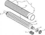
Fig. 3 three-dimensional exploded view of the present utility model.
The specific embodiment
As shown in Figure 1-Figure 3, the utility model is a kind of helical conveyer system of changing food waste separation processor, and it comprises helical feed cylinder 1, spiral conveyor rod 2, compression spring 3, lock screw 4, bearing 5, sealing baffle plate 6.
An end on described helical feed cylinder 1 is provided with charging aperture 11, and its other end is provided with the towards the opposite of discharging opening 12 and this discharging opening 12 and charging aperture 11, offers a plurality of seepage mouths 13 on the barrel of helical feed cylinder 1.
Described spiral conveyor rod 2 gaps are located in helical feed cylinder 1 and its two ends are arranged on the casing (not shown) by bearing 5 is rotatable, and spiral conveyor rod 2 is provided with flight 21; An end at spiral conveyor rod 2 is socketed sealing baffle plate 6, compression spring 3 and the lock screw 4 that is spirally connected successively on the spiral conveyor rod 2 in compression spring 3 outsides, at the outside of lock screw 4 socket bearing 5, be socketed with spiral conveyor rod 2 ends of sealing baffle plate 6 and discharging opening 12 the same sides of helical feed cylinder 1.
The effect of each parts of the utility model:
1, spiral conveyor rod 2: the conveying garbage particle prevents that granulated garbage from stopping up helical feed cylinder 1, provides the propulsive force of rubbish displacement and extruding;
2, the helical feed cylinder 1: filtering refuse moisture and fine particle;
3, compression spring 3: for sealing baffle plate 6 provides thrust, the rubbish of the moisture that prevents from not being squeezed out enters discharging opening 12;
4, sealing baffle plate 6: seal discharging opening 12 under the effect of compression spring 3 thrusts.Open when only having screw extrusion power greater than compression spring 3 thrust.
Operation principle of the present utility model:
Moisture food refuse particle after fragmentation enters helical feed cylinder 1 by charging aperture 11; To be transported to greater than the granulated garbage of seepage mouth sealing baffle plate 6 places under the effect of spiral conveyor rod 2.The extruding thrust that is subjected to spiral conveyor rod 2 when this zone granulated garbage is during greater than sealing baffle plate 6 rear portion compression spring 3 thrust; Sealing baffle plate 6 moves and opens discharging opening, and granulated garbage enters discharging opening 12 and arrives dryness storehouses under the thrust of spiral conveyor rod 2, water and less than the particle of seepage mouth discharged to the flat and superficial pond of sewage.
Emphasis of the present utility model just is: the discharging opening place at the helical feed cylinder is provided with the sealing baffle plate.
The above, it is only the utility model preferred embodiment, therefore can not limit the scope that the utility model is implemented with this, the equivalence of namely doing according to the utility model claim and description changes and modifies, and all should still belong in the scope that the utility model patent contains.
Claims (1)
1. the helical conveyer system of a changing food waste separation processor, it is characterized in that: it comprises helical feed cylinder, spiral conveyor rod, compression spring, lock screw, bearing, sealing baffle plate; An end on described helical feed cylinder is provided with charging aperture, and its other end is provided with the towards the opposite of discharging opening and this discharging opening and charging aperture, offers a plurality of seepage mouths on the barrel of helical feed cylinder; Described spiral conveyor rod gap is located in the helical feed cylinder and its two ends are arranged on casing by bearing is rotatable, and spiral conveyor rod is provided with flight; Be socketed successively the sealing baffle plate at an end of spiral conveyor rod, at an end socket compression spring of spiral conveyor rod and the lock screw that is spirally connected on the spiral conveyor rod in the compression spring outside.
Priority Applications (1)
| Application Number | Priority Date | Filing Date | Title |
|---|---|---|---|
| CN 201220566586 CN202923001U (en) | 2012-10-31 | 2012-10-31 | Screw conveying system of kitchen waste separating treater |
Applications Claiming Priority (1)
| Application Number | Priority Date | Filing Date | Title |
|---|---|---|---|
| CN 201220566586 CN202923001U (en) | 2012-10-31 | 2012-10-31 | Screw conveying system of kitchen waste separating treater |
Publications (1)
| Publication Number | Publication Date |
|---|---|
| CN202923001U true CN202923001U (en) | 2013-05-08 |
Family
ID=48212995
Family Applications (1)
| Application Number | Title | Priority Date | Filing Date |
|---|---|---|---|
| CN 201220566586 Expired - Lifetime CN202923001U (en) | 2012-10-31 | 2012-10-31 | Screw conveying system of kitchen waste separating treater |
Country Status (1)
| Country | Link |
|---|---|
| CN (1) | CN202923001U (en) |
Cited By (4)
| Publication number | Priority date | Publication date | Assignee | Title |
|---|---|---|---|---|
| CN103908817A (en) * | 2014-03-31 | 2014-07-09 | 中国农业科学院油料作物研究所 | Novel kitchen waste residue-liquid separating device |
| CN104961177A (en) * | 2015-07-28 | 2015-10-07 | 上海艾澜达泵业有限公司 | Solid-liquid separation system and solid-liquid separation device for food waste treatment |
| CN108160661A (en) * | 2017-12-11 | 2018-06-15 | 台州登尚机电有限公司 | A kind of device for processing food refuse |
| CN109955519A (en) * | 2019-05-01 | 2019-07-02 | 佛山市顺德区桥森卫厨实业有限公司 | Commercial kitchen garbage water-oil separating takes off slag and is reduced all-in-one machine |
-
2012
- 2012-10-31 CN CN 201220566586 patent/CN202923001U/en not_active Expired - Lifetime
Cited By (4)
| Publication number | Priority date | Publication date | Assignee | Title |
|---|---|---|---|---|
| CN103908817A (en) * | 2014-03-31 | 2014-07-09 | 中国农业科学院油料作物研究所 | Novel kitchen waste residue-liquid separating device |
| CN104961177A (en) * | 2015-07-28 | 2015-10-07 | 上海艾澜达泵业有限公司 | Solid-liquid separation system and solid-liquid separation device for food waste treatment |
| CN108160661A (en) * | 2017-12-11 | 2018-06-15 | 台州登尚机电有限公司 | A kind of device for processing food refuse |
| CN109955519A (en) * | 2019-05-01 | 2019-07-02 | 佛山市顺德区桥森卫厨实业有限公司 | Commercial kitchen garbage water-oil separating takes off slag and is reduced all-in-one machine |
Similar Documents
| Publication | Publication Date | Title |
|---|---|---|
| CN103085307B (en) | A kind of rubbish from cooking extracts squeezer | |
| CN202923001U (en) | Screw conveying system of kitchen waste separating treater | |
| CN102921699B (en) | Kitchen waste separating treatment system | |
| CN103121859A (en) | Kitchen waste on-site treatment method | |
| CN107159683A (en) | Refuse treatment plant | |
| CN104722557A (en) | Crushing-pulping-sorting integrated pretreatment equipment for kitchen wastes | |
| CN205042866U (en) | Organic rubbish anaerobic fermentation treatment facility | |
| CN211198996U (en) | Excrement dewatering device | |
| CN201989331U (en) | Volume reduction machine for fruit and vegetable rubbish | |
| CN101502841A (en) | Solid garbage crusher | |
| CN203862664U (en) | Device for recycling and conveying organic matters in kitchen waste | |
| CN108906180B (en) | Broken separation bundling machine of building rubbish | |
| WO2020057065A1 (en) | Internal circulation garbage separation system | |
| CN204125435U (en) | RDF production system | |
| CN202965247U (en) | Wiping presser for kitchen garbage | |
| CN201385038Y (en) | Solid waste crusher | |
| CN102873084A (en) | Oil water separation device for disposing kitchen waste | |
| CN103978719A (en) | Solid-liquid separation device for kitchen waste treatment equipment | |
| CN202921639U (en) | Kitchen waste separating treatment system | |
| CN202227413U (en) | Kitchen pond capable of solidifying and recovering abandon objects | |
| CN210974374U (en) | Municipal works sludge treatment equipment | |
| CN202683452U (en) | Spiral screening type garbage sorting machine | |
| CN212820132U (en) | High-efficient refuse treatment device | |
| CN103691729A (en) | Kitchen waste disposer | |
| CN204211048U (en) | Helical conveyer system |
Legal Events
| Date | Code | Title | Description |
|---|---|---|---|
| C14 | Grant of patent or utility model | ||
| GR01 | Patent grant | ||
| CX01 | Expiry of patent term |
Granted publication date: 20130508 |
|
| CX01 | Expiry of patent term |