CN202892125U - Denture processing machine - Google Patents
Denture processing machine Download PDFInfo
- Publication number
- CN202892125U CN202892125U CN 201220508194 CN201220508194U CN202892125U CN 202892125 U CN202892125 U CN 202892125U CN 201220508194 CN201220508194 CN 201220508194 CN 201220508194 U CN201220508194 U CN 201220508194U CN 202892125 U CN202892125 U CN 202892125U
- Authority
- CN
- China
- Prior art keywords
- axis
- feed arrangement
- axis feed
- screw mandrel
- artificial tooth
- Prior art date
- Legal status (The legal status is an assumption and is not a legal conclusion. Google has not performed a legal analysis and makes no representation as to the accuracy of the status listed.)
- Expired - Lifetime
Links
Images


Abstract
The utility model discloses a denture processing machine. The denture processing machine comprises a machine base, a cutting cooling system, a tool assembly for fixing a denture blank piece, a dual-spindle processing system with a denture processing cutter, an A-axis workpiece rotating device driving the tool assembly to rotate, a Z-axis feed device driving the dual-spindle processing system to move along the Z-axis direction, an X-axis feed device driving the Z-axis feed device to move along the X-axis direction, a Y-axis feed device driving the A-axis workpiece rotating device to move along the Y-axis direction, and a movement control system controlling the X-axis feed device, the Y-axis feed device, the Z-axis feed device and the A-axis workpiece rotating device to move; the dual-spindle processing system is arranged on the Z-axis feed device; the Z-axis feed device is arranged on the X-axis feed device; and the A-axis workpiece rotating device is arranged on the Y-axis feed device. The denture processing machine provided by the utility model can realize four-axis linkage, the processing efficiency is high, and the processing precision can be improved.
Description
Technical field
This utility model relates to a kind of artificial tooth processing machine, belongs to Oral Repair industry artificial tooth processing technique field.
Background technology
At present, the production method overwhelming majority of China's stomatology dummy is to have continued the traditional-handwork method of manufacturing technology, and this autofrettage efficient is low, and precision is not high, has increased the cycle for the treatment of, can not satisfy the requirement of the fast quick-recovery dental functions of patient.
Along with the deepening continuously and extensive use in the Oral Repair field of CAD/CAM technology, the artificial tooth reparation enters the digitized stage in recent years, and dummy fabricating quality and efficient significantly promote.The artificial tooth numerically controlled processing equipment is the key components of oral cavity CAD/CAM technology, is directly connected to the quality of artificial tooth processing characteristics.At present, domestic oral cavity CAD/CAM technology still rests on experimental stage, usually adopts the universal numerical control lathe to carry out the processing of artificial tooth digitized, and less for the research of oral artificial tooth reparation special purpose machine tool, and achievement in research is very few especially.
There is following some problem in existing artificial tooth process equipment: 1, adopt general three axis numerically controlled machine to carry out artificial tooth processing, only have X-axis, Y-axis and Z axis, lathe is bulky, can't satisfy the demand of oral cavity doctor's in-house operation.2, the artificial tooth long processing time of three axis numerically controlled machine, patient's waiting time is of a specified duration.3, universal machine tools complicated operation, non-pro personnel can't operate lathe, have limited artificial tooth and have repaired digitized process.Existing pair of spindle false tooth machining tool complicated in mechanical structure, the system development difficulty is large, and machining accuracy is not high.
The many defectives that exist for solving above-mentioned artificial tooth prosthetic appliance, task of the present utility model is to manufacture and design a kind of artificial tooth process equipment, and it has two axis systems, the processing of two spindle synchronous, working (machining) efficiency is high; Each modular construction of lathe is compact to design, and volume is small and exquisite, suitable stomatological hospital clinical manipulation; The Machinery Tool Automation degree is high, and is easy and simple to handle.
Summary of the invention
Technical problem to be solved in the utility model is the defective that overcomes prior art, provide a kind of can realize four-axle linked, the artificial tooth processing machine that working (machining) efficiency is high, can improve machining accuracy.
In order to solve the problems of the technologies described above, the technical solution of the utility model is: a kind of artificial tooth processing machine, and it comprises: support; The cooling for cut system; The tool component of fixed denture embryo spare; Two spindle processing system with artificial tooth process tool; Drive the A shaft-like work rotary apparatus of tool component rotation; Drive the Z axis feed arrangement that two spindle processing systems move as Z-axis direction; Drive the X-axis feed arrangement that the Z axis feed arrangement moves as X axis; Drive the Y-axis feed arrangement that A shaft-like work rotary apparatus moves as Y-axis; The kinetic control system of control X-axis feed arrangement, Y-axis feed arrangement, Z axis feed arrangement and the action of A shaft-like work rotary apparatus; Two spindle processing system is installed on the Z axis feed arrangement, and the Z axis feed arrangement is installed on the X-axis feed arrangement, and A shaft-like work rotary apparatus is installed on the Y-axis feed arrangement, and cooling for cut system and kinetic control system are installed in the support.
Further, described A shaft-like work rotary apparatus comprises A axle electric rotating machine, decelerator and rotation installation component, A axle electric rotating machine is connected with decelerator, and described tool component is installed on the output shaft of reductor, and described A axle electric rotating machine and decelerator are installed on the rotation installation component.
Further, two spindle processing system comprises two spindle motors, motor cabinet, connecting plate and Z-direction supporting plate, described artificial tooth process tool is installed on the motor shaft of spindle motor, two spindle motors are installed on the motor cabinet, motor cabinet is connected with the Z-direction supporting plate by connecting plate, and the Z-direction supporting plate is connected with the Z axis feed arrangement.
Further, described Y-axis feed arrangement comprises Y-direction screw mandrel, Y-direction feed screw nut, the Y-direction guide rail slide block is secondary and drive the Y-direction feeding motor that the Y-direction screw mandrel rotates, the Y-direction screw mandrel can be rotated to support on the described support, Y-direction feed screw nut is threaded connection on the Y-direction screw mandrel, described A shaft-like work rotary apparatus is fixedly connected with the Y-direction feed screw nut, and A shaft-like work rotary apparatus is slidably mounted on the support by Y-direction guide rail slide block pair.
Further, described Z axis feed arrangement comprises Z-direction screw mandrel, Z-direction feed screw nut, Z-direction guide rail slide block pair, X-direction supporting plate and drives the Z-direction feeding motor of Z-direction screw mandrel rotation, the Z-direction screw mandrel can be rotated to support on the X-direction supporting plate, Z-direction feed screw nut is threaded connection on the Z-direction screw mandrel, described pair of spindle processing system is fixedly connected with the Z-direction feed screw nut, and two spindle processing system is slidably mounted on the X-direction supporting plate by Z-direction guide rail slide block pair.
Further, described X-axis feed arrangement comprises X-direction screw mandrel, X-direction feed screw nut, X-direction guide rail slide block pair, X-direction installation component, middle holder connecting plate and drives the X-direction feeding motor of X-direction screw mandrel rotation, the X-direction screw mandrel can be rotated to support on the X-direction installation component, X-direction feed screw nut is threaded connection on the X-direction screw mandrel, the X-direction installation component is fixed on the support, described Z axis feed arrangement is fixedly connected with middle holder connecting plate, middle holder connecting plate is fixedly connected with the X-direction feed screw nut, and middle holder connecting plate is slidably mounted on the X-direction installation component by X-direction guide rail slide block pair.
Further, be fixedly connected with to realize being connected of Z axis feed arrangement and middle holder connecting plate by the X-direction supporting plate in the Z axis feed arrangement and middle holder connecting plate.
After having adopted technique scheme, the utlity model has following beneficial effect:
1, working (machining) efficiency is high.Of the present utility model pair of spindle processing system can carry out roughing and polish to artificial tooth embryo spare, and working (machining) efficiency is processed obviously more by hand to be increased, and the artificial tooth embryo spare on the tool component that need to not change the outfit again in roughing and accurately machined operation.
2, this utility model has been realized four-axle linked, rotation by kinetic control system control X-direction feeding motor, Y-direction feeding motor, Z-direction feeding motor and A axle electric rotating machine, realize the corresponding X axis of artificial tooth processing machine, Y-axis, Z-axis direction and the axial motion of A, A axially namely A shaft-like work rotary apparatus realized the positive and negative processing of artificial tooth embryo spare.
3, this utility model can improve the machining accuracy to artificial tooth, because this artificial tooth processing machine is realized four-axle linked by kinetic control system control, and in rapid processing, with the cooling for cut system working position is cooled off, realized full-automatic processing, and this utility model links to each other with digital control scanning equipment, utilize its model to process, than adopting Digit Control Machine Tool processing, higher to the machining accuracy of artificial tooth.
4, the feed arrangement of X-axis of the present utility model, Y-axis and Z axis adopts the secondary transferring power of nut screw, and transmission efficiency is high, and transmission accuracy is high, and staring torque is little, and creeping can not appear during low speed in movement sensitive, has further improved machining accuracy of the present utility model.
Description of drawings
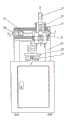
Fig. 1 is the axonometric chart of artificial tooth processing machine of the present utility model;
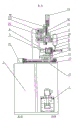
Fig. 2 is the structural representation of artificial tooth processing machine of the present utility model;
Fig. 3 is the B-B cutaway view of Fig. 2;
Fig. 4 is the A-A cutaway view of Fig. 2.
The specific embodiment
Content of the present utility model is easier to be expressly understood in order to make, and the below is described in further detail this utility model according to specific embodiment also by reference to the accompanying drawings,
Shown in Fig. 1 ~ 4, a kind of artificial tooth processing machine, it comprises: support 1; Cooling for cut system 2; The tool component 3 of fixed denture embryo spare; Two spindle processing system with artificial tooth process tool 4; Drive the A shaft-like work rotary apparatus of tool component 3 rotations; Drive the Z axis feed arrangement that two spindle processing systems move as Z-axis direction; Drive the X-axis feed arrangement that the Z axis feed arrangement moves as X axis; Drive the Y-axis feed arrangement that A shaft-like work rotary apparatus moves as Y-axis; The kinetic control system 5 of control X-axis feed arrangement, Y-axis feed arrangement, Z axis feed arrangement and the action of A shaft-like work rotary apparatus; Two spindle processing system is installed on the Z axis feed arrangement, and the Z axis feed arrangement is installed on the X-axis feed arrangement, and A shaft-like work rotary apparatus is installed on the Y-axis feed arrangement, and cooling for cut system 2 and kinetic control system 5 are installed in the support 1.Like this, this artificial tooth processing machine working (machining) efficiency is just very high.Two spindle processing system can carry out roughing and polish to artificial tooth embryo spare, and working (machining) efficiency is processed obviously more by hand to be increased, and the artificial tooth embryo spare on the tool component that need to not change the outfit again in roughing and accurately machined operation.This utility model has been realized four-axle linked, action by kinetic control system 5 control X-direction feed arrangements, Y-direction feed arrangement, Z-direction feed arrangement and A shaft-like work rotary apparatus, realize the corresponding X axis of artificial tooth processing machine, Y-axis, Z-axis direction and the axial motion of A, A axially namely A shaft-like work rotary apparatus realized the positive and negative processing of artificial tooth embryo spare.This utility model can improve the machining accuracy to artificial tooth, because this artificial tooth processing machine is realized four-axle linked by kinetic control system 5 controls, and in rapid processing, cool off with 2 pairs of working positions of cooling for cut system, realized full-automatic processing, and this utility model links to each other with digital control scanning equipment, utilize its model to process, than adopting Digit Control Machine Tool processing, higher to the machining accuracy of artificial tooth.
A shaft-like work rotary apparatus can be realized by following structure the tool component rotation, thereby realize the positive and negative processing to artificial tooth embryo spare, as shown in Figure 3, A shaft-like work rotary apparatus comprises A axle electric rotating machine 6, decelerator 7 and rotation installation component 28, A axle electric rotating machine 6 is connected with decelerator 7, tool component 3 is installed on the output shaft of reductor 7, and A axle electric rotating machine 6 and decelerator 7 are installed on the rotation installation component 28.
Two spindle processing system is for the ease of being connected with the Z axis feed arrangement, simultaneously can carry out roughing and polish to artificial tooth embryo spare, as shown in Figure 3, two spindle processing system comprises two spindle motors 8, motor cabinet 9, connecting plate 10 and Z-direction supporting plate 11, artificial tooth process tool 4 is installed on the motor shaft of spindle motor 8, two spindle motors 8 are installed on the motor cabinet 9, and motor cabinet 9 is connected with Z-direction supporting plate 11 by connecting plate 10, and Z-direction supporting plate 11 is connected with the Z axis feed arrangement.
The Y-axis feed arrangement can be realized by following syndeton the feed motion on the artificial tooth processing machine Y direction, as shown in Figure 3, the Y-axis feed arrangement comprises Y-direction screw mandrel 12, Y-direction feed screw nut 13, the Y-direction feeding motor 15 of Y-direction guide rail slide block secondary 14 and 12 rotations of driving Y-direction screw mandrel, Y-direction screw mandrel 12 can be rotated to support on the support 1 by supporting base 27, Y-direction feed screw nut 13 is threaded connection on Y-direction screw mandrel 12, described A shaft-like work rotary apparatus is fixedly connected with Y-direction feed screw nut 13, and A shaft-like work rotary apparatus is slidably mounted on the support 1 by Y-direction guide rail slide block pair 14.
The Z axis feed arrangement can be realized by following syndeton the feed motion on the artificial tooth processing machine Z-direction, as shown in Figure 3, the Z axis feed arrangement comprises Z-direction screw mandrel 16, Z-direction feed screw nut 17, Z-direction guide rail slide block pair 18, the Z-direction feeding motor 20 of X-direction supporting plate 19 and 16 rotations of driving Z-direction screw mandrel, Z-direction screw mandrel 16 can be rotated to support on the X-direction supporting plate 19, Z-direction feed screw nut 17 is threaded connection on Z-direction screw mandrel 16, two spindle processing system is fixedly connected with Z-direction feed screw nut 17, and two spindle processing system is slidably mounted on the X-direction supporting plate 19 by Z-direction guide rail slide block pair 18.
The X-axis feed arrangement can be realized by following syndeton the feed motion on the artificial tooth processing machine X-direction,
As shown in Figure 4, the X-axis feed arrangement comprises X-direction screw mandrel 21, X-direction feed screw nut 22, X-direction guide rail slide block pair 23, X-direction installation component 24, the X-direction feeding motor 26 of middle holder connecting plate 25 and 21 rotations of driving X-direction screw mandrel, X-direction screw mandrel 21 can be rotated to support on the X-direction installation component 24, X-direction feed screw nut 22 is threaded connection on X-direction screw mandrel 21, X-direction installation component 24 is fixed on the support 1, the Z axis feed arrangement is fixedly connected with middle holder connecting plate 25, middle holder connecting plate 25 is fixedly connected with X-direction feed screw nut 22, and middle holder connecting plate 25 is slidably mounted on the X-direction installation component 24 by X-direction guide rail slide block pair 23.Can be fixedly connected with to realize being connected of Z axis feed arrangement and middle holder connecting plate 25 by the X-direction supporting plate 19 in the Z axis feed arrangement and middle holder connecting plate 25.
Operation principle of the present utility model is as follows:
At first utilize digital control scanning equipment to carry out 3-D scanning to tooth model, then the tooth mould figure after utilizing CAD scanning special-purpose software to scanning is edited, again tooth mould file is input to and carries out machining path calculating in the CAM artificial tooth special-purpose software, obtain Machining Path, after finishing the work of CAD/CAM, the NC path is sent to carries out three-dimensional processing on the artificial tooth processing machine, artificial tooth embryo spare is fixed on the tool component 3, first being processed starts cooling for cut system 2 in advance, guarantee that main shaft can run well by persistent high efficiency, then opening movement control system 5 is controlled X-direction feeding motors 26, Y-direction feeding motor 15 and Z-direction feeding motor 20 and A axle electric rotating machine 6 utilize the 4 pairs of artificial tooth embryo spares of artificial tooth process tool on main shaft of two spindle processing systems to carry out roughing, carry out polish with the 4 pairs of artificial tooth embryo spares of artificial tooth process tool on No. two main shafts of two spindle processing systems again, whole artificial tooth manufacturing procedure has just been finished.
Above-described specific embodiment; the purpose of this utility model, technical scheme and beneficial effect are further described; institute is understood that; the above only is specific embodiment of the utility model; be not limited to this utility model; all within spirit of the present utility model and principle, any modification of making, be equal to replacement, improvement etc., all should be included within the protection domain of the present utility model.
Claims (7)
1. an artificial tooth processing machine is characterized in that, it comprises:
Support (1);
Cooling for cut system (2);
The tool component of fixed denture embryo spare (3);
Two spindle processing system with artificial tooth process tool (4);
Drive the A shaft-like work rotary apparatus of tool component (3) rotation;
Drive the Z axis feed arrangement that two spindle processing systems move as Z-axis direction;
Drive the X-axis feed arrangement that the Z axis feed arrangement moves as X axis;
Drive the Y-axis feed arrangement that A shaft-like work rotary apparatus moves as Y-axis;
The kinetic control system (5) of control X-axis feed arrangement, Y-axis feed arrangement, Z axis feed arrangement and the action of A shaft-like work rotary apparatus;
Two spindle processing system is installed on the Z axis feed arrangement, and the Z axis feed arrangement is installed on the X-axis feed arrangement, and A shaft-like work rotary apparatus is installed on the Y-axis feed arrangement, and cooling for cut system (2) and kinetic control system (5) are installed in the support (1).
2. artificial tooth processing machine according to claim 1, it is characterized in that: described A shaft-like work rotary apparatus comprises A axle electric rotating machine (6), decelerator (7) and rotation installation component (28), A axle electric rotating machine (6) is connected with decelerator (7), described tool component (3) is installed on the output shaft of reductor (7), and described A axle electric rotating machine (6) and decelerator (7) are installed on the rotation installation component (28).
3. artificial tooth processing machine according to claim 1, it is characterized in that: described pair of spindle processing system comprises two spindle motors (8), motor cabinet (9), connecting plate (10) and Z-direction supporting plate (11), described artificial tooth process tool (4) is installed on the motor shaft of spindle motor (8), two spindle motors (8) are installed on the motor cabinet (9), motor cabinet (9) is connected with Z-direction supporting plate (11) by connecting plate (10), and Z-direction supporting plate (11) is connected with the Z axis feed arrangement.
4. artificial tooth processing machine according to claim 1 and 2, it is characterized in that: described Y-axis feed arrangement comprises Y-direction screw mandrel (12), Y-direction feed screw nut (13), the Y-direction feeding motor (15) of Y-direction guide rail slide block secondary (14) and driving Y-direction screw mandrel (12) rotation, Y-direction screw mandrel (12) can be rotated to support on the described support (1), Y-direction feed screw nut (13) is threaded connection on Y-direction screw mandrel (12), described A shaft-like work rotary apparatus is fixedly connected with Y-direction feed screw nut (13), and A shaft-like work rotary apparatus is slidably mounted on the support (1) by Y-direction guide rail slide block secondary (14).
5. according to claim 1 or 3 described artificial tooth processing machines, it is characterized in that: described Z axis feed arrangement comprises Z-direction screw mandrel (16), Z-direction feed screw nut (17), Z-direction guide rail slide block secondary (18), the Z-direction feeding motor (20) of X-direction supporting plate (19) and driving Z-direction screw mandrel (16) rotation, Z-direction screw mandrel (16) can be rotated to support on the X-direction supporting plate (19), Z-direction feed screw nut (17) is threaded connection on Z-direction screw mandrel (16), described pair of spindle processing system is fixedly connected with Z-direction feed screw nut (17), and two spindle processing system is slidably mounted on the X-direction supporting plate (19) by Z-direction guide rail slide block secondary (18).
6. artificial tooth processing machine according to claim 1, it is characterized in that: described X-axis feed arrangement comprises X-direction screw mandrel (21), X-direction feed screw nut (22), X-direction guide rail slide block secondary (23), X-direction installation component (24), the X-direction feeding motor (26) of middle holder connecting plate (25) and driving X-direction screw mandrel (21) rotation, X-direction screw mandrel (21) can be rotated to support on the X-direction installation component (24), X-direction feed screw nut (22) is threaded connection on X-direction screw mandrel (21), X-direction installation component (24) is fixed on the support (1), described Z axis feed arrangement is fixedly connected with middle holder connecting plate (25), middle holder connecting plate (25) is fixedly connected with X-direction feed screw nut (22), and middle holder connecting plate (25) is slidably mounted on the X-direction installation component (24) by X-direction guide rail slide block secondary (23).
7. artificial tooth processing machine according to claim 5, it is characterized in that: described X-axis feed arrangement comprises X-direction screw mandrel (21), X-direction feed screw nut (22), X-direction guide rail slide block secondary (23), X-direction installation component (24), the X-direction feeding motor (26) of middle holder connecting plate (25) and driving X-direction screw mandrel (21) rotation, X-direction screw mandrel (21) can be rotated to support on the X-direction installation component (24), X-direction feed screw nut (22) is threaded connection on X-direction screw mandrel (21), X-direction installation component (24) is fixed on the support (1), the X-direction supporting plate (19) of described Z axis feed arrangement is fixedly connected with middle holder connecting plate (25), middle holder connecting plate (25) is fixedly connected with X-direction feed screw nut (22), and middle holder connecting plate (25) is slidably mounted on the X-direction installation component (24) by X-direction guide rail slide block secondary (23).
Priority Applications (1)
| Application Number | Priority Date | Filing Date | Title |
|---|---|---|---|
| CN 201220508194 CN202892125U (en) | 2012-09-29 | 2012-09-29 | Denture processing machine |
Applications Claiming Priority (1)
| Application Number | Priority Date | Filing Date | Title |
|---|---|---|---|
| CN 201220508194 CN202892125U (en) | 2012-09-29 | 2012-09-29 | Denture processing machine |
Publications (1)
| Publication Number | Publication Date |
|---|---|
| CN202892125U true CN202892125U (en) | 2013-04-24 |
Family
ID=48112852
Family Applications (1)
| Application Number | Title | Priority Date | Filing Date |
|---|---|---|---|
| CN 201220508194 Expired - Lifetime CN202892125U (en) | 2012-09-29 | 2012-09-29 | Denture processing machine |
Country Status (1)
| Country | Link |
|---|---|
| CN (1) | CN202892125U (en) |
Cited By (2)
| Publication number | Priority date | Publication date | Assignee | Title |
|---|---|---|---|---|
| CN102871751A (en) * | 2012-09-29 | 2013-01-16 | 常州特舒隆机电设备有限公司 | Artificial tooth machining machine |
| CN107584536A (en) * | 2017-09-29 | 2018-01-16 | 江阴市人民医院 | Pressing film maintainer cutter |
-
2012
- 2012-09-29 CN CN 201220508194 patent/CN202892125U/en not_active Expired - Lifetime
Cited By (3)
| Publication number | Priority date | Publication date | Assignee | Title |
|---|---|---|---|---|
| CN102871751A (en) * | 2012-09-29 | 2013-01-16 | 常州特舒隆机电设备有限公司 | Artificial tooth machining machine |
| CN102871751B (en) * | 2012-09-29 | 2015-07-15 | 常州特舒隆机电设备有限公司 | Artificial tooth machining machine |
| CN107584536A (en) * | 2017-09-29 | 2018-01-16 | 江阴市人民医院 | Pressing film maintainer cutter |
Similar Documents
| Publication | Publication Date | Title |
|---|---|---|
| CN102871751B (en) | Artificial tooth machining machine | |
| CN201399678Y (en) | Numerically controlled milling and grinding machining tool | |
| CN201012467Y (en) | Turbine blade numerical-controlled abrasive belt grinding machine | |
| CN201195245Y (en) | Five-shaft five-linkage machining center | |
| CN103084854B (en) | A kind of numerical control machine tool and rotary table thereof | |
| CN101870063A (en) | Vertical five axle interlocked gantry digital control milling machining center | |
| CN101502890A (en) | Double-main shaft double-speed compound numerical control milling machine | |
| CN106624189A (en) | Numerical control grinder for forming machining | |
| CN201329498Y (en) | Double spindle mechanism in machining center | |
| CN104190954A (en) | Synchronous double-spindle-box numerically controlled lathe | |
| CN110181104A (en) | A kind of numerical control milling machine tool convenient for adjusting tilt angle | |
| CN202892125U (en) | Denture processing machine | |
| CN102248228B (en) | Numerical-control hobbing device for face gear | |
| CN111482502A (en) | Rotary radial feeding numerical control spinning machine | |
| CN201702463U (en) | Straight bevel gear machine tool | |
| CN206605246U (en) | A kind of Working table structure of vertical turn-milling complex machining center | |
| CN201338215Y (en) | Reconfigurable production system combined with drilling, turning and milling functions | |
| CN204686446U (en) | Numerical-control turn-milling walks crosshead shoe the 3rd Zhou Zu mechanism that scheming coordinates with positive axis mechanism | |
| CN101733415A (en) | Six-spindle bar numerical control lathe | |
| CN207858454U (en) | A kind of numerical control multi-spindle gantry machining center | |
| CN203092127U (en) | Lathing and grinding combined machining machine tool | |
| CN213052814U (en) | Numerical control three-hole drilling machine | |
| CN201618869U (en) | Full automatic numerical control three-shaft driller | |
| CN211102910U (en) | Permanent magnet motor driven vertical lathe | |
| CN209206477U (en) | A kind of double carriage structures of binary channels numerically controlled lathe |
Legal Events
| Date | Code | Title | Description |
|---|---|---|---|
| C14 | Grant of patent or utility model | ||
| GR01 | Patent grant | ||
| CX01 | Expiry of patent term |
Granted publication date: 20130424 |
|
| CX01 | Expiry of patent term |