CN202804346U - Vertical sawing machine - Google Patents
Vertical sawing machine Download PDFInfo
- Publication number
- CN202804346U CN202804346U CN 201220477641 CN201220477641U CN202804346U CN 202804346 U CN202804346 U CN 202804346U CN 201220477641 CN201220477641 CN 201220477641 CN 201220477641 U CN201220477641 U CN 201220477641U CN 202804346 U CN202804346 U CN 202804346U
- Authority
- CN
- China
- Prior art keywords
- saw
- base
- frame assembly
- band
- bearing
- Prior art date
- Legal status (The legal status is an assumption and is not a legal conclusion. Google has not performed a legal analysis and makes no representation as to the accuracy of the status listed.)
- Expired - Fee Related
Links
Images

Landscapes
- Sawing (AREA)
Abstract
The utility model relates to a vertical sawing machine, belonging to the technical field of sawing equipment. The utility model aims at providing a vertical sawing machine which can cut large-size workpieces and is short in processing time. According to the technical scheme adopted, the vertical sawing machine comprises a base, a saw frame assembly and a feeding device, wherein the feeding device is arranged in the middle of the base, the saw frame assembly is arranged above the feeding device through two guide pillars fixedly arranged on the base, the cylinder bodies of two hydraulic cylinders are fixedly arranged on the base, and the ends of piston rods of the two hydraulic cylinders are connected with the saw frame assembly. According to the vertical sawing machine, a saw belt is fixed in a horizontal direction through a horizontal guiding device, the saw belt can be controlled by the hydraulic cylinders to move up and down to the processing position along with the saw frame assembly, a workpiece is clamped by the feeding device below the saw belt to move towards the direction of the saw belt for processing, the use is more convenient, the manual cost can be saved, and the processing range is wide.
Description
Technical field
A kind of vertical saw of the utility model belongs to the sawing equipment technical field.
Background technology
The machining accuracy of sawing machine is generally all not bery high, drives the saw blade running by driving wheel and driven pulley, and saw blade fracture direction is by the control of guide rail control frame.Bands for band is aligned straightening cut device through overscan sawing is swept by adjusting the rotation bearing.By dropping into sawed-off material under the hydraulic cylinder piston rod supporting guide control frame, be equipped with on the band sawing machine manually or hydraulic jack material folding retaining mechanism, and the hydraulic operation threshold switch etc.Old-fashioned vertical saw saw band is advanced to saw direction and is controlled by guide rail, and saw band cutting stroke is limited, and the maximum 350mm of hydraulic tongs clamping size.Generally only be used for radially cutting off bar, materials in the tube, hydraulic tongs design size and band saw stroke have limited to this kind sawing machine can only process small size workpiece, and purposes is single, the range of work is limited, long processing time.
The utility model content
The utility model overcomes the deficiency that prior art exists, and technical problem to be solved provides a kind ofly can cut short vertical saw of large-size workpiece, process time.
In order to solve the problems of the technologies described above, the technical scheme that the utility model adopts is: a kind of vertical saw, comprise base, saw frame assembly and feed arrangement, the centre of base is equipped with feed arrangement, the saw frame assembly is installed in the top of feed arrangement by being fixed on two guide pillars on the base, the cylinder body of two hydraulic cylinders is fixed on the base, and the piston rod end of two hydraulic cylinders is connected with the saw frame assembly;
The structure of feed arrangement is: bearing is fixedly mounted on the base, the screw rod two ends of leading screw are installed in the below of bearing by bearing, the top of bearing is movably installed with fixed mount, the fixed mount bottom is fixedly connected with the nut of screw mandrel, is installed with the first motor of the bolt rotary of control leading screw on the bearing;
The structure of saw frame assembly is: casing tilts to be installed on the lead and the casing middle part has downward groove, the both sides that two leading trucks and two leading trucks lay respectively at feed arrangement are installed in the groove, the horizontally-guided device all is installed on each leading truck, the inside of casing is equipped with two band saw wheels, two band saw wheels pass two horizontally-guided devices on the leading truck by saw band connection and saw band, and the second motor that the control band saw wheel rotates is installed on the casing.
Described horizontally-guided device is that two directive wheel horizontal parallel are installed.
The utility model is compared the beneficial effect that has with prior art: the horizontally-guided device in the utility model is fixed as horizontal direction with saw band, saw band can move up and down Working position by hydraulic cylinder control with the saw frame assembly, the feed arrangement holding workpiece of saw band below moves processed to the saw band direction, use convenient, saved cost of labor, the range of work is wide.
Description of drawings
The utility model is described in further detail below in conjunction with accompanying drawing.
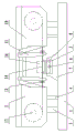
Fig. 1 is structural representation of the present utility model.
Fig. 2 is the structural representation of feed arrangement in the utility model.
Among the figure: 1 is base, and 2 is the saw frame assembly, and 3 is feed arrangement, and 4 is hydraulic cylinder, and 5 is lead, and 6 is leading screw, 7 is bearing, and 8 is fixed mount, and 9 is the first motor, and 10 is casing, and 11 is leading truck, 12 is the horizontally-guided device, and 13 is directive wheel, and 14 is saw band, and 15 is the second motor, and 16 is workpiece.
The specific embodiment
As shown in Figure 1 and Figure 2, a kind of vertical saw of the utility model, comprise base 1, saw frame assembly 2 and feed arrangement 3, the centre of base 1 is equipped with feed arrangement 3, saw frame assembly 2 is installed in the top of feed arrangement 3 by being fixed on two guide pillars 5 on the base 1, the cylinder body of two hydraulic cylinders 4 is fixed on the base 1, and the piston rod end of two hydraulic cylinders 4 is connected with saw frame assembly 2;
The structure of feed arrangement 3 is: bearing 7 is fixedly mounted on the base 1, the screw rod two ends of leading screw 6 are installed in the below of bearing 7 by bearing, the top of bearing 7 is movably installed with fixed mount 8, fixed mount 8 bottoms are fixedly connected with the nut of screw mandrel 6, are installed with the first motor 9 of the bolt rotary of control leading screw 6 on the bearing 6;
The structure of saw frame assembly 2 is: casing 10 tilts to be installed on the lead 5 and casing 10 middle parts have downward groove, the both sides that two leading trucks 11 and two leading trucks 11 lay respectively at feed arrangement 3 are installed in the groove, on each leading truck 11 horizontally-guided device 12 is installed all, the inside of casing 10 is equipped with two band saw wheels 13, two band saw wheels 13 pass two horizontally-guided devices 12 on the leading truck 11 by saw band 14 connections and saw band 14, and the second motor 15 that control band saw wheel 13 rotates is installed on the casing 10.
Described horizontally-guided device 12 is that two directive wheel horizontal parallel are installed.
The gap of leaving between two directive wheels 13 is passed saw band 14 and saw band 14 is set to horizontal direction.
The course of work
On fixed mount 8, the piston rod of hydraulic cylinder 4 stretches out or the adjustment saw frame assembly 2 of retracting makes two saw bands 14 between the horizontally-guided device 12 move to required working height with workpiece 16 fixed clamp;
Open the second motor 15, make band saw wheel 13 drive saw band 14 and make cutting movement;
Open the first motor 9, the workpiece 16 that makes leading screw 6 drive clamping on the fixed mount 8 moves and is cut by saw band 14 to saw band 14;
Another part workpiece of replaceable processing after workpiece 16 cutting at one time are finished is perhaps adjusted saw band 14 by hydraulic cylinder 4 and is highly continued workpiece 16 is carried out the cutting second time.
Claims (2)
1. vertical saw, it is characterized in that: comprise base (1), saw frame assembly (2) and feed arrangement (3), the centre of base (1) is equipped with feed arrangement (3), saw frame assembly (2) is installed in the top of feed arrangement (3) by being fixed on two guide pillars (5) on the base (1), the cylinder body of two hydraulic cylinders (4) is fixed on the base (1), and the piston rod end of two hydraulic cylinders (4) is connected with saw frame assembly (2);
The structure of feed arrangement (3) is: bearing (7) is fixedly mounted on the base (1), the screw rod two ends of leading screw (6) are installed in the below of bearing (7) by bearing, the top of bearing (7) is movably installed with fixed mount (8), fixed mount (8) bottom is fixedly connected with the nut of screw mandrel (6), is installed with first motor (9) of the bolt rotary of control leading screw (6) on the bearing (6);
The structure of saw frame assembly (2) is: casing (10) tilts to be installed in lead (5) upward and casing (10) middle part has downward groove, the both sides that two leading trucks (11) and two leading trucks (11) lay respectively at feed arrangement (3) are installed in the groove, horizontally-guided device (12) all is installed on each leading truck (11), the inside of casing (10) is equipped with two band saw wheels (13), two band saw wheels (13) connect by saw band (14) and saw band (14) is passed horizontally-guided device (12) on two leading trucks (11), and the second motor (15) that control band saw wheel (13) rotates is installed on the casing (10).
2. a kind of vertical saw according to claim 1 is characterized in that: described horizontally-guided device (12) is that two directive wheel horizontal parallel are installed.
Priority Applications (1)
| Application Number | Priority Date | Filing Date | Title |
|---|---|---|---|
| CN 201220477641 CN202804346U (en) | 2012-09-19 | 2012-09-19 | Vertical sawing machine |
Applications Claiming Priority (1)
| Application Number | Priority Date | Filing Date | Title |
|---|---|---|---|
| CN 201220477641 CN202804346U (en) | 2012-09-19 | 2012-09-19 | Vertical sawing machine |
Publications (1)
| Publication Number | Publication Date |
|---|---|
| CN202804346U true CN202804346U (en) | 2013-03-20 |
Family
ID=47863290
Family Applications (1)
| Application Number | Title | Priority Date | Filing Date |
|---|---|---|---|
| CN 201220477641 Expired - Fee Related CN202804346U (en) | 2012-09-19 | 2012-09-19 | Vertical sawing machine |
Country Status (1)
| Country | Link |
|---|---|
| CN (1) | CN202804346U (en) |
Cited By (4)
| Publication number | Priority date | Publication date | Assignee | Title |
|---|---|---|---|---|
| CN103240463A (en) * | 2013-06-03 | 2013-08-14 | 江苏科技大学 | Special sawing machine for large members |
| CN103447615A (en) * | 2013-08-28 | 2013-12-18 | 襄阳远锐资源工程技术有限公司 | Band sawing machine for cutting waste lead-acid storage batteries |
| CN107225289A (en) * | 2017-07-20 | 2017-10-03 | 苏州晓炎自动化设备有限公司 | A kind of vehicle dormer window guide rail cutter device |
| CN109226887A (en) * | 2018-11-14 | 2019-01-18 | 泉州苗亿自动化机械有限公司 | A kind of revolving horizontal sawing machine |
-
2012
- 2012-09-19 CN CN 201220477641 patent/CN202804346U/en not_active Expired - Fee Related
Cited By (7)
| Publication number | Priority date | Publication date | Assignee | Title |
|---|---|---|---|---|
| CN103240463A (en) * | 2013-06-03 | 2013-08-14 | 江苏科技大学 | Special sawing machine for large members |
| CN103240463B (en) * | 2013-06-03 | 2015-05-27 | 江苏科技大学 | Special sawing machine for large members |
| CN103447615A (en) * | 2013-08-28 | 2013-12-18 | 襄阳远锐资源工程技术有限公司 | Band sawing machine for cutting waste lead-acid storage batteries |
| CN103447615B (en) * | 2013-08-28 | 2015-09-30 | 襄阳远锐资源工程技术有限公司 | A kind of band sawing machine cutting waste and old lead acid accumulator |
| CN107225289A (en) * | 2017-07-20 | 2017-10-03 | 苏州晓炎自动化设备有限公司 | A kind of vehicle dormer window guide rail cutter device |
| CN109226887A (en) * | 2018-11-14 | 2019-01-18 | 泉州苗亿自动化机械有限公司 | A kind of revolving horizontal sawing machine |
| CN109226887B (en) * | 2018-11-14 | 2023-09-29 | 泉州苗亿自动化机械有限公司 | Rotary horizontal sawing machine |
Similar Documents
| Publication | Publication Date | Title |
|---|---|---|
| CN205167255U (en) | Stone cutter | |
| CN201592274U (en) | Adjustable bidirectional plane milling device | |
| CN201483582U (en) | Circular sawing machine with quarter-sawn lumber material | |
| CN211192344U (en) | Online cutting device is used in steel pipe production | |
| CN212636090U (en) | Cutting mechanism for processing aerated concrete building blocks | |
| CN101575797B (en) | Semi-automatic double-pole umbrella fabric pressure cutting machine | |
| CN113306029B (en) | Squarer | |
| CN202804346U (en) | Vertical sawing machine | |
| CN209223255U (en) | Safe type plate shearing machine | |
| CN201632916U (en) | Abrasive wheel cutting machine | |
| CN203110160U (en) | Bridge type stone cutting machine with polishing function | |
| CN103240463A (en) | Special sawing machine for large members | |
| CN201128176Y (en) | Woodworking cross four-edge cutting machine | |
| CN204413376U (en) | A kind of crosspointer pad welding machine | |
| CN103394751A (en) | Double-head cutting machine | |
| CN203344134U (en) | Material pressing mechanism of multi-shaft intelligent numerical control mortising machine | |
| CN216706150U (en) | Automatic feeding type circular sawing machine | |
| CN105397498A (en) | Indoor flower stand processing and production line | |
| CN202137456U (en) | Sawing machine | |
| CN201677365U (en) | Reciprocating type automatic milling machine | |
| CN201208662Y (en) | Pneumatic milling machine | |
| CN202951932U (en) | Band sawing machine | |
| CN201217150Y (en) | Numerical control drill-saw composite machine tool for section steel | |
| CN202367269U (en) | Prestressed sawing machine for railways, highways and bridges | |
| CN202367811U (en) | Boosting mechanism of back-feeding high speed computer cut-to-size saw |
Legal Events
| Date | Code | Title | Description |
|---|---|---|---|
| C14 | Grant of patent or utility model | ||
| GR01 | Patent grant | ||
| C17 | Cessation of patent right | ||
| CF01 | Termination of patent right due to non-payment of annual fee |
Granted publication date: 20130320 Termination date: 20130919 |