CN202792923U - Spiral heat exchange device for rotary kiln - Google Patents
Spiral heat exchange device for rotary kiln Download PDFInfo
- Publication number
- CN202792923U CN202792923U CN201220372330XU CN201220372330U CN202792923U CN 202792923 U CN202792923 U CN 202792923U CN 201220372330X U CN201220372330X U CN 201220372330XU CN 201220372330 U CN201220372330 U CN 201220372330U CN 202792923 U CN202792923 U CN 202792923U
- Authority
- CN
- China
- Prior art keywords
- pipe
- spiral heat
- heat exchange
- flange plate
- rotary kiln
- Prior art date
- Legal status (The legal status is an assumption and is not a legal conclusion. Google has not performed a legal analysis and makes no representation as to the accuracy of the status listed.)
- Expired - Fee Related
Links
Images



Classifications
-
- Y—GENERAL TAGGING OF NEW TECHNOLOGICAL DEVELOPMENTS; GENERAL TAGGING OF CROSS-SECTIONAL TECHNOLOGIES SPANNING OVER SEVERAL SECTIONS OF THE IPC; TECHNICAL SUBJECTS COVERED BY FORMER USPC CROSS-REFERENCE ART COLLECTIONS [XRACs] AND DIGESTS
- Y02—TECHNOLOGIES OR APPLICATIONS FOR MITIGATION OR ADAPTATION AGAINST CLIMATE CHANGE
- Y02P—CLIMATE CHANGE MITIGATION TECHNOLOGIES IN THE PRODUCTION OR PROCESSING OF GOODS
- Y02P10/00—Technologies related to metal processing
- Y02P10/25—Process efficiency
Landscapes
- Muffle Furnaces And Rotary Kilns (AREA)
- Heat-Exchange Devices With Radiators And Conduit Assemblies (AREA)
Abstract
The utility model discloses a spiral heat exchange device for a rotary kiln. The spiral heat exchange device for the rotary kiln comprises a spiral heat exchange pipe, a water inlet collecting box, a water outlet collecting box and a pipe set fixing member. The pipe set fixing member comprises a convex flange plate and a concave flange plate, wherein the convex flange plate and the concave flange plate are matched, the convex flange plate is provided with installation holes, a cavity is arranged on one side of the concave flange plate, a pipe connecting hole is arranged on the other side of the concave flange plate, a boss and the cavity are connected in matched mode and sealed through a sealing gasket, the water inlet end and the water outlet end of the spiral heat exchange pipe are respectively and fixedly connected with the installation holes of the convex flange plate, the pipe connecting hole of the concave flange plate is respectively connected with the water inlet collecting box or the water outlet collecting box through a pipe connecting pipe, and a water supply circulation pump is used for pressurizing to perform forced circulation so as to recover waste heat through the heat exchange pipe. The spiral heat exchange device for the rotary kiln overcomes the defect that waste heat of an original rotary kiln cannot be used reasonably and has the advantages of being simple in structure, convenient to dismantle and replace, easy to install, low in manufacturing cost, reliable in sealing performance, high in heat exchange efficiency and long in service life.
Description
Technical field
The utility model relates to the boiler technology field, relates in particular to a kind of spiral heat exchanger that can be applicable to various rotary kilns.
Background technology
In industrial production a lot of industrial products that need calcining are arranged, often adopt rotary kiln to calcine, because calcining can produce a large amount of heats, many heats that rotary kiln surface can distribute, these heats pass through the direct transfer spreading of rotary kiln wall in air, not only seriously influence our existence and working environment, simultaneously to the waste of resource reutilization.
The fuel that is often used for the industry calcining mostly is non-renewable resources, if can integrate recycling to resource under the prerequisite that does not affect normal production, both can drop into by saving resource, reduces production costs, and can reduce again the pollution to environment.Along with the enhancing of people's economy consciousness, environmental consciousness, UTILIZATION OF VESIDUAL HEAT IN had obtained good change in recent years, such as cement kiln waste-heat oven, glass kiln residual heat stove, metallurgical waste heat stove etc., was well developed and used.But because the aspects such as technology, structure restriction, the UTILIZATION OF VESIDUAL HEAT IN technology of rotary kiln also is in blank substantially, and most heats that calcining produces in the rotary kiln waste, therefore, demand designing a kind of device that can fully absorb, transform the rotary kiln waste heat urgently, improve the rotary kiln UTILIZATION OF VESIDUAL HEAT IN.
The utility model content
In order to overcome above-mentioned existing technological deficiency, the purpose of this utility model be to provide a kind of simple in structure, applied widely, be easy to dismounting, be used for the spiral heat exchanger of rotary kiln.
In order to achieve the above object, the utility model is achieved through the following technical solutions: the utility model is a kind of spiral heat exchanger for rotary kiln, comprises spiral heat exchange tube, water inlet header, water outlet header 3 and pipe group fixture.Pipe group fixture comprises suitable boss flange plate and recessed flanged plate, boss flange plate one side has been attacked boss, opposite side has installing hole, have cylindrical void corresponding with installing hole and that be communicated with on the described boss, recessed flanged plate one side has cavity, and its opposite side has pipe corresponding with cavity and that be communicated with and connects the hole, wherein boss is connected with cavity is adaptive, and cylindrical void is filled with sealing gasket, and it is relative one by one that installing hole and pipe connect the hole, and each organizes corresponding installing hole and pipe connects between the hole by the mutual isolating seal of sealing gasket.The spiral heat exchange tube that carries out heat exchange as recirculated water into and out of water end (W.E.) respectively with place rotary kiln before and after the installing hole of boss flange plate of both sides be fixedly connected with, and respectively with rotary kiln before and after the boss flange plate suitable be connected the pipe of recessed flanged plate connect the hole and take over respectively by pipe and be communicated with water inlet header and water outlet header.Many group spiral heat exchange tubes are spirally wrapped around on the rotary kiln, and by fixing with the adaptive boss flange plate that is connected and recessed flanged plate, and by recessed flanged plate bottom the pipe adapter that connects and the header of intaking, water outlet header composition water circulation heat-exchanger rig, by the forced circulation of pressurizeing to water-circulating pump, make recirculated water enter spiral heat exchange tube from the header of intaking, carry out heat exchange with rotary kiln when in pipe, flowing, being applied through the collection of water outlet header and processing again.
As optimization, the number of the installing hole on the described flange flange is greater than the number of cylindrical void, do further to optimize, cylindrical void corresponding and be communicated with respectively to organize the installing hole pitch-row identical, so that the spiral heat exchange tube 1 that will be connected with boss flange plate 5 divides according to the pipe group of some, to improve the scope of application.
As optimization, described boss flange plate and recessed flanged plate edge part have all been attacked connecting hole, and corresponding one by one, by add securing member in the boss flange plate connecting hole relative with recessed flanged plate, with flanged plate be connected the adaptive connection multiple spot of flanged plate and fix, improve stabilized structure.
As optimization, described spiral heat exchange tube is fixedly connected with the installing hole of boss flange plate into and out of the mode of water end (W.E.) by welding, technique is simple, and can satisfy intensity and seal request that pipe connects, do further to optimize, described spiral heat exchange tube is the insulation material parcel again, to reduce heat loss.
As optimization, the mode that described pipe is taken over by welding connects the hole with pipe respectively, and water inlet header or the connection of water outlet header, and technique is simple, and can satisfy intensity and seal request that pipe connects.
Compared with prior art, the beneficial effects of the utility model are: this apparatus structure is comparatively simple, be convenient in batches split production, dismounting is comparatively easy, and device is fixedly connected with spiral heat exchange tube by special concave, convex flanged plate structure, make the structure of device more firm, have simultaneously cheap for manufacturing costly, sealing property is reliable, the advantage that long service life and heat exchange efficiency are high, thereby realize to reclaim preferably the purpose of various rotary kiln waste heats, be conducive to promote the energy-saving and emission-reduction of producing.
Description of drawings
The utility model will illustrate by example and with reference to the mode of accompanying drawing, wherein:
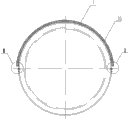
Fig. 1 is the utility model scheme of installation;
Fig. 2 is I section enlarged diagram among Fig. 1;
Fig. 3 is II section enlarged diagram among Fig. 1;
Fig. 4 is boss flange plate cutaway view;
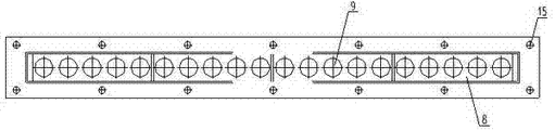
Fig. 5 is boss flange plate top view;
Fig. 6 is boss flange plate sectional view;
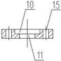
Fig. 7 is recessed flanged plate cutaway view;
Fig. 8 is recessed flanged plate top view;
Fig. 9 is recessed flanged plate sectional view;
Figure 10 is recessed flanged plate connection diagram;
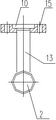
Figure 11 is that recessed flanged plate side connects cutaway view;
Figure 12 is the utility model scheme of installation.
Mark among the figure: spiral heat exchange tube 1, water inlet header 2, water outlet header 3, pipe group fixture 4, boss flange plate 5, recessed flanged plate 6, boss 7, cylindrical void 8, installing hole 9, cavity 10, pipe connect hole 11, pipe adapter 13, connecting hole 14, refractory layer 15.
The specific embodiment
Below in conjunction with accompanying drawing, the utility model is described in detail.
In order to make the purpose of this utility model, technical scheme and advantage clearer, below in conjunction with drawings and Examples, the utility model is further elaborated.Should be appreciated that specific embodiment described herein only in order to explaining the utility model, and be not used in restriction the utility model.
Such as Fig. 1, shown in Fig. 2 and Fig. 3, the utility model the utility model is a kind of spiral heat exchanger for rotary kiln, comprise spiral heat exchange tube 1, water inlet header 2, water outlet header 3 and pipe group fixture 4, the pipe group fixture 4 that its connection and exchange heat pipe are fixed is as shown in Fig. 4 to 9, comprise boss flange plate 5 and recessed flanged plate 6, boss flange plate 5 one sides have been attacked boss 7, opposite side has installing hole 9, have cylindrical void 8 and installing hole 9 corresponding and connections on the boss 7, the number of installing hole 9 is greater than the number of cylindrical void 8, cylindrical void 8 corresponding and be communicated with respectively to organize installing hole 9 pitch-rows identical, be convenient to divide into groups according to quantity exchange heat pipe.Recessed flanged plate 6 one sides have cavity 10, its opposite side has with cavity 10 pipes corresponding and that be communicated with and connects hole 11, and by boss 7 and 10 adaptive connections of cavity, organize annular seal space corresponding to installing hole at each cylindrical void 8 as each, its inside is filled with sealing gasket, when boss flange plate 5 when being connected flanged plate 6 adaptive connection, it is relative one by one that installing hole 9 and pipe connect hole 11, each is organized corresponding installing hole and pipe and connects between the hole by the mutual isolating seal of sealing gasket, i.e. the separate runner of respectively organizing that connects that the hole forms with each group installing hole, pipe respectively of through hole on the sealing gasket.As shown in Fig. 1, Fig. 2, Fig. 3, Figure 10 and Figure 11, the spiral heat exchange tube 1 that carries out heat exchange as recirculated water is welded and fixed with the installing hole 9 of the boss flange plate 5 that places forward and backward position, rotary kiln both sides respectively into and out of water end (W.E.), with boss flange plate 5 suitable be connected the pipe of recessed flanged plate 6 connect hole 11 and take over 13 by pipe and is communicated with water inlet header 2 and water outlet header 3 respectively, wherein pipe 13 modes by welding of taking over connect hole 11 with pipe respectively and the perforate of intake header 2 or water outlet header 3 is connected.
Such as Fig. 1, Fig. 2, shown in Fig. 3 and Figure 12, many group spiral heat exchange tubes 1 are spirally wrapped around on the rotary kiln, it advances, delivery port is weldingly fixed on respectively in the installing hole 9 of boss flange plate 5, and the pipe of recessed flanged plate 6 connects hole 11 and the welding of pipe adapter 13 1 ends, the other end of pipe adapter 13 then welds with the perforate of water inlet header 2 or water outlet header 3, be welded on pipe that the spiral heat exchange tubes 1 in the installing hole 9 of flanged plate 5 connect by recessed flanged plate 6 bottoms take over 13 with the header 2 of intaking, water outlet header 3 forms the water circulation heat-exchanger rig, by the forced circulation of pressurizeing to water-circulating pump, make recirculated water enter spiral heat exchange tube 1 from the header 2 of intaking, carry out heat exchange with rotary kiln when in pipe, flowing, being applied through 3 collections of water outlet header and processing again.After finishing, assembling need integral body to carry out the water pressure test, the guarantee sealing is good, and the water-circulating pump that adopts is the adjustable speed circulating pump, can reach control outlet of water heater medium temperature by regulating pump flow when making its concrete use, reaches the purpose of reasonable distribution rotary kiln surface temperature.
Spiral heat exchange tube 1 in a spiral manner spiral at rotary kiln surface, the flow process distance of long medium, guaranteed heat-exchange time, arrange between heat exchanger tube closely, with the whole parcel of rotary kiln, improved space availability ratio, guaranteed the abundant absorption of heat, and lay insulation material on the set of heat exchange tubes surface, can reduce greatly radiation loss, greatly improved heat exchange efficiency.Many group spiral heat exchange tubes consist of set of heat exchange tubes, and segmentation group in the pipe group, namely take group as unit, carry out cycle heat exchange with spiral form around the rotary kiln wall, according to different caloric receptivities and water yield demand, only need to regulate the quantity of pipe in each group, and the number of configuration helix tube group gets final product.Take the heat-exchanger rig shown in figure XX as example, comprise 20 spiral pipe in the single spiral heat exchange tube group, each Guan Zuzhong is divided into again 5 groups of groups arranged side by side, and each group comprises 4 helix tubes.
It is recessed that spiral heat exchange tube 1 and pipe are taken over 13 employings, boss flange plate male and fomale(M﹠F) is connected, upper lower flange is that male and fomale(M﹠F) cooperates, the centre is added with sealing gasket, each spiral heat exchange tube 1 is arranged in the sealing of official family fixture 4 in the assurance whole system, set of heat exchange tubes and pipe adapter group are by recessed, installing hole 9 on the boss flange plate and pipe connect hole 11 and will manage component and be made into independently group, medium in each group is for circulating alone, boss flange plate 5 and recessed flanged plate 6 edge parts have all been attacked connecting hole 14, and corresponding one by one, by in the relative connecting hole 14 of boss flange plate 5 and recessed flanged plate 6, adding securing member, being connected of flanged plate 5 and recessed flanged plate 6 carried out Multi-point fastening, improve stabilized structure, securing member can adopt by bolt, the routine that spring washer and nut form tightens up accessory, for the convenient rotary kiln that cooperates uses, can weld bracing frame 2 times at recessed flanged plate, further improve the stability that device uses.
The above only is preferred embodiment of the present utility model; not in order to limit the utility model; all any modifications of within spirit of the present utility model and principle, doing, be equal to and replace and improvement etc., all should be included within the protection domain of the present utility model.
Claims (7)
1. spiral heat exchanger that is used for rotary kiln, comprise spiral heat exchange tube (1), water inlet header (2), water outlet header (3) and pipe group fixture (4), it is characterized in that: described pipe group fixture (4) comprises suitable boss flange plate (5) and recessed flanged plate (6), boss flange plate (5) one sides have been attacked boss (7), opposite side has installing hole (9), have cylindrical void (8) corresponding with installing hole (9) and that be communicated with on the described boss (7), recessed flanged plate (6) one sides have cavity (10), its opposite side has pipe corresponding with cavity (10) and that be communicated with and connects hole (11), wherein boss (7) and suitable connection of cavity (10), be filled with sealing gasket at cylindrical void (8), it is relative one by one that installing hole (9) and pipe connect hole (11); Described spiral heat exchange tube (1) is fixedly connected with the installing hole (9) of boss flange plate (5) respectively into and out of water end (W.E.), and the pipe of recessed flanged plate (6) connects hole (11) and is communicated with water inlet header (2) or water outlet header (3) by pipe adapter (13).
2. a kind of spiral heat exchanger for rotary kiln according to claim 1, it is characterized in that: the number of the installing hole (9) on the described flange flange (5) is greater than the number of cylindrical void (8).
3. a kind of spiral heat exchanger for rotary kiln according to claim 2 is characterized in that: described cylindrical void (8) installing hole (9) pitch-row corresponding and that be communicated with is identical.
4. a kind of spiral heat exchanger for rotary kiln according to claim 1, it is characterized in that: described boss flange plate (5) and recessed flanged plate (6) edge part have all been attacked connecting hole (14), and corresponding one by one.
5. a kind of spiral heat exchanger for rotary kiln according to claim 1 is characterized in that: described spiral heat exchange tube (1) is fixedly connected with the installing hole (9) of boss flange plate (5) into and out of the mode of water end (W.E.) by welding.
6. a kind of spiral heat exchanger for rotary kiln according to claim 4 is characterized in that: described spiral heat exchange tube (1) is outside to be wrapped up by heat-insulation layer (15).
7. a kind of spiral heat exchanger for rotary kiln according to claim 1 is characterized in that: described pipe is taken over (13) mode by welding and is connect hole (11) with pipe respectively, and water inlet header (2) or water outlet header (3) are communicated with.
Priority Applications (1)
| Application Number | Priority Date | Filing Date | Title |
|---|---|---|---|
| CN201220372330XU CN202792923U (en) | 2012-07-30 | 2012-07-30 | Spiral heat exchange device for rotary kiln |
Applications Claiming Priority (1)
| Application Number | Priority Date | Filing Date | Title |
|---|---|---|---|
| CN201220372330XU CN202792923U (en) | 2012-07-30 | 2012-07-30 | Spiral heat exchange device for rotary kiln |
Publications (1)
| Publication Number | Publication Date |
|---|---|
| CN202792923U true CN202792923U (en) | 2013-03-13 |
Family
ID=47820175
Family Applications (1)
| Application Number | Title | Priority Date | Filing Date |
|---|---|---|---|
| CN201220372330XU Expired - Fee Related CN202792923U (en) | 2012-07-30 | 2012-07-30 | Spiral heat exchange device for rotary kiln |
Country Status (1)
| Country | Link |
|---|---|
| CN (1) | CN202792923U (en) |
Cited By (3)
| Publication number | Priority date | Publication date | Assignee | Title |
|---|---|---|---|---|
| CN103335514A (en) * | 2013-06-05 | 2013-10-02 | 石家庄新华能源环保科技股份有限公司 | Rotary kiln device provided with energy recovery equipment |
| CN106017148A (en) * | 2016-07-08 | 2016-10-12 | 东海县凯凯石英制品有限公司 | Large-diameter quartz tube heat exchange equipment |
| CN109012124A (en) * | 2018-09-26 | 2018-12-18 | 苏州西热节能环保技术有限公司 | A kind of dangerous waste incineration flue gas depth denitration purification system and method |
-
2012
- 2012-07-30 CN CN201220372330XU patent/CN202792923U/en not_active Expired - Fee Related
Cited By (4)
| Publication number | Priority date | Publication date | Assignee | Title |
|---|---|---|---|---|
| CN103335514A (en) * | 2013-06-05 | 2013-10-02 | 石家庄新华能源环保科技股份有限公司 | Rotary kiln device provided with energy recovery equipment |
| CN106017148A (en) * | 2016-07-08 | 2016-10-12 | 东海县凯凯石英制品有限公司 | Large-diameter quartz tube heat exchange equipment |
| CN106017148B (en) * | 2016-07-08 | 2018-08-21 | 东海县凯凯石英制品有限公司 | A kind of heavy caliber quartz ampoule heat transmission equipment |
| CN109012124A (en) * | 2018-09-26 | 2018-12-18 | 苏州西热节能环保技术有限公司 | A kind of dangerous waste incineration flue gas depth denitration purification system and method |
Similar Documents
| Publication | Publication Date | Title |
|---|---|---|
| CN109654930B (en) | Vertical layered phase change heat storage device based on special-shaped fins | |
| CN106591887B (en) | A kind of aluminium cell side wall device for generating power by waste heat based on organic flash distillation cycle | |
| CN202792923U (en) | Spiral heat exchange device for rotary kiln | |
| CN203671912U (en) | Water tank for air source heat pump water heater | |
| CN105066083A (en) | U-shaped-row-tube type fused salt steam generating device and method | |
| CN110145947A (en) | A kind of high temperature and pressure compressed air heat exchanger structure | |
| CN206468589U (en) | A kind of centrifugal air compressor heat reclamation device | |
| CN208567130U (en) | A kind of heating device integrating solar energy, air energy and electric energy | |
| CN211863902U (en) | Energy-saving rectifying tower for chemical industry | |
| CN202432887U (en) | Novel flue gas waste heat recovery device | |
| CN201011473Y (en) | Double U shaped pressure bearing heat collector | |
| CN209840229U (en) | Heating operation system of energy saver of gas/oil steam boiler | |
| CN103234271A (en) | Dual system Freon path dividing heat pump water heater | |
| CN202902673U (en) | Horizontal hot water tank of solar water heater | |
| CN106870077A (en) | A kind of gas turbine of energy-conserving and environment-protective | |
| CN207701210U (en) | A kind of jet dynamic control tail gas waste heat utilizing device | |
| CN202002070U (en) | Component type heat pipe steam generator for furnace | |
| CN220959762U (en) | Waste heat utilization device of refrigerating unit | |
| CN205448359U (en) | Horizontal intubate solar water heater of integral type with bank of tubes formula water tank | |
| CN220119611U (en) | Microchannel condenser for circulating air source heat pump water heater | |
| CN204630113U (en) | A kind of full-plastic pressure-bearing dual cycle solar water container | |
| CN203586171U (en) | Low temperature difference organic working medium evaporator utilizing low temperature heat energy | |
| CN203669945U (en) | Waste heat recovery device for indirect air cooling unit | |
| CN209877338U (en) | High-efficiency single-liner double-circulation module | |
| CN104061695B (en) | One is superthermal leads the two inner bag solar engineering double-row heat collector of U-tube |
Legal Events
| Date | Code | Title | Description |
|---|---|---|---|
| C14 | Grant of patent or utility model | ||
| GR01 | Patent grant | ||
| CF01 | Termination of patent right due to non-payment of annual fee |
Granted publication date: 20130313 Termination date: 20180730 |
|
| CF01 | Termination of patent right due to non-payment of annual fee |