CN202770112U - Device for low-load production of air separation plant - Google Patents
Device for low-load production of air separation plant Download PDFInfo
- Publication number
- CN202770112U CN202770112U CN2012202945295U CN201220294529U CN202770112U CN 202770112 U CN202770112 U CN 202770112U CN 2012202945295 U CN2012202945295 U CN 2012202945295U CN 201220294529 U CN201220294529 U CN 201220294529U CN 202770112 U CN202770112 U CN 202770112U
- Authority
- CN
- China
- Prior art keywords
- air compressor
- small air
- outlet valve
- air separation
- separation plant
- Prior art date
- Legal status (The legal status is an assumption and is not a legal conclusion. Google has not performed a legal analysis and makes no representation as to the accuracy of the status listed.)
- Expired - Lifetime
Links
Images
Classifications
-
- F—MECHANICAL ENGINEERING; LIGHTING; HEATING; WEAPONS; BLASTING
- F25—REFRIGERATION OR COOLING; COMBINED HEATING AND REFRIGERATION SYSTEMS; HEAT PUMP SYSTEMS; MANUFACTURE OR STORAGE OF ICE; LIQUEFACTION SOLIDIFICATION OF GASES
- F25J—LIQUEFACTION, SOLIDIFICATION OR SEPARATION OF GASES OR GASEOUS OR LIQUEFIED GASEOUS MIXTURES BY PRESSURE AND COLD TREATMENT OR BY BRINGING THEM INTO THE SUPERCRITICAL STATE
- F25J3/00—Processes or apparatus for separating the constituents of gaseous or liquefied gaseous mixtures involving the use of liquefaction or solidification
- F25J3/02—Processes or apparatus for separating the constituents of gaseous or liquefied gaseous mixtures involving the use of liquefaction or solidification by rectification, i.e. by continuous interchange of heat and material between a vapour stream and a liquid stream
- F25J3/04—Processes or apparatus for separating the constituents of gaseous or liquefied gaseous mixtures involving the use of liquefaction or solidification by rectification, i.e. by continuous interchange of heat and material between a vapour stream and a liquid stream for air
- F25J3/04763—Start-up or control of the process; Details of the apparatus used
- F25J3/04769—Operation, control and regulation of the process; Instrumentation within the process
- F25J3/04812—Different modes, i.e. "runs" of operation
-
- F—MECHANICAL ENGINEERING; LIGHTING; HEATING; WEAPONS; BLASTING
- F25—REFRIGERATION OR COOLING; COMBINED HEATING AND REFRIGERATION SYSTEMS; HEAT PUMP SYSTEMS; MANUFACTURE OR STORAGE OF ICE; LIQUEFACTION SOLIDIFICATION OF GASES
- F25J—LIQUEFACTION, SOLIDIFICATION OR SEPARATION OF GASES OR GASEOUS OR LIQUEFIED GASEOUS MIXTURES BY PRESSURE AND COLD TREATMENT OR BY BRINGING THEM INTO THE SUPERCRITICAL STATE
- F25J3/00—Processes or apparatus for separating the constituents of gaseous or liquefied gaseous mixtures involving the use of liquefaction or solidification
- F25J3/02—Processes or apparatus for separating the constituents of gaseous or liquefied gaseous mixtures involving the use of liquefaction or solidification by rectification, i.e. by continuous interchange of heat and material between a vapour stream and a liquid stream
- F25J3/04—Processes or apparatus for separating the constituents of gaseous or liquefied gaseous mixtures involving the use of liquefaction or solidification by rectification, i.e. by continuous interchange of heat and material between a vapour stream and a liquid stream for air
- F25J3/04763—Start-up or control of the process; Details of the apparatus used
- F25J3/04866—Construction and layout of air fractionation equipments, e.g. valves, machines
- F25J3/04951—Arrangements of multiple air fractionation units or multiple equipments fulfilling the same process step, e.g. multiple trains in a network
- F25J3/04957—Arrangements of multiple air fractionation units or multiple equipments fulfilling the same process step, e.g. multiple trains in a network and inter-connecting equipments upstream of the fractionation unit (s), i.e. at the "front-end"
-
- F—MECHANICAL ENGINEERING; LIGHTING; HEATING; WEAPONS; BLASTING
- F25—REFRIGERATION OR COOLING; COMBINED HEATING AND REFRIGERATION SYSTEMS; HEAT PUMP SYSTEMS; MANUFACTURE OR STORAGE OF ICE; LIQUEFACTION SOLIDIFICATION OF GASES
- F25J—LIQUEFACTION, SOLIDIFICATION OR SEPARATION OF GASES OR GASEOUS OR LIQUEFIED GASEOUS MIXTURES BY PRESSURE AND COLD TREATMENT OR BY BRINGING THEM INTO THE SUPERCRITICAL STATE
- F25J2230/00—Processes or apparatus involving steps for increasing the pressure of gaseous process streams
- F25J2230/24—Multiple compressors or compressor stages in parallel
-
- F—MECHANICAL ENGINEERING; LIGHTING; HEATING; WEAPONS; BLASTING
- F25—REFRIGERATION OR COOLING; COMBINED HEATING AND REFRIGERATION SYSTEMS; HEAT PUMP SYSTEMS; MANUFACTURE OR STORAGE OF ICE; LIQUEFACTION SOLIDIFICATION OF GASES
- F25J—LIQUEFACTION, SOLIDIFICATION OR SEPARATION OF GASES OR GASEOUS OR LIQUEFIED GASEOUS MIXTURES BY PRESSURE AND COLD TREATMENT OR BY BRINGING THEM INTO THE SUPERCRITICAL STATE
- F25J2230/00—Processes or apparatus involving steps for increasing the pressure of gaseous process streams
- F25J2230/40—Processes or apparatus involving steps for increasing the pressure of gaseous process streams the fluid being air
-
- F—MECHANICAL ENGINEERING; LIGHTING; HEATING; WEAPONS; BLASTING
- F25—REFRIGERATION OR COOLING; COMBINED HEATING AND REFRIGERATION SYSTEMS; HEAT PUMP SYSTEMS; MANUFACTURE OR STORAGE OF ICE; LIQUEFACTION SOLIDIFICATION OF GASES
- F25J—LIQUEFACTION, SOLIDIFICATION OR SEPARATION OF GASES OR GASEOUS OR LIQUEFIED GASEOUS MIXTURES BY PRESSURE AND COLD TREATMENT OR BY BRINGING THEM INTO THE SUPERCRITICAL STATE
- F25J2290/00—Other details not covered by groups F25J2200/00 - F25J2280/00
- F25J2290/60—Details about pipelines, i.e. network, for feed or product distribution
Landscapes
- Engineering & Computer Science (AREA)
- Physics & Mathematics (AREA)
- Mechanical Engineering (AREA)
- Thermal Sciences (AREA)
- General Engineering & Computer Science (AREA)
- Separation By Low-Temperature Treatments (AREA)
Abstract
A device for low-load operation of an air separation plant belongs to the technical field of cryogenic oxygen producing equipment and is used for low-load production of the air separation plant. The technical scheme adopted is that the device comprises more than two small air compressors and supporting valves, each small air compressor is provided with a check valve and an outlet valve in sequential connection; all the outlet valves are connected through pipelines with outlet valves respectively mounted therein; the outlet valve of one small air compressor is connected with another outlet valve and the air separation plant through the pipeline; and a pipe connection bleeding valve is arranged on the connecting pipeline of each small air compressor and the corresponding check valve. According to the utility model, the plurality of small air compressors are used for production, rather than the large air compressor body; the small air compressors can be reversed for air separation low-load production without air separation parking and restart; and the equipment load as design is minimized to 75 percent, and the electrical quantity is saved by 50 percent. Therefore, the device provided by the utility model has the advantages of simple structure, convenience in operation, safety, practicability, and remarkably lowered manufacturing cost.
Description
Technical field
The utility model relates to a kind of device that can make the air separation plant load operation, especially uses the servicing unit on cryogenic air separation oxygen processed, belongs to deep cooling oxygen generating plant technical field.
Background technology
Adopting at present the cryogenic refrigeration method to produce oxygen is the technological means that generally adopts, and along with the variation in production market, the air separation unit underload production of sometimes having to is tackled huge cost pressure.In real work, find, in again must not unproductive situation when reducing in a large number with gas, because air compressor machine power consumption is proportional with compression tolerance, take pipeline connect the small air compressor outlet conduit replace the air compressor machine of equipment own for the production of, can when sky divides underload to produce, reduce the unit cost of production.Therefore, might design a kind of new device that is used for the production of air separation plant underload, to reduce cost, realize producing under the low load condition.
The utility model content
Technical problem to be solved in the utility model provides a kind ofly can use a plurality of small air compressors to replace supporting air compressor machine to carry out the device that the air separation plant underload is produced that is used for that underload produces.
The technical scheme that solves the problems of the technologies described above is:
A kind of device for the production of air separation plant underload, it is comprised of a plurality of small air compressors more than two and supporting outlet valve, check-valves, diffusion valve, every small air compressor and a check-valves, an outlet valve are linked in sequence, these several outlet valves are connected by pipeline again, in connecting pipe, there is respectively outlet valve to cut off, wherein the outlet valve that connects of small air compressor is connected with air separation plant with another outlet valve by pipeline, has respectively pipeline to be connected diffusion valve on the connecting line of every small air compressor and check-valves.
Above-mentioned device for the production of air separation plant underload, setting pressure flowmeter behind the outlet valve of described each small air compressor, flow is counted elbow meter.
The beneficial effects of the utility model are:
The utility model two or many small air compressors can be replaced equipment itself greatly air compressor machines produce, need not stop in empty minute to restart and just can switch small air compressor and carry out sky and divide underload production, can reduce machine utilization minimum to 75% according to design, save electric weight and reach 50%.The utility model not only makes empty minute underload production function, and can divide continuous and stable production under the prerequisite of not stopping at sky, and it is simple in structure, and is easy to operate, safe and practical, and production cost reduces obviously.
Description of drawings
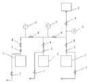
Fig. 1 is structural representation of the present utility model.
Mark is as follows among the figure: 1# air compressor machine 1,2# air compressor machine 2,3# air compressor machine 3, outlet valve 4, check-valves 5, diffusion valve 6, flowmeter 7, air separation plant 8.
The specific embodiment
The utility model is by being comprised of a plurality of small air compressors more than two and supporting outlet valve 4, check-valves 5, diffusion valve 6, flowmeter 7.
Show among the figure, an embodiment of the present utility model adopts three small air compressors, is respectively 1# air compressor machine 1,2# air compressor machine 2,3# air compressor machine 3.Each small air compressor and a check-valves 5, an outlet valve 4 are linked in sequence, these three outlet valves 4 are connected by pipeline again, in connecting pipe, there are respectively two outlet valves 4 to cut off, three small air compressors are divided into independently loop, 2# air compressor machine 2,3# air compressor machine 3 completely cut off with 1 segmentation of 1# air compressor machine, can realize independent supply.
Show among the figure, the outlet valve 4 that connects at 1# air compressor machine 1 is connected with air separation plant 8 with another outlet valve 4 by pipeline, and air separation plant 8 can be connected with three small air compressors respectively by outlet valve 4, is used alone or in combination.
Show on the connecting line of every small air compressor and check-valves 5, have respectively pipeline to be connected diffusion valve 6, the outlet valve 4 rear setting pressure flowmeters 7 of every small air compressor among the figure.
Pipeline of the present utility model is withstand voltage stainless steel pipes, pressure-bearing 1.0Mpa, and outlet valve 4 is Hand-operated butterfly valve, flowmeter 7 is selected elbow meter.
The utility model not only has to the underload production function, and can carry not stopping and reduce load production, and it is simple in structure, and easy to operate, production is stablized.Except being used for empty minute underload production, also can being used for other large enterprise's source of the gas and replacing.
The course of work of the present utility model is as follows:
The utility model is used between the oxygen generating station air compressor machine, reducing gradually original equipment sends into air capacity and can be undertaken by air compressor machine diffusion valve 6, also can be undertaken by 1 outlet valve 4 of 1# air compressor machine in this device, open gradually the outlet valve 4 of 2# air compressor machine 2,3# air compressor machine 3 simultaneously.Pay close attention to changes in flow rate in the opening process, pressure changes, and accomplishes that pressure point is stable, and flow reaches re-set target.
Claims (2)
1. one kind is used for the device that the air separation plant underload is produced, it is characterized in that: it is by a plurality of small air compressors more than two and supporting outlet valve (4), check-valves (5), diffusion valve (6) forms, every small air compressor and a check-valves (5), an outlet valve (4) is linked in sequence, these several outlet valves (4) are connected by pipeline again, in connecting pipe, there is respectively outlet valve (4) to cut off, wherein the outlet valve (4) that connects of small air compressor is connected with air separation plant (8) with another outlet valve (4) by pipeline, has respectively pipeline to be connected diffusion valve (6) on the connecting line of every small air compressor and check-valves (5).
2. the device of producing for the air separation plant underload according to claim 1, it is characterized in that: setting pressure flowmeter (7) behind the outlet valve of described each small air compressor (4), flowmeter (7) is elbow meter.
Priority Applications (1)
| Application Number | Priority Date | Filing Date | Title |
|---|---|---|---|
| CN2012202945295U CN202770112U (en) | 2012-06-21 | 2012-06-21 | Device for low-load production of air separation plant |
Applications Claiming Priority (1)
| Application Number | Priority Date | Filing Date | Title |
|---|---|---|---|
| CN2012202945295U CN202770112U (en) | 2012-06-21 | 2012-06-21 | Device for low-load production of air separation plant |
Publications (1)
| Publication Number | Publication Date |
|---|---|
| CN202770112U true CN202770112U (en) | 2013-03-06 |
Family
ID=47776678
Family Applications (1)
| Application Number | Title | Priority Date | Filing Date |
|---|---|---|---|
| CN2012202945295U Expired - Lifetime CN202770112U (en) | 2012-06-21 | 2012-06-21 | Device for low-load production of air separation plant |
Country Status (1)
| Country | Link |
|---|---|
| CN (1) | CN202770112U (en) |
Cited By (4)
| Publication number | Priority date | Publication date | Assignee | Title |
|---|---|---|---|---|
| CN103245167A (en) * | 2013-05-24 | 2013-08-14 | 济钢集团有限公司 | Running device and running method for loads of multiple machine sets of oxygenator to jointly vary |
| CN105318193A (en) * | 2014-07-31 | 2016-02-10 | 宝山钢铁股份有限公司 | Low-pressure nitrogen gas header pipe system and control method |
| CN111561440A (en) * | 2020-03-27 | 2020-08-21 | 彩虹(合肥)液晶玻璃有限公司 | High efficiency air compressor machine unit control system |
| CN113669627A (en) * | 2021-08-16 | 2021-11-19 | 南京钢铁股份有限公司 | Pipe network system and method for increasing oxygen yield by utilizing surplus compressed air |
-
2012
- 2012-06-21 CN CN2012202945295U patent/CN202770112U/en not_active Expired - Lifetime
Cited By (6)
| Publication number | Priority date | Publication date | Assignee | Title |
|---|---|---|---|---|
| CN103245167A (en) * | 2013-05-24 | 2013-08-14 | 济钢集团有限公司 | Running device and running method for loads of multiple machine sets of oxygenator to jointly vary |
| CN103245167B (en) * | 2013-05-24 | 2015-12-09 | 济钢集团有限公司 | A kind of oxygenerator multicomputer associating variable load operation device and method |
| CN105318193A (en) * | 2014-07-31 | 2016-02-10 | 宝山钢铁股份有限公司 | Low-pressure nitrogen gas header pipe system and control method |
| CN105318193B (en) * | 2014-07-31 | 2018-01-30 | 宝山钢铁股份有限公司 | A kind of low-pressure nitrogen manifold system and control method |
| CN111561440A (en) * | 2020-03-27 | 2020-08-21 | 彩虹(合肥)液晶玻璃有限公司 | High efficiency air compressor machine unit control system |
| CN113669627A (en) * | 2021-08-16 | 2021-11-19 | 南京钢铁股份有限公司 | Pipe network system and method for increasing oxygen yield by utilizing surplus compressed air |
Similar Documents
| Publication | Publication Date | Title |
|---|---|---|
| CN202770112U (en) | Device for low-load production of air separation plant | |
| CN201757268U (en) | CNG station quick gas filling device | |
| CN203892106U (en) | Power generating system making use of recycled water feeding pressure | |
| CN203809247U (en) | Oil supply system on compressor set pulled by steam turbine | |
| CN204962299U (en) | User's gas pressure regulating cabinet system | |
| CN201155420Y (en) | Hydroturbine emergency stop device based on cartridge valve | |
| CN208811041U (en) | A kind of moulding machine penetrates sand making-up air device | |
| CN203442476U (en) | Air-supply circulating system of air engine | |
| CN103042053B (en) | A kind of water system parallel for ultrafast cold-peace section cooling dual system | |
| CN202012324U (en) | Module structure of gas injection and gas extraction for gas storage wellhead | |
| CN202595794U (en) | Well group closed pressure-superposed water supply system | |
| CN103062626A (en) | Intelligent dispatching device for local pneumatic pipe networks | |
| CN202387755U (en) | Large hydraulic pump station with step-less adjustable pressure and flow | |
| CN203572109U (en) | Chilled water system of parallel volume expansion refrigeration machines | |
| CN202596690U (en) | Pressure boost water injection device | |
| CN202360417U (en) | Water supply device of improved water-ring vacuum pump | |
| CN203374483U (en) | Frequency conversion type screw compressor flow device | |
| CN202826642U (en) | Vacuum device used for laminating machine | |
| CN204063786U (en) | A kind of syndeton that can make air separation unit underrun | |
| CN201715245U (en) | Argon double-storage-tank pipeline communicating device | |
| CN204371842U (en) | A kind of hydraulic pump station | |
| CN204042446U (en) | A kind of solution transfer pump station | |
| CN203336898U (en) | Stripping device for air separation liquid air delivery to argon tower | |
| CN204514673U (en) | The anti-retention structure of sampling line in a kind of LNG on-line period system | |
| CN202639176U (en) | Constant output accumulator control system for hydraulic machine |
Legal Events
| Date | Code | Title | Description |
|---|---|---|---|
| C14 | Grant of patent or utility model | ||
| GR01 | Patent grant | ||
| CX01 | Expiry of patent term |
Granted publication date: 20130306 |
|
| CX01 | Expiry of patent term |