CN202700154U - Sludge treatment device at pressure type water pumping and drainage outlet - Google Patents
Sludge treatment device at pressure type water pumping and drainage outlet Download PDFInfo
- Publication number
- CN202700154U CN202700154U CN 201220371041 CN201220371041U CN202700154U CN 202700154 U CN202700154 U CN 202700154U CN 201220371041 CN201220371041 CN 201220371041 CN 201220371041 U CN201220371041 U CN 201220371041U CN 202700154 U CN202700154 U CN 202700154U
- Authority
- CN
- China
- Prior art keywords
- cylinder
- cylindrical shell
- communicated
- pumping
- pressure type
- Prior art date
- Legal status (The legal status is an assumption and is not a legal conclusion. Google has not performed a legal analysis and makes no representation as to the accuracy of the status listed.)
- Expired - Fee Related
Links
Images

Abstract
The utility model discloses a sludge treatment device at a pressure type water pumping and drainage outlet. The device comprises a first cylinder, a second cylinder, a cyclone cylinder and a mud inlet pipe; the lower part of the first cylinder is provided with a fine sludge hopper; the lower part of the fine sludge cylinder is provided with a mud concentration pipe; the second cylinder is arranged in the first cylinder, and a water conveying cavity is formed between the second cylinder and the first cylinder; the cyclone cylinder is arranged in the second cylinder, the lower part of the cyclone cylinder is provided with a coarse sludge hopper which is communicated with the fine sludge hopper, and the tops of the cyclone cylinder and the second cylinder are connected through an annular overflowing plate; a clear liquid cavity is arranged on the upper part between the cyclone cylinder and the second cylinder, and a concentric conical sand settling pipe which is communicated with the clear liquid cavity is formed on the lower part between the cyclone cylinder and the second cylinder; an annular water collection weir of which the top is communicated with the clear liquid cavity is arranged in the clear liquid cavity, and the bottom of the annular water collection weir is provided with a water outlet pipe; and the mud inlet pipe penetrates through the first cylinder and the second cylinder to be communicated with the cyclone cylinder. By using the combined scheme of cyclone separation, inclined pipe precipitation and overflowing and water collection, water and the sludge are separated under the condition that the external power is not needed, and the flocculating agent is not needed to be added; and a good separation effect is achieved, and the environment pollution is reduced.
Description
Technical field
The utility model relates to body refuse and processes separating treatment field, especially a kind of motorless body refuse treating apparatus for pressure type water-pumping/draining exit.
Background technology
In most situation, pressure type water-pumping/draining pipe outlet exists certain flow velocity and kinetic energy, sometimes contains a large amount of solids in these liquid that are discharged from, in case directly discharging often causes environmental pollution.
In the engineering construction process, often be accompanied by draining, especially in the riverbed, when construct in river course and the higher area of level of ground water, more too busy to get away water-pumping/draining work.And present water-pumping/draining work all is to utilize water pump to carry out usually, often carries a large amount of silt particles during water-pumping/draining secretly, and these contain the often directly discharging of waste water of a large amount of silt particles, also pollute.
Chinese patent 201110080437.7 discloses backflow muddy water device for effectively separating in a kind of pipe/cartridge type body refuse, realize separating of body refuse and water by the mechanical flocculation zone that arranges with waterpower flocculation zone, settling zone, active mud enrichment region, impeller lifting device, but the power that need to additionally provide, and body refuse and water separate that the effect that mainly still relies on flocculant realizes.The height of whole device is higher, is unfavorable for installing.
Chinese patent 201120357703.1 provides a kind of equipment for separating liquid from solid that efficiently drifts along, and scum and sink mud by the mode that adopts air dissolved pump and overflow to catchment, but adopt air dissolved pump to need extra power, and body refuse sedimentation effect of the present utility model is not good.
Summary of the invention
Technical problem to be solved in the utility model provides a kind of body refuse treating apparatus for pressure type water-pumping/draining exit, can need not mode Separation of Water and the body refuse of extra additional power, and separating effect is better.Further, also need not to add flocculant and can realize separating of water and body refuse.
For solving the problems of the technologies described above, the technical scheme that the utility model adopts is: a kind of body refuse treating apparatus for pressure type water-pumping/draining exit, comprise the first cylindrical shell, and the first cylindrical shell bottom is provided with thin slag bucket, and thin slag bucket bottom is provided with the mud concentration tube;
The second cylindrical shell is installed in the first cylindrical shell, forms the water delivery chamber between the second cylindrical shell and the first cylindrical shell;
Whirl cylinder is installed in the second cylindrical shell, the whirl cylinder bottom is provided with the thick slag bucket that is communicated to thin slag bucket, whirl cylinder is connected by annular overflow plate with the top of the second cylindrical shell, top between whirl cylinder and the second cylindrical shell is provided with the clear liquid chamber, the bottom is provided with the concentric bevel-type sand sediment pipe that is communicated with the clear liquid chamber, be provided with the annular water collecting dike that the top is communicated with the clear liquid chamber in the clear liquid chamber, the bottom of annular water collecting dike is provided with outlet pipe;
Pulp-inlet pipe passes the first cylindrical shell, the second cylindrical shell and annular water collecting dike and is communicated with whirl cylinder.
Mode with the barrel inscribe between pulp-inlet pipe and the whirl cylinder is communicated with.
The conically shaped that described concentric bevel-type sand sediment pipe is a plurality of arranged concentric.
Described concentric bevel-type sand sediment pipe is positioned at the position of the outer wall of thick slag bucket.
Described conically shaped is multilayer.
Described annular overflow plate is higher near an end in the center of circle, and lower away from an end in the center of circle.
Described mud concentration tube is provided with the slag notch valve.
Described the first cylinder body bottom is provided with bottom bracket.
A kind of body refuse treating apparatus for pressure type water-pumping/draining exit that the utility model provides, by the assembled scheme that adopts cyclonic separation, tube settling and overflow to catchment, need not extra power, need not to add flocculant and namely realized separating of water and body refuse, and separating effect is better.Device of the present utility model takes full advantage of the kinetic energy of pressure type pumping drainage pipe outlet liquid, impels slag liquid to separate, and has reduced environmental pollution.
Description of drawings
The utility model is described in further detail below in conjunction with drawings and Examples:
Fig. 1 is overall structure schematic diagram of the present utility model, and the arrow among the figure is liquid flow direction.
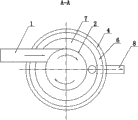
Fig. 2 is the A-A cross-sectional schematic of Fig. 1.
Among the figure: pulp-inlet pipe 1, whirl cylinder 2, annular overflow plate 3, water delivery chamber 4, with one heart bevel-type sand sediment pipe 5, clear liquid chamber 6, annular water collecting dike 7, outlet pipe 8, thick slag bucket 9, thin slag bucket 10, mud concentration tube 11, slag notch valve 12, bottom bracket 13, the first cylindrical shells 14, the second cylindrical shells 15.
The specific embodiment
In Fig. 1, a kind of body refuse treating apparatus for pressure type water-pumping/draining exit comprises that the first cylindrical shell 14, the first cylindrical shells 14 bottoms are provided with thin slag bucket 10,10 one-tenth top little tapers in the large end of thin slag bucket, and thin slag bucket 10 bottoms are provided with mud concentration tube 11;
The second cylindrical shell 15 is installed in the first cylindrical shell 14, forms water delivery chamber 4 between the second cylindrical shell 15 and the first cylindrical shell 14; In the water delivery chamber, liquid flows from top to bottom.
Top between whirl cylinder 2 and the second cylindrical shell 15 is provided with clear liquid chamber 6, and the bottom is provided with the concentric bevel-type sand sediment pipe 5 that is communicated with clear liquid chamber 6.In the scheme of optimizing, described concentric bevel-type sand sediment pipe 5 is the conically shaped of a plurality of arranged concentric.Described concentric bevel-type sand sediment pipe 5 is positioned at the position of the outer wall of thick slag bucket 9.In the scheme of further optimizing, described conically shaped is multilayer, and spacing is consistent between each layer, and the conically shaped in this example is three layers.Concentric bevel-type sand sediment pipe 5 in this example has creatively used tube settling and shallow pond precipitation principle, and for example: establishing the tube settler pond long highly is H for L, and horizontal flow velocity is v in the pond, and the heavy speed of particle is u0, in the ideal situation, and L/H=v/ u0.When as seen L and v value were constant, the pond body was more shallow, and is can removed suspended particle less.If use horizontal baffle, H is divided into 3 layers, whenever be H/3 layer by layer deeply, under the constant condition of u0 and v, only need L/3, just can be with the particle removal of u0.Also be that total measurement (volume) can reduce to original 1/3.If the pond is long constant, because the pond be H/3 deeply, then horizontal flow velocity can increase to 3v, still can remove for the particle of u0 sinking speed, and also soon sedimentation basin is divided into the n layer and just can improves n times to disposal ability.And adopt three layers of bevel-type sand sediment pipe 5 that arrange with one heart in this example, in the highly constant situation of whole device, realized the combination that tube settling and shallow pond are precipitated.
Be provided with the annular water collecting dike 7 that the top is communicated with clear liquid chamber 6 in the clear liquid chamber 6, the bottom of annular water collecting dike 7 is provided with outlet pipe 8; Water after the separation is discharged from from outlet pipe 8, thereby has effectively reduced environmental pollution.
Pulp-inlet pipe 1 passes the first cylindrical shell 14, the second cylindrical shell 15 and annular water collecting dike 7 and is communicated with whirl cylinder 2.In the scheme of optimizing, as shown in Figure 2, the mode with the barrel inscribe between pulp-inlet pipe 1 and the whirl cylinder 2 is communicated with.Structure has realized the cyclonic separation function at whirl cylinder 2 thus.
Described mud concentration tube 11 is provided with slag notch valve 12.Described the first cylindrical shell 14 bottoms are provided with bottom bracket 13.
As shown in fig. 1, during use, the liquid of pumping drainage pipe outlet enters whirl cylinder 2 by pulp-inlet pipe 1, cut intersects in the barrel of the tube wall of pulp-inlet pipe 1 and whirl cylinder 2, make liquid in whirl cylinder 2 interior rotations, because the density of slag and liquid is different, the slag that density is large sinks down into thick slag bucket 9, thick slag bucket 9 is up big and down small, is convenient to body refuse downslide and concentrated.The concentric bevel-type sand sediment pipe 5 that also helps with its outer wall position makes up installation.
Contain the liquid of the less granule slag of density through overflow plate 3, entering the 4 rear changes of water delivery chamber flows to, low speed passes through the concentric bevel-type sand sediment pipe 5 of multilayer from bottom to up, the number of plies of bevel-type sand sediment pipe 5 is more with one heart, liquid flows from bottom to top at each interlayer, to have reduced settling height to each layer body refuse, the sedimentation of having accelerated body refuse.Little large under the conically shaped, liquid flows from bottom to top, and flow velocity further descends, and has further promoted the sedimentation of body refuse.
Liquid continues to make progress to clear liquid chamber 6, and the mode with overflow enters annular water collecting dike 7 again, discharges by the outlet pipe 8 of annular water collecting dike 7 bottoms at last; The fine grained body refuse enters thin slag bucket 10 by the tube wall downslide of concentric bevel-type sand sediment pipe 5.Slightly, the fine grained body refuse concentrated in thick slag bucket 9 and thin slag bucket 10 respectively after, it is further concentrated to enter mud concentration tube 11.Body refuse after concentrated is regularly discharged by slag notch valve 12.Realize thus the effect that slag liquid separates.
Claims (8)
1. a body refuse treating apparatus that is used for pressure type water-pumping/draining exit comprises the first cylindrical shell (14), and it is characterized in that: the first cylindrical shell (14) bottom is provided with thin slag bucket (10), and thin slag bucket (10) bottom is provided with mud concentration tube (11);
The second cylindrical shell (15) is installed in the first cylindrical shell (14), forms water delivery chamber (4) between the second cylindrical shell (15) and the first cylindrical shell (14);
Whirl cylinder (2) is installed in the second cylindrical shell (15), whirl cylinder (2) bottom is provided with the thick slag bucket (9) that is communicated to thin slag bucket (10), whirl cylinder (2) is connected by annular overflow plate (3) with the top of the second cylindrical shell (15), top between whirl cylinder (2) and the second cylindrical shell (15) is provided with clear liquid chamber (6), the bottom is provided with the concentric bevel-type sand sediment pipe (5) that is communicated with clear liquid chamber (6), be provided with the annular water collecting dike (7) that the top is communicated with clear liquid chamber (6) in the clear liquid chamber (6), the bottom of annular water collecting dike (7) is provided with outlet pipe (8);
Pulp-inlet pipe (1) passes the first cylindrical shell (14), the second cylindrical shell (15) and annular water collecting dike (7) and is communicated with whirl cylinder (2).
2. a kind of body refuse treating apparatus for pressure type water-pumping/draining exit according to claim 1 is characterized in that: the mode with the barrel inscribe between pulp-inlet pipe (1) and the whirl cylinder (2) is communicated with.
3. a kind of body refuse treating apparatus for pressure type water-pumping/draining exit according to claim 1, it is characterized in that: described concentric bevel-type sand sediment pipe (5) is the conically shaped of a plurality of arranged concentric.
4. a kind of body refuse treating apparatus for pressure type water-pumping/draining exit according to claim 3, it is characterized in that: described concentric bevel-type sand sediment pipe (5) is positioned at the position of the outer wall of thick slag bucket (9).
5. a kind of body refuse treating apparatus for pressure type water-pumping/draining exit according to claim 3, it is characterized in that: described conically shaped is multilayer.
6. a kind of body refuse treating apparatus for pressure type water-pumping/draining exit according to claim 1 is characterized in that: described annular overflow plate (3) is higher near an end in the center of circle, and lower away from an end in the center of circle.
7. a kind of body refuse treating apparatus for pressure type water-pumping/draining exit according to claim 1, it is characterized in that: described mud concentration tube (11) is provided with slag notch valve (12).
8. a kind of body refuse treating apparatus for pressure type water-pumping/draining exit according to claim 1 is characterized in that: be provided with bottom bracket (13) bottom described the first cylindrical shell (14).
Priority Applications (1)
| Application Number | Priority Date | Filing Date | Title |
|---|---|---|---|
| CN 201220371041 CN202700154U (en) | 2012-07-30 | 2012-07-30 | Sludge treatment device at pressure type water pumping and drainage outlet |
Applications Claiming Priority (1)
| Application Number | Priority Date | Filing Date | Title |
|---|---|---|---|
| CN 201220371041 CN202700154U (en) | 2012-07-30 | 2012-07-30 | Sludge treatment device at pressure type water pumping and drainage outlet |
Publications (1)
| Publication Number | Publication Date |
|---|---|
| CN202700154U true CN202700154U (en) | 2013-01-30 |
Family
ID=47580496
Family Applications (1)
| Application Number | Title | Priority Date | Filing Date |
|---|---|---|---|
| CN 201220371041 Expired - Fee Related CN202700154U (en) | 2012-07-30 | 2012-07-30 | Sludge treatment device at pressure type water pumping and drainage outlet |
Country Status (1)
| Country | Link |
|---|---|
| CN (1) | CN202700154U (en) |
Cited By (3)
| Publication number | Priority date | Publication date | Assignee | Title |
|---|---|---|---|---|
| CN102755768A (en) * | 2012-07-30 | 2012-10-31 | 葛洲坝集团第一工程有限公司 | Sludge treatment device used at pressure type pumping and drainage outlet |
| CN104162295A (en) * | 2013-05-17 | 2014-11-26 | 颜可仁 | Sedimentation type mud and sand separator |
| CN107188331A (en) * | 2017-06-04 | 2017-09-22 | 江苏沃尔特环保有限公司 | A kind of new River water purification system |
-
2012
- 2012-07-30 CN CN 201220371041 patent/CN202700154U/en not_active Expired - Fee Related
Cited By (4)
| Publication number | Priority date | Publication date | Assignee | Title |
|---|---|---|---|---|
| CN102755768A (en) * | 2012-07-30 | 2012-10-31 | 葛洲坝集团第一工程有限公司 | Sludge treatment device used at pressure type pumping and drainage outlet |
| CN102755768B (en) * | 2012-07-30 | 2015-06-17 | 葛洲坝集团第一工程有限公司 | Sludge treatment device used at pressure type pumping and drainage outlet |
| CN104162295A (en) * | 2013-05-17 | 2014-11-26 | 颜可仁 | Sedimentation type mud and sand separator |
| CN107188331A (en) * | 2017-06-04 | 2017-09-22 | 江苏沃尔特环保有限公司 | A kind of new River water purification system |
Similar Documents
| Publication | Publication Date | Title |
|---|---|---|
| CN102755768B (en) | Sludge treatment device used at pressure type pumping and drainage outlet | |
| CN201932932U (en) | Mud-water separating device used for sewage disposal | |
| CN109052558A (en) | A kind of cyclone air-flotation separator | |
| CN210698952U (en) | Silt whirl deposits device suitable for sewage purification handles | |
| CN202700154U (en) | Sludge treatment device at pressure type water pumping and drainage outlet | |
| CN101423262A (en) | Air-floated water treating apparatus | |
| CN105668740A (en) | Integrated sand washing waste water reuse device | |
| CN111330317A (en) | Efficient sewage precipitation device and method | |
| CN201842724U (en) | Combined clarifier | |
| JP4009180B2 (en) | Suspended water separation treatment system | |
| CN207347304U (en) | A kind of coal-contained wastewater processing system | |
| CN206395925U (en) | Deliming anaerobic reactor | |
| CN2536583Y (en) | Cyclonic sand settling devices | |
| CN103990302A (en) | Radial flow sedimentation device | |
| CN2345265Y (en) | Sewage purifier | |
| CN207468255U (en) | A kind of Horizontal oil-water separator | |
| CN206624732U (en) | A kind of efficient oil-contained waste water treatment device | |
| CN109354246A (en) | A kind of high-concentration sewage quick treatment device and its processing method | |
| CN205590382U (en) | Integration washed -out sand waste water recycling device | |
| CN107814431A (en) | A kind of recyclable oil-contained waste water treatment device | |
| CN205516881U (en) | Strengthen superposed layer spiral vertical flow settling pond | |
| CN211836486U (en) | Cyclone separator | |
| CN209226738U (en) | A kind of high-concentration sewage quick treatment device | |
| CN207996462U (en) | A kind of setting tablet device for separating mud and water | |
| CN206463554U (en) | A kind of high-efficiency swirl-type second pond |
Legal Events
| Date | Code | Title | Description |
|---|---|---|---|
| C14 | Grant of patent or utility model | ||
| GR01 | Patent grant | ||
| CF01 | Termination of patent right due to non-payment of annual fee |
Granted publication date: 20130130 Termination date: 20180730 |
|
| CF01 | Termination of patent right due to non-payment of annual fee |