CN102755768A - Sludge treatment device used at pressure type pumping and drainage outlet - Google Patents
Sludge treatment device used at pressure type pumping and drainage outlet Download PDFInfo
- Publication number
- CN102755768A CN102755768A CN201210265587XA CN201210265587A CN102755768A CN 102755768 A CN102755768 A CN 102755768A CN 201210265587X A CN201210265587X A CN 201210265587XA CN 201210265587 A CN201210265587 A CN 201210265587A CN 102755768 A CN102755768 A CN 102755768A
- Authority
- CN
- China
- Prior art keywords
- cylinder
- cylindrical shell
- pressure type
- communicated
- body refuse
- Prior art date
- Legal status (The legal status is an assumption and is not a legal conclusion. Google has not performed a legal analysis and makes no representation as to the accuracy of the status listed.)
- Granted
Links
- 239000010802 sludge Substances 0.000 title abstract description 10
- 238000005086 pumping Methods 0.000 title abstract 2
- 239000007788 liquid Substances 0.000 claims abstract description 32
- XLYOFNOQVPJJNP-UHFFFAOYSA-N water Substances O XLYOFNOQVPJJNP-UHFFFAOYSA-N 0.000 claims abstract description 28
- 239000004576 sand Substances 0.000 claims abstract description 18
- 239000002893 slag Substances 0.000 claims description 32
- 239000003657 drainage water Substances 0.000 claims description 17
- 239000013049 sediment Substances 0.000 claims description 16
- 230000000694 effects Effects 0.000 abstract description 6
- 238000000926 separation method Methods 0.000 abstract description 6
- 238000003912 environmental pollution Methods 0.000 abstract description 4
- 238000001556 precipitation Methods 0.000 abstract 1
- 239000002002 slurry Substances 0.000 abstract 1
- 239000010410 layer Substances 0.000 description 8
- 239000002245 particle Substances 0.000 description 6
- 238000004062 sedimentation Methods 0.000 description 4
- 239000012141 concentrate Substances 0.000 description 2
- 238000007599 discharging Methods 0.000 description 2
- 238000005516 engineering process Methods 0.000 description 2
- 238000005189 flocculation Methods 0.000 description 2
- 230000016615 flocculation Effects 0.000 description 2
- 239000007787 solid Substances 0.000 description 2
- 238000010276 construction Methods 0.000 description 1
- 230000008021 deposition Effects 0.000 description 1
- 239000008187 granular material Substances 0.000 description 1
- 239000003673 groundwater Substances 0.000 description 1
- 239000011229 interlayer Substances 0.000 description 1
- 238000005259 measurement Methods 0.000 description 1
- 238000000034 method Methods 0.000 description 1
- 239000002351 wastewater Substances 0.000 description 1
Images

Landscapes
- Cyclones (AREA)
- Treatment Of Sludge (AREA)
Abstract
The invention discloses a sludge treatment device used at a pressure type pumping and drainage outlet. The sludge treatment device comprises a first cylinder, wherein the lower part of the first cylinder is provided with a fine sludge hopper; the lower part of the fine sludge hopper is provided with a sludge concentration pipe; a second cylinder is arranged in the first cylinder; a water conveying cavity is formed between the second cylinder and the first cylinder; a cyclone cylinder is arranged in the second cylinder; the lower part of the cyclone cylinder is provided with a coarse sludge hopper which is communicated with the fine sludge hopper; the cyclone cylinder is connected with the top end of the second cylinder through an annular overflow plate; the upper part between the cyclone cylinder and the second cylinder is provided with a clear liquid cavity, and the lower part between the cyclone cylinder and the second cylinder is provided with a concentric tapered sand setting pipe which is communicated with the clear liquid cavity; an annular catchment weir of which the top is communicated with the clear liquid cavity is arranged in the clear liquid cavity; the bottom of the annular catchment weir is provided with a water outlet pipe; and a slurry inlet pipe passes through the first cylinder and the second cylinder to be communicated with the cyclone cylinder. By using cyclone separation and a combined scheme of leaning pipe precipitation and overflow catchment, separation of water and sludge can be realized without extra power or a flocculant, the separation effect is excellent, and environmental pollution is reduced.
Description
Technical field
The present invention relates to body refuse and handle separating treatment field, especially a kind of motorless body refuse treating apparatus that is used for pressure type pump drainage water out place.
Background technology
Under most situation, the outlet of pressure type pump drainage waterpipe exists certain flow velocity and kinetic energy, contains a large amount of solids in these liquid that are discharged from sometimes, in case directly discharging often causes environmental pollution.
In the engineering construction process, often be accompanied by draining, especially in the riverbed, when construct in river course and the higher area of level of ground water, more be unable to do without the pump drainage water conservancy project and do.And present pump drainage water conservancy project work all is to utilize water pump to carry out usually, often carries a large amount of silt particles during pump drainage water secretly, and these contain the often directly discharging of waste water of a large amount of silt particles, also pollute.
Chinese patent 201110080437.7 discloses backflow muddy water device for effectively separating in a kind of pipe/cartridge type body refuse; Mechanical flocculation zone through being provided with is realized separating of body refuse and water with waterpower flocculation zone, settling zone, active mud enrichment region, impeller lifting device; But need the extra power that provides, and body refuse and water separate the effect realization that mainly still relies on flocculant.Whole height of devices is higher, is unfavorable for installing.
Chinese patent 201120357703.1 provides a kind of equipment for separating liquid from solid that efficiently drifts along, and scum and sink mud through the mode that adopts air dissolved pump and overflow to catchment, but adopt the extra power of air dissolved pump needs, and body refuse sedimentation effect of the present invention is not good.
Summary of the invention
Technical problem to be solved by this invention provides a kind of body refuse treating apparatus that is used for pressure type pump drainage water out place, and the mode that can need not extra additional power is divided dried up and body refuse, and separating effect is preferable.Further, also need not to add flocculant and can realize separating of water and body refuse.
For solving the problems of the technologies described above, the technical scheme that the present invention adopted is: a kind of body refuse treating apparatus that is used for pressure type pump drainage water out place, comprise first cylindrical shell, and the first cylindrical shell bottom is provided with thin slag bucket, and thin slag bucket bottom is provided with the mud concentration tube;
Second cylindrical shell is installed in first cylindrical shell, forms the water delivery chamber between second cylindrical shell and first cylindrical shell;
Whirl cylinder is installed in second cylindrical shell; The whirl cylinder bottom is provided with the thick slag bucket that is communicated to thin slag bucket; Whirl cylinder is connected through annular overflow plate with the top of second cylindrical shell, and the top between the whirl cylinder and second cylindrical shell is provided with the clear liquid chamber, and the bottom is provided with the concentric bevel-type sand sediment pipe that is communicated with the clear liquid chamber; Be provided with the annular water collecting dike that the top is communicated with the clear liquid chamber in the clear liquid chamber, the bottom of annular water collecting dike is provided with outlet pipe;
Pulp-inlet pipe passes first cylindrical shell, second cylindrical shell and annular water collecting dike and is communicated with whirl cylinder.
Mode with the barrel inscribe between pulp-inlet pipe and the whirl cylinder is communicated with.
The conically shaped that described concentric bevel-type sand sediment pipe is a plurality of arranged concentric.
Described concentric bevel-type sand sediment pipe is positioned at the position of the outer wall of thick slag bucket.
Described conically shaped is a multilayer.
Described annular overflow plate is higher near an end in the center of circle, and lower away from an end in the center of circle.
Described mud concentration tube is provided with the slag notch valve.
Described first cylindrical shell bottom is provided with bottom bracket.
A kind of body refuse treating apparatus that is used for pressure type pump drainage water out place provided by the invention; Through the assembled scheme that adopts cyclonic separation, tube settling and overflow to catchment; Need not extra power, need not to add flocculant and promptly realized separating of water and body refuse, and separating effect is preferable.Device of the present invention makes full use of the kinetic energy of pressure type pump drainage pipe outlet liquid, impels slag liquid to separate, and has reduced environmental pollution.
Description of drawings
Below in conjunction with accompanying drawing and embodiment the present invention is described further:
Fig. 1 is an overall structure sketch map of the present invention, and the arrow among the figure is a liquid flow direction.
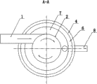
Fig. 2 is the A-A cross-sectional schematic of Fig. 1.
Among the figure: pulp-inlet pipe 1, whirl cylinder 2, annular overflow plate 3, water delivery chamber 4, bevel-type sand sediment pipe 5 with one heart; Clear liquid chamber 6, annular water collecting dike 7, outlet pipe 8, thick slag bucket 9, thin slag bucket 10; Mud concentration tube 11, slag notch valve 12, bottom bracket 13, the first cylindrical shells 14, the second cylindrical shells 15.
The specific embodiment
In Fig. 1, a kind of body refuse treating apparatus that is used for pressure type pump drainage water out place comprises that first cylindrical shell, 14, the first cylindrical shells, 14 bottoms are provided with thin slag bucket 10,10 one-tenth top little tapers in the big end of thin slag bucket, and thin slag bucket 10 bottoms are provided with mud concentration tube 11;
Second cylindrical shell 15 is installed in first cylindrical shell 14, forms water delivery chamber 4 between second cylindrical shell 15 and first cylindrical shell 14; In the water delivery chamber, liquid flows from top to bottom.
Top between the whirl cylinder 2 and second cylindrical shell 15 is provided with clear liquid chamber 6, and the bottom is provided with the concentric bevel-type sand sediment pipe 5 that is communicated with clear liquid chamber 6.In the scheme of optimizing, described concentric bevel-type sand sediment pipe 5 is the conically shaped of a plurality of arranged concentric.Described concentric bevel-type sand sediment pipe 5 is positioned at the position of the outer wall of thick slag bucket 9.In the scheme of further optimizing, described conically shaped is a multilayer, and spacing is consistent between each layer, and the conically shaped in this example is three layers.Concentric bevel-type sand sediment pipe 5 in this example has creatively used tube settling and shallow pond deposition principle, and for example: establishing the tube settler pond long highly is H for L, and horizontal flow velocity is V in the pond, and the heavy speed of particle is u0, under perfect condition, and L/H=V/ u0.It is thus clear that it is when L and V value were constant, the pond body was shallow more, can removed suspended particle more little.If use horizontal baffle, H is divided into 3 layers, whenever be H/3 layer by layer deeply, under the constant condition of u0 and v, a need L/3 just can be with the particle removal of u0.Also be that total measurement (volume) can reduce to original 1/3.If the pond is long constant, because the pond be H/3 deeply, the 3v that then horizontal flow velocity can just add still can remove for the particle of u0 sinking speed, and also soon sedimentation basin is divided into the n layer and just can improves n times to disposal ability.And adopt three layers of bevel-type sand sediment pipe 5 that are provided with one heart in this example, under the highly constant situation of whole device, realized that tube settling combines with shallow pond is precipitated.
Be provided with the annular water collecting dike 7 that the top is communicated with clear liquid chamber 6 in the clear liquid chamber 6, the bottom of annular water collecting dike 7 is provided with outlet pipe 8; Water after the separation is discharged from from outlet pipe 8, thereby has effectively reduced environmental pollution.
Pulp-inlet pipe 1 passes first cylindrical shell 14, second cylindrical shell 15 and annular water collecting dike 7 and is communicated with whirl cylinder 2.In the scheme of optimizing, as shown in Figure 2, the mode with the barrel inscribe between pulp-inlet pipe 1 and the whirl cylinder 2 is communicated with.Structure has realized the cyclonic separation function at whirl cylinder 2 thus.
Described mud concentration tube 11 is provided with slag notch valve 12.Described first cylindrical shell 14 bottoms are provided with bottom bracket 13.
As shown in fig. 1, during use, the liquid of pump drainage pipe outlet gets into whirl cylinder 2 through pulp-inlet pipe 1; Cut intersects in the barrel of the tube wall of pulp-inlet pipe 1 and whirl cylinder 2; Liquid is rotated in whirl cylinder 2, because slag is different with density of liquid, the slag that density is big sinks down into thick slag bucket 9; Thick slag bucket 9 is up big and down small, is convenient to body refuse downslide and concentrated.The concentric bevel-type sand sediment pipe 5 that also helps with its outer wall position carries out aggregate erection.
The liquid that contains the less granule slag of density is through overflow plate 3; Get into 4 backs, water delivery chamber and change the flow direction; Through the concentric bevel-type sand sediment pipe 5 of multilayer, the number of plies of bevel-type sand sediment pipe 5 is more with one heart from bottom to up for low speed, and liquid flows at each interlayer from bottom to top; To each layer body refuse is to have reduced settling height, the sedimentation of having quickened body refuse.Little going up greatly under the conically shaped, liquid flows from bottom to top, and flow velocity further descends, and has further promoted the sedimentation of body refuse.
Liquid continues to make progress to clear liquid chamber 6, and the mode with overflow gets into annular water collecting dike 7 again, discharges through the outlet pipe 8 of annular water collecting dike 7 bottoms at last; The fine grained body refuse gets into thin slag bucket 10 through the tube wall downslide of concentric bevel-type sand sediment pipe 5.Slightly, after the fine grained body refuse concentrates in sand collecting hopper 9 and sludge hopper 10 respectively, get into mud concentration tube 11 and further concentrate.Body refuse after concentrating is regularly discharged through slag notch valve 12.Realize the effect that slag liquid separates thus.
Claims (8)
1. a body refuse treating apparatus that is used for pressure type pump drainage water out place comprises first cylindrical shell (14), it is characterized in that: first cylindrical shell (14) bottom is provided with thin slag bucket (10), and thin slag bucket (10) bottom is provided with mud concentration tube (11);
Second cylindrical shell (15) is installed in first cylindrical shell (14), forms water delivery chamber (4) between second cylindrical shell (15) and first cylindrical shell (14);
Whirl cylinder (2) is installed in second cylindrical shell (15); Whirl cylinder (2) bottom is provided with the thick slag bucket (9) that is communicated to thin slag bucket (10); Whirl cylinder (2) is connected through annular overflow plate (3) with the top of second cylindrical shell (15); Top between whirl cylinder (2) and second cylindrical shell (15) is provided with clear liquid chamber (6); The bottom is provided with the concentric bevel-type sand sediment pipe (5) that is communicated with clear liquid chamber (6), is provided with the annular water collecting dike (7) that the top is communicated with clear liquid chamber (6) in clear liquid chamber (6), and the bottom of annular water collecting dike (7) is provided with outlet pipe (8);
Pulp-inlet pipe (1) passes first cylindrical shell (14), second cylindrical shell (15) and annular water collecting dike (7) and is communicated with whirl cylinder (2).
2. a kind of body refuse treating apparatus that is used for pressure type pump drainage water out place according to claim 1 is characterized in that: the mode with the barrel inscribe between pulp-inlet pipe (1) and the whirl cylinder (2) is communicated with.
3. a kind of body refuse treating apparatus that is used for pressure type pump drainage water out place according to claim 1, it is characterized in that: described concentric bevel-type sand sediment pipe (5) is the conically shaped of a plurality of arranged concentric.
4. a kind of body refuse treating apparatus that is used for pressure type pump drainage water out place according to claim 3, it is characterized in that: described concentric bevel-type sand sediment pipe (5) is positioned at the position of the outer wall of thick slag bucket (9).
5. a kind of body refuse treating apparatus that is used for pressure type pump drainage water out place according to claim 3, it is characterized in that: described conically shaped is a multilayer.
6. a kind of body refuse treating apparatus that is used for pressure type pump drainage water out place according to claim 1, it is characterized in that: described annular overflow plate (3) is higher near an end in the center of circle, and lower away from an end in the center of circle.
7. a kind of body refuse treating apparatus that is used for pressure type pump drainage water out place according to claim 1, it is characterized in that: described mud concentration tube (11) is provided with slag notch valve (12).
8. a kind of body refuse treating apparatus that is used for pressure type pump drainage water out place according to claim 1 is characterized in that: described first cylindrical shell (14) bottom is provided with bottom bracket (13).
Priority Applications (1)
| Application Number | Priority Date | Filing Date | Title |
|---|---|---|---|
| CN201210265587.XA CN102755768B (en) | 2012-07-30 | 2012-07-30 | Sludge treatment device used at pressure type pumping and drainage outlet |
Applications Claiming Priority (1)
| Application Number | Priority Date | Filing Date | Title |
|---|---|---|---|
| CN201210265587.XA CN102755768B (en) | 2012-07-30 | 2012-07-30 | Sludge treatment device used at pressure type pumping and drainage outlet |
Publications (2)
| Publication Number | Publication Date |
|---|---|
| CN102755768A true CN102755768A (en) | 2012-10-31 |
| CN102755768B CN102755768B (en) | 2015-06-17 |
Family
ID=47050562
Family Applications (1)
| Application Number | Title | Priority Date | Filing Date |
|---|---|---|---|
| CN201210265587.XA Expired - Fee Related CN102755768B (en) | 2012-07-30 | 2012-07-30 | Sludge treatment device used at pressure type pumping and drainage outlet |
Country Status (1)
| Country | Link |
|---|---|
| CN (1) | CN102755768B (en) |
Cited By (7)
| Publication number | Priority date | Publication date | Assignee | Title |
|---|---|---|---|---|
| CN102940983A (en) * | 2012-11-28 | 2013-02-27 | 常州江南电力环境工程有限公司 | Defecator for desulfurization wastewater treatment |
| CN104623934A (en) * | 2013-11-08 | 2015-05-20 | 中冶长天国际工程有限责任公司 | Pre-grading thickener |
| CN105396337A (en) * | 2014-09-09 | 2016-03-16 | 宜兴市天马环保工程有限公司 | Novel swirling flow precipitator |
| CN106422433A (en) * | 2016-09-23 | 2017-02-22 | 苏州市浒墅关化工添加剂有限公司 | Solvent-based dinonyl-naphthalenesulfonic acid barium layered continuous sedimentation tank |
| CN108238662A (en) * | 2016-12-23 | 2018-07-03 | 中国石油天然气股份有限公司 | Reinforced cyclone sand setting tank |
| CN109485171A (en) * | 2018-12-29 | 2019-03-19 | 广州创领水产科技有限公司 | A kind of breeding wastewater recovery processing reutilization technology and system |
| CN110342608A (en) * | 2019-05-27 | 2019-10-18 | 安徽理工大学 | A kind of compound concentration and settlement device of cyclone classification formula |
Citations (6)
| Publication number | Priority date | Publication date | Assignee | Title |
|---|---|---|---|---|
| JP2003019403A (en) * | 2001-07-10 | 2003-01-21 | Yoshikimi Watanabe | Jet stirring type solid-liquid separation apparatus |
| CN1806885A (en) * | 2005-12-15 | 2006-07-26 | 景兴 | Cone laminated concentric ring bevel deposition device |
| CN200951968Y (en) * | 2006-08-21 | 2007-09-26 | 何公亮 | Drum slot structure with multiple vortex water purification |
| CN201809212U (en) * | 2010-09-01 | 2011-04-27 | 中冶东方工程技术有限公司 | Magnetic cyclone clarifier |
| CN202080969U (en) * | 2011-04-28 | 2011-12-21 | 秦皇岛莱特流体设备制造有限公司 | Efficient combined water purifier |
| CN202700154U (en) * | 2012-07-30 | 2013-01-30 | 葛洲坝集团第一工程有限公司 | Sludge treatment device at pressure type water pumping and drainage outlet |
-
2012
- 2012-07-30 CN CN201210265587.XA patent/CN102755768B/en not_active Expired - Fee Related
Patent Citations (6)
| Publication number | Priority date | Publication date | Assignee | Title |
|---|---|---|---|---|
| JP2003019403A (en) * | 2001-07-10 | 2003-01-21 | Yoshikimi Watanabe | Jet stirring type solid-liquid separation apparatus |
| CN1806885A (en) * | 2005-12-15 | 2006-07-26 | 景兴 | Cone laminated concentric ring bevel deposition device |
| CN200951968Y (en) * | 2006-08-21 | 2007-09-26 | 何公亮 | Drum slot structure with multiple vortex water purification |
| CN201809212U (en) * | 2010-09-01 | 2011-04-27 | 中冶东方工程技术有限公司 | Magnetic cyclone clarifier |
| CN202080969U (en) * | 2011-04-28 | 2011-12-21 | 秦皇岛莱特流体设备制造有限公司 | Efficient combined water purifier |
| CN202700154U (en) * | 2012-07-30 | 2013-01-30 | 葛洲坝集团第一工程有限公司 | Sludge treatment device at pressure type water pumping and drainage outlet |
Cited By (10)
| Publication number | Priority date | Publication date | Assignee | Title |
|---|---|---|---|---|
| CN102940983A (en) * | 2012-11-28 | 2013-02-27 | 常州江南电力环境工程有限公司 | Defecator for desulfurization wastewater treatment |
| CN104623934A (en) * | 2013-11-08 | 2015-05-20 | 中冶长天国际工程有限责任公司 | Pre-grading thickener |
| CN104623934B (en) * | 2013-11-08 | 2017-02-01 | 中冶长天国际工程有限责任公司 | Pre-grading thickener |
| CN105396337A (en) * | 2014-09-09 | 2016-03-16 | 宜兴市天马环保工程有限公司 | Novel swirling flow precipitator |
| CN105396337B (en) * | 2014-09-09 | 2017-05-17 | 宜兴市天马环保工程有限公司 | Novel swirling flow precipitator |
| CN106422433A (en) * | 2016-09-23 | 2017-02-22 | 苏州市浒墅关化工添加剂有限公司 | Solvent-based dinonyl-naphthalenesulfonic acid barium layered continuous sedimentation tank |
| CN108238662A (en) * | 2016-12-23 | 2018-07-03 | 中国石油天然气股份有限公司 | Reinforced cyclone sand setting tank |
| CN108238662B (en) * | 2016-12-23 | 2021-01-01 | 中国石油天然气股份有限公司 | Reinforced cyclone sand setting tank |
| CN109485171A (en) * | 2018-12-29 | 2019-03-19 | 广州创领水产科技有限公司 | A kind of breeding wastewater recovery processing reutilization technology and system |
| CN110342608A (en) * | 2019-05-27 | 2019-10-18 | 安徽理工大学 | A kind of compound concentration and settlement device of cyclone classification formula |
Also Published As
| Publication number | Publication date |
|---|---|
| CN102755768B (en) | 2015-06-17 |
Similar Documents
| Publication | Publication Date | Title |
|---|---|---|
| CN102755768B (en) | Sludge treatment device used at pressure type pumping and drainage outlet | |
| CN205774033U (en) | A kind of compound efficient depositing reservoir | |
| CN105836932A (en) | Method for treating wastewater containing sediment | |
| CN201932932U (en) | Mud-water separating device used for sewage disposal | |
| CN202446874U (en) | Hydraulic cyclone sand setting device | |
| CN106698624A (en) | Dielectric-accelerated high-density sedimentation tank water treatment system and process | |
| CN104230123B (en) | Remove the device of inorganic particle in Sewage treatment systems | |
| CN215855430U (en) | High-efficiency rotational flow sewage purification device | |
| CN209537204U (en) | Magnetic loads water treatment facilities | |
| CN104193027A (en) | A gravity type integrated water purifier | |
| CN109052558A (en) | A kind of cyclone air-flotation separator | |
| CN111330317A (en) | Efficient sewage precipitation device and method | |
| CN210698952U (en) | Silt whirl deposits device suitable for sewage purification handles | |
| CN109879467B (en) | Sludge concentration and separation device for mine water treatment | |
| CN105668740A (en) | Integrated sand washing waste water reuse device | |
| CN208843831U (en) | A kind of central tube cyclonic separation settler | |
| CN202700154U (en) | Sludge treatment device at pressure type water pumping and drainage outlet | |
| CN201842724U (en) | Combined clarifier | |
| CN207347304U (en) | A kind of coal-contained wastewater processing system | |
| CN202246207U (en) | High-efficiency float and sediment solid-liquid separation device | |
| CN2345265Y (en) | Sewage purifier | |
| CN204699466U (en) | Gas stripping type desander for rotational flow grit pit | |
| CN205590382U (en) | Integration washed -out sand waste water recycling device | |
| CN211885522U (en) | High-efficient sewage precipitation device | |
| CN110876861B (en) | Horizontal mud-water separator |
Legal Events
| Date | Code | Title | Description |
|---|---|---|---|
| C06 | Publication | ||
| PB01 | Publication | ||
| C10 | Entry into substantive examination | ||
| SE01 | Entry into force of request for substantive examination | ||
| C14 | Grant of patent or utility model | ||
| GR01 | Patent grant | ||
| CF01 | Termination of patent right due to non-payment of annual fee |
Granted publication date: 20150617 |
|
| CF01 | Termination of patent right due to non-payment of annual fee |