CN202628654U - Swinging hydraulic cylinder - Google Patents
Swinging hydraulic cylinder Download PDFInfo
- Publication number
- CN202628654U CN202628654U CN 201220213633 CN201220213633U CN202628654U CN 202628654 U CN202628654 U CN 202628654U CN 201220213633 CN201220213633 CN 201220213633 CN 201220213633 U CN201220213633 U CN 201220213633U CN 202628654 U CN202628654 U CN 202628654U
- Authority
- CN
- China
- Prior art keywords
- output shaft
- shell body
- upper shell
- lower shell
- sleeve
- Prior art date
- Legal status (The legal status is an assumption and is not a legal conclusion. Google has not performed a legal analysis and makes no representation as to the accuracy of the status listed.)
- Withdrawn - After Issue
Links
Images


Abstract
The utility model relates to a swinging hydraulic cylinder which comprises an output shaft, a bearing, an upper shell body, a lower shell body, a slide sleeve, a guide sleeve and an adjusting seat; the upper shell body and the lower shell body are fastened through a bolt; the output shaft penetrates through the lower shell body and is rotationally arranged on the inner hole outer section of the upper shell body through the bearing; the slide sleeve loops the output shaft; the inner wall of the slide sleeve is connected with the output shaft; one section of the outer wall of the slide sleeve which is close to the upper shell body is connected with the inner wall of the upper shell body; the guide sleeve is fixedly arranged at the joint between the upper shell body and the lower shell body; the adjusting seat loops on the output shaft; the adjusting seat penetrates through the lower shell body and is screwed with the lower shell body; a part of the adjusting seat which is arranged in the lower shell body is connected with the inner wall of the lower shell body, and can rotate relative to the output shaft; a gap is left between the adjusting seat and the guide sleeve; and according to the swinging hydraulic cylinder, the structure is simple, the sealing performance is good, the processing precision is high, and the operation is easy.
Description
Technical field
The utility model relates to a kind of oil hydraulic cylinder, relates in particular to a kind of oscillating motor.
Background technique
At present oscillating motor all is to realize rotation and the swing of output shaft through gear rack, or adopts blade type to realize.
What utilize the rack-and-pinion realization is the circumferential turn that moves radially driven gear that utilizes tooth bar; Thereby realize the turn of output shaft; But in the middle of the high-precision applications field, need to increase in addition gap adjusting mechanism, to eliminate the rotation error that causes owing to machining accuracy more; Complex operation, inefficiency.
What adopt that blade type realizes is to adopt the gear rack automatic tool changer to realize, but it takes up room greatly, and component are many, and use middle gear tooth bar pair is easy to wear, and the rotary inertia of blade type is little and deposit the shortcoming of internal leakage.
Above-mentioned hydraulic cylinder structure is complicated, when inner member damages, and easy-maintaining not.
The model utility content
In view of this, be necessary to provide a kind of simple in structure, sealing is good and machining accuracy is high, easy-operating oscillating motor.
The utility model is to realize like this; A kind of oscillating motor comprises output shaft, bearing, upper shell, lower shell body, sliding sleeve, guide sleeve and adjustment seat, and said upper shell and said lower shell body pass through bolton; Said output shaft passes said lower shell body; And be rotatably installed in the outer section of endoporus of said upper shell through said bearing, the said output shaft of said sliding sleeve ring set, and the inwall of said sliding sleeve is provided with the gap near between one section of said upper shell and the said output shaft; Be connected with said output shaft away from a section of said upper shell; And the corresponding said output shaft in said gap is provided with helical teeth, the corresponding sliding sleeve inwall in said gap be provided with said output shaft on the helical teeth that is complementary of helical teeth, the helical teeth on the helical teeth of said sliding sleeve inwall and the said output shaft is meshing each other;
The outer wall of said sliding sleeve is connected with said upper enclosure inner wall near a section of said upper shell, and away from being provided with the gap between end of said upper shell and the said upper shell, the corresponding said sliding sleeve outer wall in said gap is provided with helical teeth;
Said guide sleeve is fixed on the joint of said upper shell and said lower shell body; And the inwall of said guide sleeve be provided with said sliding sleeve outer wall on the helical teeth that is complementary of said helical teeth, the helical teeth of the inwall of said guide sleeve is mutually meshing with the helical teeth of said sliding sleeve outer wall;
Said adjustment seat ring is placed on the said output shaft; Said adjustment seat passes said lower shell body; And be screwed with said lower shell body; Said adjustment seat is connected with said lower shell body inwall at said lower shell body interior section, and can have the gap between said adjustment seat and the said guide sleeve with respect to said output shaft rotation.
Further; In the said upper shell outer end of hole be provided with first and mandrel bearing sleeve and second and the mandrel bearing sleeve, said first and mandrel bearing sleeve ring set on said output shaft, and fastening with said output shaft; And said first and mandrel bearing sleeve side push against said bearing; Said second and the said output shaft of mandrel bearing sleeve ring set, and is connected, said second with said upper shell also edge, the outer wall place direction unidirectional extension parallel of mandrel bearing sleeve with its axis prop up said bearing.
Further, said second and the outer wall of mandrel bearing sleeve be provided with outside thread, the inwall outer end of said upper shell is provided with the internal thread that is complementary with said outside thread, said second and mandrel bearing sleeve and said upper shell be screwed.
Further, the joint of said upper shell and said lower shell body is provided with collar extension groove or the square collar extension groove with radian, and is provided with the protruding ring that is complementary with said radian collar extension groove or square collar extension groove at the outer wall of said guide sleeve.
Further, be equipped with seal ring between said guide sleeve outer wall and said upper shell and the said lower shell body.
Further, said sliding sleeve outer wall and said upper shell joint are provided with seal ring, and said sliding sleeve inwall and said output shaft joint are provided with seal ring.
Further, said adjustment seat outer wall is provided with seal ring with said lower shell body joint, and a said adjustment inwall and said output shaft joint are provided with seal ring.
Further, said second and mandrel bearing sleeve and said output shaft attachment portion be provided with seal ring.
Further, said upper shell is provided with filler opening and oil outlet, and said filler opening all is communicated with the inner chamber of said oscillating motor with said oil outlet, and said filler opening and said oil outlet are located at the both sides of said sliding sleeve and said upper shell joint respectively.
Further, said adjustment seat is provided with locking nut, and said locking nut is positioned at the joint of said adjustment seat and said lower shell body, and is positioned at said lower shell body outside, is close to said lower shell body.
The advantage of the oscillating motor that the utility model provides is: through sliding sleeve and guide sleeve are set, and at the inner and outer wall of sliding sleeve helical teeth is set on output shaft, on said output shaft, helical teeth is set; Said sliding sleeve and said output shaft are meshing each other, and said sliding sleeve and said guide sleeve are meshing each other, through the effect of oil pressure; Said sliding sleeve is promoted to said guide sleeve direction,, the horizontal motion of said sliding sleeve is changed into rotatablely moving of said output shaft through the effect of helical teeth; The helical teeth of said guide sleeve serves as leading role; Make stable drive, outputting torsion is big, has improved the overall performance ratio of oil hydraulic cylinder.
Both sides through in said sliding sleeve and said upper shell joint are provided with filler opening and oil outlet, to oscillating motor power source are provided, and are giving the filler opening oil-feed; When oil outlet was fuel-displaced, output shaft rotated to a direction, was giving the oil outlet oil-feed; When filler opening is fuel-displaced; The output shaft counterrotating makes the two-way rotation of oscillating motor ability, solves real ability and strengthens.
Through locking nut and adjustment seat are set; And be provided with the gap between adjustment seat and the guide sleeve; Said adjustment seat is connected through the mode of being screwed together with said lower shell body, when output shaft angle of swing and actual angle have error, adjusts through rotation; The gap that changes between adjustment seat and the guide sleeve reduces error, improves the practicability of oscillating motor.
Through be provided with first and mandrel bearing sleeve and second and the mandrel bearing sleeve in the upper shell outer end; Rigid bearing; Improve the tightness degree of oscillating motor, and said second and the mandrel bearing sleeve be connected through the screw thread mode of being screwed together with said upper shell, be convenient to remove and install and keep in repair.
Through in the joint of joint, guide sleeve and the upper shell of joint, sliding sleeve and the output shaft of sliding sleeve and upper shell and lower shell body, the joint and second of the joint of adjustment seat and lower shell body, adjustment seat and output shaft also all is provided with seal ring in the joint of mandrel bearing sleeve and output shaft, increased the sealability of oscillating motor inner chamber.
Through collar extension groove or the square collar extension groove with radian being set at upper shell and lower shell body joint; And the outer wall at said guide sleeve is provided with the protruding ring that is complementary with said radian collar extension groove or square collar extension groove; Increased the stationarity of guide sleeve, prevent guide sleeve rotation phenomenon generation and strengthened upper shell and the sealing of lower shell body joint.
The utility model is simple in structure, sealing is good and machining accuracy is high, easy-operating oscillating motor.
Description of drawings
Fig. 1 is the structural representation of the utility model oscillating motor.
Fig. 2 is upper shell and the sectional view of lower shell body stack mounting among Fig. 1.
Fig. 3 is the sectional view of the sliding sleeve among Fig. 1.
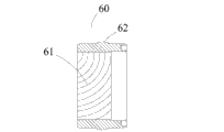
Fig. 4 is the sectional view of the guide sleeve among Fig. 1.
Fig. 5 is the sectional view of second among Fig. 1 and mandrel bearing sleeve.
Embodiment
For the purpose, technological scheme and the advantage that make the utility model is clearer,, the utility model is further elaborated below in conjunction with accompanying drawing and embodiment.Should be appreciated that specific embodiment described herein only in order to explanation the utility model, and be not used in qualification the utility model.
Please consult Fig. 1, Fig. 3 and Fig. 4 in the lump, wherein Fig. 1 is the structural representation of the utility model oscillating motor 100, and Fig. 3 is the sectional view of the sliding sleeve 50 among Fig. 1, and Fig. 4 is the sectional view of the guide sleeve 60 among Fig. 1.
Said oscillating motor 100 comprises output shaft 40, bearing 30, upper shell 10, lower shell body 20, sliding sleeve 50, guide sleeve 60 and adjustment seat 70; Said upper shell 10 is fastening through bolt 1 with said lower shell body 20; Said output shaft 40 passes said lower shell body 20; And be rotatably installed in the outer section of endoporus of said upper shell 10 through said bearing 30; Said upper shell 10 is provided with filler opening 2 and oil outlet 3, and said filler opening 2 all is communicated with the inner chamber of said oscillating motor 100 with said oil outlet 3, and said filler opening 2 and said oil outlet 3 are located at the both sides of said sliding sleeve 50 and said upper shell 10 joints respectively; The said output shaft 40 of said sliding sleeve 50 ring sets; And the inwall of said sliding sleeve 50 is provided with gap 6 near between one section of said upper shell 10 and the said output shaft 40, be connected with said output shaft 40 away from a section of said upper shell 10, and said gap 6 corresponding said output shafts 40 is provided with helical teeth 41; Said gap 6 corresponding sliding sleeve 50 inwalls be provided with said output shaft 40 on the helical teeth 51 that is complementary of helical teeth 41, the helical teeth 51 of said sliding sleeve 50 inwalls is meshing each other with the helical teeth 41 on the said output shaft 40.
The outer wall of said sliding sleeve 50 is connected with said upper shell 10 inwalls near a section of said upper shell 10; Away from being provided with gap 7 between end of said upper shell 10 and the said upper shell 10; Said gap 7 corresponding said sliding sleeve 50 outer walls are provided with helical teeth 52; Said sliding sleeve 50 outer walls and said upper shell 10 joints are provided with seal ring 53, and said sliding sleeve 50 inwalls and said output shaft 40 joints are provided with seal ring 54.
Said guide sleeve 60 is fixed on the joint of said upper shell 10 and said lower shell body 20; And the inwall of said guide sleeve 60 be provided with said sliding sleeve 50 outer walls on the helical teeth 61 that is complementary of said helical teeth 52; The helical teeth 61 of the inwall of said guide sleeve 60 is mutually meshing with the helical teeth 52 of said sliding sleeve 50 outer walls, is equipped with seal ring 9 between said guide sleeve 60 outer walls and said upper shell 10 and the said lower shell body 20.
Said adjustment seat 70 is located on the said output shaft 40; Said adjustment seat 70 passes said lower shell body 20, and is screwed with said lower shell body 20, and said adjustment 70 is connected with said lower shell body 20 inwalls at said lower shell body 20 interior sections; And can be with respect to said output shaft 40 rotations; Said adjustment seat 70 outer walls are provided with seal ring 71 with said lower shell body 20 joints, and said adjustment 70 inwall and said output shaft 40 joints are provided with seal ring 72, have gap 5 between said adjustment 70 and the said guide sleeve 60; Said adjustment seat 70 is provided with locking nut 4; Said locking nut 4 is positioned at the joint of said adjustment seat 70 and said lower shell body 20, and is positioned at said lower shell body 20 outsides, is close to said lower shell body 20.
Outer end of hole are provided with first and the mandrel bearing sleeve 90 and the second mandrel bearing sleeve 80 also in the said upper shell 10; Said first and mandrel bearing sleeve 90 ring sets on said output shaft 40; And fastening with said output shaft 40, and said first and mandrel bearing sleeve 90 sides push against said bearing 30.
See also Fig. 5, and combination Fig. 1, Fig. 5 is the sectional view of second and mandrel bearing sleeve 80 of the utility model oscillating motor 100.
Said second and the said output shaft 40 of mandrel bearing sleeve 80 ring sets; And be connected with said upper shell 10; Said second and edge, the outer wall place direction unidirectional extension parallel of mandrel bearing sleeve 80 with its axis prop up said bearing 30; Said second and the outer wall of mandrel bearing sleeve 80 be provided with outside thread 81; The inwall outer end of said upper shell 10 is provided with the internal thread 11 that is complementary with said outside thread 81, said second and mandrel bearing sleeve 80 be screwed with said upper shell 10, said second and mandrel bearing sleeve 80 be provided with seal ring 82 with said output shaft 40 attachment portions.
See also Fig. 2, and combination Fig. 1 and Fig. 4, Fig. 2 is the upper shell 10 of the utility model oscillating motor 100 and the sectional view of lower shell body 20 stack mountings.
Said upper shell 10 is provided with collar extension groove 8 or the square collar extension groove 8 with radian with the joint of said lower shell body 20, and is provided with the protruding ring 62 that is complementary with said radian collar extension groove 8 or square collar extension groove 8 at the outer wall of said guide sleeve 60.
During operation, when oil gets into from filler opening 2, make sliding sleeve 50 receive the effect of oil pressure, move to lower shell body 20 directions; At this moment, oil outlet 3 oil returns, output shaft 40, sliding sleeve 50, guide sleeve 60 be through the effect of helical teeth, when sliding sleeve 50 when lower shell body 20 directions move horizontally; Drive output shaft 40 and rotatablely move, when there is error in precision, open locking nut 4; Regulate adjustment seat 70, lock locking nut 4 when reaching requirement again, when the output shaft that needs oscillating motor 100 40 counterrotatings; Change oil-feed and fuel-displaced mode, promptly in oil outlet 3 oil-feeds, oil outlet 2 oil returns get final product.
In sum, the utility model oscillating motor is through being provided with sliding sleeve and guide sleeve on output shaft, and at the inner and outer wall of sliding sleeve helical teeth is set; On said output shaft, helical teeth is set, said sliding sleeve and said output shaft are meshing each other, and said sliding sleeve and said guide sleeve are meshing each other; Through the effect of oil pressure, said sliding sleeve is promoted to said guide sleeve direction, through the effect of helical teeth; The horizontal motion of said sliding sleeve is changed into rotatablely moving of said output shaft, and the helical teeth of said guide sleeve serves as leading role, makes stable drive; Outputting torsion is big, has improved the overall performance ratio of oil hydraulic cylinder.
Both sides through in said sliding sleeve and said upper shell joint are provided with filler opening and oil outlet, to oscillating motor power source are provided, and are giving the filler opening oil-feed; When oil outlet was fuel-displaced, output shaft rotated to a direction, was giving the oil outlet oil-feed; When filler opening is fuel-displaced; The output shaft counterrotating makes the two-way rotation of oscillating motor ability, solves real ability and strengthens.
Through locking nut and adjustment seat are set; And be provided with the gap between adjustment seat and the guide sleeve; Said adjustment seat is connected through the mode of being screwed together with said lower shell body, when output shaft angle of swing and actual angle have error, adjusts through rotation; The gap that changes between adjustment seat and the guide sleeve reduces error, improves the practicability of oscillating motor.
Through be provided with first and mandrel bearing sleeve and second and the mandrel bearing sleeve in the upper shell outer end; Rigid bearing; Improve the tightness degree of oscillating motor, and said second and the mandrel bearing sleeve be connected through the screw thread mode of being screwed together with said upper shell, be convenient to remove and install and keep in repair.
Through in the joint of joint, guide sleeve and the upper shell of joint, sliding sleeve and the output shaft of sliding sleeve and upper shell and lower shell body, the joint and second of the joint of adjustment seat and lower shell body, adjustment seat and output shaft also all is provided with seal ring in the joint of mandrel bearing sleeve and output shaft, increased the sealability of oscillating motor inner chamber.
Through collar extension groove or the square collar extension groove with radian being set at upper shell and lower shell body joint; And the outer wall at said guide sleeve is provided with the protruding ring that is complementary with said radian collar extension groove or square collar extension groove; Increased the stationarity of guide sleeve, prevent guide sleeve rotation phenomenon generation and strengthened upper shell and the sealing of lower shell body joint.
The utility model is simple in structure, take up room little, sealing is good and machining accuracy is high, easy-operating oscillating motor.
The above is merely the preferred embodiment of the utility model; Not in order to restriction the utility model; Any modification of being done within all spirit and principles at the utility model, be equal to replacement and improvement etc., all should be included within the protection domain of the utility model.
Claims (10)
1. an oscillating motor comprises output shaft, bearing, upper shell and lower shell body, and said upper shell and said lower shell body pass through bolton; Said output shaft passes said lower shell body; And be rotatably installed in the outer section of endoporus of said upper shell through said bearing, it is characterized in that said oscillating motor also comprises sliding sleeve, guide sleeve and adjustment seat; The said output shaft of said sliding sleeve ring set; And the inwall of said sliding sleeve is provided with the gap near between one section of said upper shell and the said output shaft, be connected with said output shaft away from a section of said upper shell, and the corresponding said output shaft in said gap is provided with helical teeth; The corresponding sliding sleeve inwall in said gap be provided with said output shaft on the helical teeth that is complementary of helical teeth, the helical teeth of said sliding sleeve inwall is connected with meshing Placement with helical teeth on the said output shaft;
The outer wall of said sliding sleeve is connected with said upper enclosure inner wall near a section of said upper shell, and away from being provided with the gap between end of said upper shell and the said upper shell, the corresponding said sliding sleeve outer wall in said gap is provided with helical teeth;
Said guide sleeve is fixed on the joint of said upper shell and said lower shell body; And the inwall of said guide sleeve be provided with said sliding sleeve outer wall on the helical teeth that is complementary of said helical teeth, the helical teeth of the inwall of said guide sleeve is connected with meshing Placement with the helical teeth of said sliding sleeve outer wall;
Said adjustment seat ring is placed on the said output shaft; Said adjustment seat passes said lower shell body; And be connected with the mode of being screwed together with said lower shell body; Said adjustment seat is connected with said lower shell body inwall at said lower shell body interior section, and can have the gap between said adjustment seat and the said guide sleeve with respect to said output shaft rotation.
2. oscillating motor according to claim 1; It is characterized in that; In the said upper shell outer end of hole be provided with first and mandrel bearing sleeve and second and the mandrel bearing sleeve, said first and mandrel bearing sleeve ring set on said output shaft, and fastening with said output shaft; And said first and mandrel bearing sleeve side push against said bearing; Said second and the said output shaft of mandrel bearing sleeve ring set, and is connected, said second with said upper shell also edge, the outer wall place direction unidirectional extension parallel of mandrel bearing sleeve with its axis prop up said bearing.
3. oscillating motor according to claim 2; It is characterized in that; Said second and the outer wall of mandrel bearing sleeve be provided with outside thread, the inwall outer end of said upper shell is provided with the internal thread that is complementary with said outside thread, said second and mandrel bearing sleeve and said upper shell be screwed.
4. oscillating motor according to claim 1; It is characterized in that; The joint of said upper shell and said lower shell body is provided with collar extension groove or the square collar extension groove with radian, and is provided with the protruding ring that is complementary with said radian collar extension groove or square collar extension groove at the outer wall of said guide sleeve.
5. oscillating motor according to claim 1 is characterized in that, is equipped with seal ring between said guide sleeve outer wall and said upper shell and the said lower shell body.
6. oscillating motor according to claim 1 is characterized in that, said sliding sleeve outer wall and said upper shell joint are provided with seal ring, and said sliding sleeve inwall and said output shaft joint are provided with seal ring.
7. oscillating motor according to claim 1 is characterized in that, said adjustment seat outer wall is provided with seal ring with said lower shell body joint, and a said adjustment inwall and said output shaft joint are provided with seal ring.
8. oscillating motor according to claim 2 is characterized in that, said second and mandrel bearing sleeve and said output shaft attachment portion be provided with seal ring.
9. oscillating motor according to claim 1; It is characterized in that; Said upper shell is provided with filler opening and oil outlet; Said filler opening all is communicated with the inner chamber of said oscillating motor with said oil outlet, and said filler opening and said oil outlet are located at the both sides of said sliding sleeve and said upper shell joint respectively.
10. oscillating motor according to claim 1 is characterized in that, said adjustment seat is provided with locking nut, and said locking nut is positioned at the joint of said adjustment seat and said lower shell body, and is positioned at said lower shell body outside, is close to said lower shell body.
Priority Applications (1)
| Application Number | Priority Date | Filing Date | Title |
|---|---|---|---|
| CN 201220213633 CN202628654U (en) | 2012-05-11 | 2012-05-11 | Swinging hydraulic cylinder |
Applications Claiming Priority (1)
| Application Number | Priority Date | Filing Date | Title |
|---|---|---|---|
| CN 201220213633 CN202628654U (en) | 2012-05-11 | 2012-05-11 | Swinging hydraulic cylinder |
Publications (1)
| Publication Number | Publication Date |
|---|---|
| CN202628654U true CN202628654U (en) | 2012-12-26 |
Family
ID=47381859
Family Applications (1)
| Application Number | Title | Priority Date | Filing Date |
|---|---|---|---|
| CN 201220213633 Withdrawn - After Issue CN202628654U (en) | 2012-05-11 | 2012-05-11 | Swinging hydraulic cylinder |
Country Status (1)
| Country | Link |
|---|---|
| CN (1) | CN202628654U (en) |
Cited By (4)
| Publication number | Priority date | Publication date | Assignee | Title |
|---|---|---|---|---|
| CN102635589A (en) * | 2012-05-11 | 2012-08-15 | 芜湖瑞精机床有限责任公司 | Swinging hydraulic cylinder |
| CN103742476A (en) * | 2013-12-30 | 2014-04-23 | 中船重工中南装备有限责任公司 | Spirally swinging hydraulic cylinder |
| CN105465093A (en) * | 2015-12-31 | 2016-04-06 | 上海盾克机械有限公司 | Spiral swing hydraulic cylinder |
| JP2021110344A (en) * | 2020-01-06 | 2021-08-02 | 住友重機械工業株式会社 | Actuator |
-
2012
- 2012-05-11 CN CN 201220213633 patent/CN202628654U/en not_active Withdrawn - After Issue
Cited By (5)
| Publication number | Priority date | Publication date | Assignee | Title |
|---|---|---|---|---|
| CN102635589A (en) * | 2012-05-11 | 2012-08-15 | 芜湖瑞精机床有限责任公司 | Swinging hydraulic cylinder |
| CN102635589B (en) * | 2012-05-11 | 2014-11-05 | 芜湖瑞精机床有限责任公司 | Swinging hydraulic cylinder |
| CN103742476A (en) * | 2013-12-30 | 2014-04-23 | 中船重工中南装备有限责任公司 | Spirally swinging hydraulic cylinder |
| CN105465093A (en) * | 2015-12-31 | 2016-04-06 | 上海盾克机械有限公司 | Spiral swing hydraulic cylinder |
| JP2021110344A (en) * | 2020-01-06 | 2021-08-02 | 住友重機械工業株式会社 | Actuator |
Similar Documents
| Publication | Publication Date | Title |
|---|---|---|
| CN202628654U (en) | Swinging hydraulic cylinder | |
| CN102578951B (en) | Damping structure | |
| CN205841401U (en) | A kind of locking device | |
| EP3220004B1 (en) | Rotary damper | |
| KR20210102391A (en) | Lobe pump with inner bearing | |
| CN107339461A (en) | It is a kind of to switch synchronous transfer device and its forced seal ball valve of formation | |
| CN204300489U (en) | A kind of butterfly valve variable-ratio worm gear drive | |
| CN219412496U (en) | Petroleum drill pipe joint capable of being installed rapidly | |
| CN102635589A (en) | Swinging hydraulic cylinder | |
| CN110388347B (en) | Rotary actuator | |
| CN208634129U (en) | A kind of swing hydraulic pressure cylinder | |
| CN107008930B (en) | Numerically controlled lathe servo turret | |
| CN104389639A (en) | Eccentric shaft hole rotor fluid mechanism | |
| CN111288037B (en) | 360 degrees rotary-type hydraulic cylinder of high accuracy | |
| CN110768459B (en) | Permanent magnet brushless direct current planetary gear speed reduction motor | |
| CN207486069U (en) | Three eccentricity hard seal butterfly valve | |
| CN205779990U (en) | A kind of rotating hydraulic cylinder mechanism | |
| US4881420A (en) | Power actuator with lost motion arrester | |
| CN202833122U (en) | Single-action gear pump | |
| CN107605358B (en) | Burglary-resisting door based on tooth meshing transmission | |
| KR20170050869A (en) | Electric motor actuator with dc motor | |
| CN220286564U (en) | Low-temperature stop valve | |
| CN204108667U (en) | The two-way adjusting device of a kind of worm and gear | |
| CN204213464U (en) | Valve actuator | |
| CN207111846U (en) | For servo tool magazine without backlash transmission mechanism |
Legal Events
| Date | Code | Title | Description |
|---|---|---|---|
| C14 | Grant of patent or utility model | ||
| GR01 | Patent grant | ||
| AV01 | Patent right actively abandoned |
Granted publication date: 20121226 Effective date of abandoning: 20141105 |
|
| RGAV | Abandon patent right to avoid regrant |