Background technology
As everyone knows, row the boat, in the training of swimming etc. has high requirement to sportsman's special physical fitness and Motion Technology competitive sport project, specific strength training is one of core training content.The strength building that the sportsman is traditional is through the gravitational training equipment mostly.But the unspecial in the market training device to waist twisting motion, some general body-building apparatus are arranged, and but specific aim is not strong, and complex structure, cost are high.The utility model is trained for the master with the muscle strength of the waist twisting of sportsman, healthy subjects.In addition, during treating, if can use some corresponding rehabilitation materials to carry out rehabilitation training after some player injuries, will reduce the injured risk of secondary greatly, and improve result of treatment effectively.
Like number of patent application be: a kind of novel dibit of the CN200920176967.X training aids that sways one's hips; Comprise base, be fixed in base upper surface column, be fixed in column top handrail, be positioned at the foundation of both sides, the base left and right sides; And the turntable of transferring in foundation upper end and can freely rotate around the foundation level; Said handrail is one to be connected the straight-flanked ring of fixing with column around column and the connection longeron through the center; And 0 °~15 ° settings of the straight-flanked ring high right low dip in a left side, said turntable upper surface is evenly distributed with anti-skidding convexity.This utility model can the enhances human body waist, the muscle strength of belly, the pliability and the flexibility of development hip joint.But this apparatus structure is simple and crude, use inconvenience, can't realize the reciprocal strength building of waist, and the center of rotation of this device can't guarantee that user's health sways one's hips motion the time is consistent with the rotation of device resistance direction, and training effect is not good.
Summary of the invention
The utility model mainly is to the above-mentioned technical problem of existing in prior technology, provides a kind of and reverses training aids to the center of rotation training that sways one's hips, in the time of can guaranteeing effectively that user's health sways one's hips motion with device resistance direction rotation back consistent, simple in structure, easy to use, with low cost.
The above-mentioned technical problem of the utility model mainly is able to solve through following technical proposals: training aids is reversed in a kind of back; Comprise base and be located at the cushion of base top through strut support; Also be provided with the pendulous device of band resistance on the said base; Said pendulous device is provided with swinging mounting, and said swinging mounting top is provided with shoulder arm fixture; Described base is provided with foot's fixture, and said foot fixture and pendulous device lay respectively at the forward and backward side of pillar.The user is sitting on the cushion during training, through takeing on fixedly upper limbs of arm fixture, and through foot's fixture fixed foot portion, the motion that begins to sway one's hips, the cushion below is with the pendulous device of resistance to guarantee the intensity that sways one's hips and train.
As preferably, said shoulder fixture comprises " U " shape support that is erected at the swinging mounting upper end, and said " U " shape support is provided with a plurality of vertical shoulder arm limited posts." U " shape carrier openings end is towards cushion, and two open straight-bars are symmetrical with respect to cushion, and the shoulder arm limited post that vertically is provided with on it is used for fixing user's upper limbs, makes the waist twist motion more effective.
As preferably, said shoulder arm limited post is four, and per two are one group to be symmetricly set in " U " shape support two ends anterior that every group of shoulder arm limited post defines one and put the arm lattice.Per two spaced shoulder arm limited posts are one group; Two groups of symmetries are installed in two straight-bar ends of " U " shape carrier openings; The arm lattice are just in time put for what the user provided the placement arm in interval between every group of shoulder arm limited post; This width of width and ordinary people's arm of putting the arm lattice is similar, therefore has the effect of fixing arm concurrently, and is simple in structure, easy to use.
As preferably, said " U " shape support is provided with cushion, and said cushion is positioned at puts arm lattice bottom.The cushion of putting arm lattice bottom is beneficial to protection user's arm, and more comfortable experience is provided.
As preferably, said " U " shape mid-stent is provided with back cushion.Back cushion tightly is resisted against user's back, auxiliary user straight and upright back in training process, standard user's training figure.
As preferably, said shoulder arm limited post outer wall is provided with neonychium.Neonychium adopts soft sponge to process, can better protection user arm.
As preferably, said pillar top is provided with crossbeam, and said crossbeam points to an end of foot's positioner and is longer than cushion, and this end is provided with vertical shank limited post.The crossbeam on pillar top has not only been reinforced cushion, and cushion is fully supported, and the part that grows cushion just in time can the mounting leg limited post, has simplified device structure, has reduced cost.The shank limited post is and the similar vertical cylinder of shoulder arm limited post, is enclosed with the protection cushion, and the architectural feature of this shank limited post makes its not only user's two legs at interval, spacing preferably support is provided for it, and volume is little, cost is low.
As preferably, said pendulous device is the hydraulic pressure oscillating cylinder, and said hydraulic pressure oscillating cylinder is provided with resistance control valve.What the hydraulic pressure oscillating cylinder can be realized entire bracket has moving back and forth of certain resistance, and pressure-regulating valve is the swing resistance of scalable support, and is simple to operate, practical.
As preferably, said pendulous device is arranged on the cushion below and is fixedly connected with pillar.Pendulous device is arranged on bigger cushion below, has utilized idle space more fully, has optimized overall structure, has reduced volume.
As preferably, said foot fixture comprises a montant that tilts to the pillar direction and is arranged on the cross bar on the said montant.This structure practicality is good, and volume is little, and is easy for installation, and cost is low.
Therefore, the utility model reverses training to waist, can guarantee effectively that the center of rotation when user's health sways one's hips motion is consistent with the rotation of device resistance direction, and advantages of small volume, simple in structure, easy to use.
The specific embodiment
Pass through embodiment below, and combine accompanying drawing, do further bright specifically the technical scheme of the utility model.
Embodiment 1:
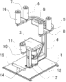
Shown in Figure of description 1 and accompanying drawing 2; Training aids is reversed in a kind of back; Comprise base 1 and be erected at the cushion 3 of base 1 top through pillar 2, hydraulic pressure oscillating cylinder 12 also is installed on the base 1, hydraulic pressure oscillating cylinder 12 is provided with the resistance control valve 13 of these swinging mounting 4 swing resistances of swinging mounting 4 and scalable; Hydraulic pressure oscillating cylinder 12 is positioned at the dead astern of pillar 2 and is installed on the base 1 that cushion 3 transfers, and hydraulic pressure oscillating cylinder 12 front portions also are fixedly connected with pillar 2 to guarantee its stability through connector; Swinging mounting 4 tops are equipped with " U " shape support 5; Be symmetrically arranged with two groups of shoulder arm stopping means on two straight-bars of " U " shape support 5 openings; Every group of stopping means comprises two shoulder arm limited posts 6 that are enclosed with neonychium 16; Define between two shoulder arm limited posts 6 width and common people's arm width similar put arm lattice 7, put arm lattice 7 bottoms and be provided with the cushion 8 that is used to protect arm; " U " shape mid-stent installed inside has back cushion 9.
Also be provided with foot's fixture on the base 1, comprise a montant 14 that tilts to pillar 2 directions and be arranged on the cross bar 15 on the said montant 14, montant 14 is positioned at the dead ahead of pillar 2.Pillar 2 tops are provided with crossbeam 10, and crossbeam 10 points to foot's positioner one end and is longer than cushion 3, and this length end is equipped with vertical shank limited post 11, and this shank limited post 11 is similar with the 26S Proteasome Structure and Function of shoulder arm limited post 6.
The user is sitting on the cushion during training; Upper arm placed in the arm lattice and take be placed on the cushion of putting arm lattice bottoms, the back tightly is resisted against on the back cushion, and shank is placed apart in shank limited post both sides; Step catches on the cross bar 15 of step stopping means, can begin the training that sways one's hips.Can realize the swaying one's hips reciprocating motion of training of the hydraulic pressure oscillating cylinder of cushion below is through regulating the pressure-regulating valve adjustment movement resistance on the hydraulic pressure oscillating cylinder.
Should be understood that this embodiment only to be used to the utility model is described and be not used in the restriction the utility model scope.Should be understood that in addition those skilled in the art can do various changes or modification to the utility model after the content of having read the utility model instruction, these equivalent form of values fall within the application's appended claims institute restricted portion equally.