CN202590950U - Ceramic slurry deironing device - Google Patents
Ceramic slurry deironing device Download PDFInfo
- Publication number
- CN202590950U CN202590950U CN 201220144736 CN201220144736U CN202590950U CN 202590950 U CN202590950 U CN 202590950U CN 201220144736 CN201220144736 CN 201220144736 CN 201220144736 U CN201220144736 U CN 201220144736U CN 202590950 U CN202590950 U CN 202590950U
- Authority
- CN
- China
- Prior art keywords
- deironing
- iron removal
- iron
- removal trough
- multistage
- Prior art date
- Legal status (The legal status is an assumption and is not a legal conclusion. Google has not performed a legal analysis and makes no representation as to the accuracy of the status listed.)
- Expired - Fee Related
Links
Images

Landscapes
- Crushing And Grinding (AREA)
Abstract
The utility model relates to a ceramic slurry deironing device, which comprises a ball mill, a stirring device and deironing grooves, wherein the deironing grooves are multistage deironing grooves and are sequentially connected with one another end to end; magnet bars which are perpendicular to a slurry flowing direction in rows are arranged at the bottom of each deironing groove; magnet bar fixing seats are arranged at two ends of each magnet bar; the stirring device comprises a first stirring barrel and a second stirring barrel; one end of the first stirring barrel is connected with the ball mill, and the other end of the first stirring barrel is connected with the multistage deironing grooves; and the last stage of deironing groove is sequentially connected with the second stirring barrel and a drying tower. The ceramic slurry deironing device is reasonable in design, and can remove iron tramp particles with different finenesses in ceramic slurry in a graded manner, the magnet bars are distributed uniformly, the slurry is wavy in a flowing process, deironing efficiency can be improved, deposition of iron tramp can be prevented by the stirring device, and a deironing effect is good.
Description
Technical field
The utility model relates to a kind of deironing apparatus, particularly relates to a kind of deironing apparatus of removing iron powder in the ceramic size.
Background technology
The deferrization process that is widely used at present in the ceramic abrasive industry mainly contains following several kinds: the stainless steel Permanent-magneto magnetic bar is adopted in (1); Method for removing iron is that the bar magnet with right quantity is positioned in the fixing conveyer trough; Pursue bar magnet the root taking-up and erase the irony that is adsorbed on the bar magnet surface with cloth clean being put in the stock tank more afterwards by manual work.Because the bar magnet quantity of using during general industry is produced is more, wash number is more frequent, and labour intensity is big, is prone to the production accident of bar magnet tong in the operating process.(2) adopt ferrite bead or square magnetic patch, deironing mode and bar magnet are similar, owing to magnetic a little less than, de-ferrous effect is relatively poor, only is used for the removal of general ferromagnetism particle irony.(3) adopt electromagnet, the deironing principle is in coil, to feed direct current, produces magnetic field, makes slurry flow through the sieve lattice plate of a magnetic conduction, and irony is attracted on the sieve lattice plate, cleans then.Though this method can alleviate operator's labour intensity to a certain extent, because the ferromagnetic journey of electromagnetism is shorter, need two-stage tandem to use sometimes, the unit cost is higher, and power consumption is bigger simultaneously, and input cost and maintenance cost are also higher.
Along with the fast development of China's industry and constantly pouring in of external product; Every profession and trade to ceramic cartridge require increasingly high; Especially electrovacuum ceramic tube envelope have high temperature resistant, corrosion-resistant, mechanical strength is high and characteristics such as Heat stability is good, is widely used in fields such as electric power, weaving, machinery, metallurgy and space flight navigation.Iron-holder in the electrovacuum ceramic tube envelope more needs strict requirement, and the iron tramp content overproof can have a strong impact on the qualification rate of product in the ceramic cartridge, therefore, is badly in need of wanting a cover can effectively remove the deironing apparatus of iron tramp in the ceramic size raw material.
The utility model content
The technical problem that the utility model will solve: to the deficiency that prior art exists, provide a kind of can hierarchical processing, the ceramic sizing material iron removing device of easy to operate, good iron removal effect.
The technical scheme of the utility model:
A kind of ceramic sizing material iron removing device; Comprise ball mill, agitating device and iron removal trough, said iron removal trough is multistage iron removal trough, and iron removal troughs at different levels are end to end successively; Every grade of iron removal trough bottom is provided with vertical bar magnet in a row with the slip flow direction, and the two ends of every bar magnet are provided with the bar magnet holder; Said agitating device comprises first agitator, second agitator, an end of first agitator ball mill of ining succession, and the other end and multistage iron removal trough join, and the afterbody iron removal trough links to each other with second agitator, drying tower successively.
Said multistage iron removal trough is three grades, sets gradually from high to low by the slip flow direction.The bottom was the inclination angle of 10-15 degree when multistage iron removal trough was provided with to mobile inclination of slip and horizontal direction; Described bar magnet is evenly distributed.
The positive beneficial effect of the utility model:
(1) this device is reasonable in design, and the iron tramp particulate of different fineness in the ceramic size is removed in the ability classification, and bar magnet is evenly distributed, and becomes wavy in the slurry flow process, can improve de-ironing efficiency, installs agitating device simultaneously additional, can prevent the iron tramp deposition, good iron removal effect.
(2) this apparatus structure is simple, and is easy to operate, can realize working continuously, and can effectively remove the iron tramp in the ceramic raw material, improves the inherence and the presentation quality of porcelain shell product, improves batch qualification rate that the porcelain shell is produced, and increases economic efficiency.
(3) the utility model can not only be used for the deironing of ceramic size, also can be applicable to the deironing of chemical industry slurries such as other abrasive materials.
Description of drawings
Fig. 1: the ceramic sizing material iron removing device sketch map of the utility model;
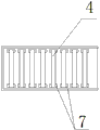
Fig. 2: the iron removal trough A of the utility model is to the plan structure sketch map.
Among the figure, 1 is ball mill, and 2 is first agitator, and 3 is iron removal trough, and 4 is bar magnet, and 5 is second agitator, and 6 is drying tower, and 7 is the bar magnet holder.
The specific embodiment
Embodiment 1: referring to Fig. 1, Fig. 2; A kind of ceramic sizing material iron removing device; Comprise ball mill 1, agitating device and iron removal trough 3, said iron removal trough 3 is multistage iron removal trough, and iron removal troughs at different levels are end to end successively; Every grade of iron removal trough bottom is provided with the bar magnet 4 vertical and in a row with the slip flow direction, and bar magnet evenly distributes in the iron removal trough bottom; The two ends of every bar magnet are provided with bar magnet holder 7;
Wherein agitating device comprises an end of first agitator 2, second agitator, 5, the first agitators 2 ball mill 1 of ining succession, and the other end and multistage iron removal trough join, and the afterbody iron removal trough links to each other with second agitator 5, drying tower 6 successively.Multistage iron removal trough is provided with three grades in this example, sets gradually from high to low by the slip flow direction.
Embodiment 2: identical with embodiment 1, difference is:
The bottom tilted to the slip flow direction when iron removal troughs at different levels were provided with, and every grade of iron removal trough and horizontal direction have the inclination angle of 10-15 degree.
Claims (4)
1. ceramic sizing material iron removing device; Comprise ball mill, agitating device and iron removal trough; It is characterized in that: said iron removal trough is multistage iron removal trough; Iron removal troughs at different levels are end to end successively, and every grade of iron removal trough bottom is provided with vertical bar magnet in a row with the slip flow direction, and the two ends of every bar magnet are provided with the bar magnet holder; Said agitating device comprises first agitator, second agitator, an end of first agitator ball mill of ining succession, and the other end and multistage iron removal trough join, and the afterbody iron removal trough links to each other with second agitator, drying tower successively.
2. ceramic sizing material iron removing device according to claim 1 is characterized in that: said multistage iron removal trough is three grades, sets gradually from high to low by the slip flow direction.
3. ceramic sizing material iron removing device according to claim 1 is characterized in that: the bottom was the inclination angle of 10-15 degree when multistage iron removal trough was provided with to mobile inclination of slip and horizontal direction.
4. ceramic sizing material iron removing device according to claim 1 is characterized in that: described bar magnet is evenly distributed.
Priority Applications (1)
| Application Number | Priority Date | Filing Date | Title |
|---|---|---|---|
| CN 201220144736 CN202590950U (en) | 2012-04-09 | 2012-04-09 | Ceramic slurry deironing device |
Applications Claiming Priority (1)
| Application Number | Priority Date | Filing Date | Title |
|---|---|---|---|
| CN 201220144736 CN202590950U (en) | 2012-04-09 | 2012-04-09 | Ceramic slurry deironing device |
Publications (1)
| Publication Number | Publication Date |
|---|---|
| CN202590950U true CN202590950U (en) | 2012-12-12 |
Family
ID=47308533
Family Applications (1)
| Application Number | Title | Priority Date | Filing Date |
|---|---|---|---|
| CN 201220144736 Expired - Fee Related CN202590950U (en) | 2012-04-09 | 2012-04-09 | Ceramic slurry deironing device |
Country Status (1)
| Country | Link |
|---|---|
| CN (1) | CN202590950U (en) |
Cited By (8)
| Publication number | Priority date | Publication date | Assignee | Title |
|---|---|---|---|---|
| CN104174487A (en) * | 2014-08-06 | 2014-12-03 | 禹州市盛火电器有限公司 | High-voltage electric ceramic sludge deironing and screening system |
| CN104525361A (en) * | 2014-12-01 | 2015-04-22 | 广东尚高科技有限公司 | Novel iron-removal apparatus |
| CN104835944A (en) * | 2015-04-23 | 2015-08-12 | 金川集团股份有限公司 | Method and device for lowering content of magnetic foreign bodies in cathode material for lithium ion cell |
| CN106694217A (en) * | 2017-03-20 | 2017-05-24 | 深圳市玖创科技有限公司 | Graphite multistage ladder-like iron remover |
| CN106733151A (en) * | 2016-12-09 | 2017-05-31 | 大连凯泓科技有限公司 | The staged primary purifying device of waste liquid is cut with iron for high concentration |
| CN107755086A (en) * | 2017-10-24 | 2018-03-06 | 广西联壮科技股份有限公司 | A kind of mud is snakelike to flow to Deironing mechanism |
| CN108176497A (en) * | 2017-12-27 | 2018-06-19 | 郑州赫恩电子信息技术有限公司 | A kind of multistage deironing filter |
| CN109865812A (en) * | 2019-03-29 | 2019-06-11 | 东北大学 | A kind of flow of metal purification pressure forming equipment |
-
2012
- 2012-04-09 CN CN 201220144736 patent/CN202590950U/en not_active Expired - Fee Related
Cited By (10)
| Publication number | Priority date | Publication date | Assignee | Title |
|---|---|---|---|---|
| CN104174487A (en) * | 2014-08-06 | 2014-12-03 | 禹州市盛火电器有限公司 | High-voltage electric ceramic sludge deironing and screening system |
| CN104525361A (en) * | 2014-12-01 | 2015-04-22 | 广东尚高科技有限公司 | Novel iron-removal apparatus |
| CN104835944A (en) * | 2015-04-23 | 2015-08-12 | 金川集团股份有限公司 | Method and device for lowering content of magnetic foreign bodies in cathode material for lithium ion cell |
| CN106733151A (en) * | 2016-12-09 | 2017-05-31 | 大连凯泓科技有限公司 | The staged primary purifying device of waste liquid is cut with iron for high concentration |
| CN106733151B (en) * | 2016-12-09 | 2018-02-27 | 大连凯泓科技有限公司 | The staged primary purifying device of waste liquid is cut with iron for high concentration |
| CN106694217A (en) * | 2017-03-20 | 2017-05-24 | 深圳市玖创科技有限公司 | Graphite multistage ladder-like iron remover |
| CN106694217B (en) * | 2017-03-20 | 2018-05-18 | 常州爱诺得新能源科技有限公司 | A kind of multistage stepped iron remover of graphite |
| CN107755086A (en) * | 2017-10-24 | 2018-03-06 | 广西联壮科技股份有限公司 | A kind of mud is snakelike to flow to Deironing mechanism |
| CN108176497A (en) * | 2017-12-27 | 2018-06-19 | 郑州赫恩电子信息技术有限公司 | A kind of multistage deironing filter |
| CN109865812A (en) * | 2019-03-29 | 2019-06-11 | 东北大学 | A kind of flow of metal purification pressure forming equipment |
Similar Documents
| Publication | Publication Date | Title |
|---|---|---|
| CN202590950U (en) | Ceramic slurry deironing device | |
| CN107051713B (en) | The method of purification of quartz sand | |
| CN102744145A (en) | Scrubbing process for diatomaceous earth ores | |
| CN204320637U (en) | A kind of cement slurry alternate grade roto-siofter | |
| CN201862465U (en) | Magnetic separator for quartz sand production by wet process | |
| CN103736587B (en) | Non-homogeneous strong magnetizing mediums, magnetic plant and magnetic selection method | |
| CN214864341U (en) | Wet preparation production line of high-purity quartz sand | |
| CN203355864U (en) | Ceramic slurry iron removal equipment | |
| CN205165196U (en) | Iron powder is choice device in grades | |
| CN102794229B (en) | Vertical stirring concentrator | |
| CN102626671B (en) | Magnetic field ore dressing method and ore dressing equipment | |
| CN205361588U (en) | Choice process units in quartzy ore deposit | |
| CN206810454U (en) | A kind of novel mineral crushing system | |
| CN102247932B (en) | Multi-force field spiral centrifugal permanent magnet high gradient magnet separator | |
| CN201791569U (en) | Dry mixing grinding machine | |
| CN205095931U (en) | Carborundum granule sorting unit | |
| CN209138869U (en) | A kind of automatic iron removing equipment | |
| CN104384014A (en) | Ceramic iron removal machine | |
| CN208357018U (en) | Quartz sand sorter | |
| WO2016187858A1 (en) | Method for sorting minerals | |
| CN203663999U (en) | Non-uniform strong magnetic medium and magnetic separation equipment | |
| CN205761759U (en) | Slurry filtering device | |
| CN203862384U (en) | Fluidized magnetic agglomeration gravity separation equipment | |
| CN204583459U (en) | Quartz sand sorter | |
| CN204294354U (en) | Sorting machine |
Legal Events
| Date | Code | Title | Description |
|---|---|---|---|
| C14 | Grant of patent or utility model | ||
| GR01 | Patent grant | ||
| C17 | Cessation of patent right | ||
| CF01 | Termination of patent right due to non-payment of annual fee |
Granted publication date: 20121212 Termination date: 20140409 |