CN202558420U - Elevator - Google Patents

Elevator Download PDF

Info

Publication number
CN202558420U
CN202558420U CN2012201889870U CN201220188987U CN202558420U CN 202558420 U CN202558420 U CN 202558420U CN 2012201889870 U CN2012201889870 U CN 2012201889870U CN 201220188987 U CN201220188987 U CN 201220188987U CN 202558420 U CN202558420 U CN 202558420U
Authority
CN
China
Prior art keywords
guide rail
wheel
elevator
tensioning wheel
tension wheel
Prior art date
Legal status (The legal status is an assumption and is not a legal conclusion. Google has not performed a legal analysis and makes no representation as to the accuracy of the status listed.)
Expired - Lifetime
Application number
CN2012201889870U
Other languages
Chinese (zh)
Inventor
周芳
彭建国
Current Assignee (The listed assignees may be inaccurate. Google has not performed a legal analysis and makes no representation or warranty as to the accuracy of the list.)
HUNAN SHIYOU ELECTRIC PUBLIC Co Ltd
Original Assignee
Xiangtan Shitong Electrical Co Ltd
Priority date (The priority date is an assumption and is not a legal conclusion. Google has not performed a legal analysis and makes no representation as to the accuracy of the date listed.)
Filing date
Publication date
Application filed by Xiangtan Shitong Electrical Co Ltd filed Critical Xiangtan Shitong Electrical Co Ltd
Priority to CN2012201889870U priority Critical patent/CN202558420U/en
Application granted granted Critical
Publication of CN202558420U publication Critical patent/CN202558420U/en
Anticipated expiration legal-status Critical
Expired - Lifetime legal-status Critical Current

Links

Images

Abstract

The utility model discloses an elevator which comprises an elevator body and a guide rail. A first tensioning wheel, a second tensioning wheel, a reduction gear box and a falling protector are arranged on the elevator body, a first adjustable bolt and a second adjustable bolt are respectively arranged on the first tensioning wheel and the second tensioning wheel, and the first tensioning wheel is arranged below the second tensioning wheel. A first chain wheel is arranged at the output end of the reduction gear box, and a second chain wheel is arranged at the output end of the falling protector. The guide rail comprises a guide rail basic body and a plurality of pin shafts, the plurality of pin shafts are arranged on the guide rail basic body along the guide rail direction, centers of the pin shafts are located in one straight line, spaces between the pin shafts are same, and the spaces correspond to pitches of the first chain wheel and the second chain wheel. The first chain wheel and the second chain wheel are respectively meshed with the pin shafts on the guide rail, and lateral faces of the guide rail are closely pressed by the first tensioning wheel and the second tensioning wheel respectively. The elevator has the advantages of being simple in manufacture, low in installation accuracy requirement, low in manufacture cost and stable and reliable in operation.

Description

A kind of elevator
Technical field
The utility model relates to a kind of bont, more particularly relates to a kind of elevator.
Background technology
Existing elevator mainly promotes hanging basket through steel rope or rack-and-gear guide rail.The elevator of steel wire rope type, because the flexibility of steel rope, its hanging basket in operational process is prone to shake, and moves not steady; And the pinion and-rack elevator, though operate steadily, the cost of tooth bar is high, and setting accuracy requires high.
The utility model content
To the defective of prior art, in order to improve the elevator traveling comfort, it is simple to make it have production and processing concurrently, the characteristics that cost is low, and the utility model provides a kind of later-model elevator.
The utility model realizes that the technical scheme that above-mentioned purpose adopts is: comprise elevator body and guide rail; The elevator body is provided with first tension wheel, second tension wheel, reducing gearbox and falling protector, and first tension wheel and second tension wheel are respectively equipped with first adjustable bolt and second adjustable bolt, and first tension wheel places the below of second tension wheel; The reducing gearbox mouth is provided with first sprocket wheel, and the mouth of falling protector is provided with second sprocket wheel; Said guide rail comprises guide rail matrix and a plurality of bearing pin, and the guide rail matrix is provided with a plurality of bearing pins along the guide rail direction, being centered close on the straight line of bearing pin, and spacing is identical between the bearing pin, and corresponding with the pitch of first sprocket wheel, second sprocket wheel; First sprocket wheel, second sprocket wheel respectively with guide rail on bearing pin engagement, first tension wheel and second tension wheel compress respectively on the side of guide rail.
Compared with prior art, the beneficial effect of the utility model is: the utility model production and processing is simple, and setting accuracy requires low, and cost of manufacture is low; The utility model adopts the bearing pin engaged transmission on sprocket wheel and the guide rail, and it is reliable to operate steadily.
Description of drawings
Fig. 1 is that the axle that waits of the utility model is surveyed view.
Fig. 2 is the front view of the utility model.
Fig. 3 is the left view of the utility model.
Fig. 4 is the guide rail structure scheme drawing of the utility model.
The specific embodiment
Below in conjunction with accompanying drawing and embodiment the utility model is further described.
With reference to accompanying drawing, the utility model comprises elevator body 3 and guide rail 10; Elevator body 3 is provided with first tension wheel 5, second tension wheel 9, reducing gearbox 13 and falling protector 14; First tension wheel 5 and second tension wheel 9 are respectively equipped with the below that first adjustable bolt 4 and second adjustable bolt, 2, the first tension wheels 5 place second tension wheel 9; Reducing gearbox 13 mouths are provided with first sprocket wheel 7, and the mouth of falling protector 14 is provided with second sprocket wheel 8; Said guide rail 10 comprises guide rail matrix 15 and a plurality of bearing pins 11; Guide rail matrix 15 is provided with a plurality of bearing pins 11 along guide rail 10 directions, being centered close on the straight line of bearing pin 11, and spacing is identical between the bearing pin 11, and corresponding with the pitch of first sprocket wheel 7, second sprocket wheel 8; First sprocket wheel 7, second sprocket wheel 8 respectively with guide rail on bearing pin 11 engagements, first tension wheel 5 and second tension wheel 9 compress respectively on the side of guide rail 10.
In the working process; Stand on people's platform 1 people from station or put goods provides power through drive motor 12, and first sprocket wheel 7 that drives through reducing gearbox 13 rotates; Bearing pin 11 engagements on first sprocket wheel 7 and the guide rail 10 make elevator body 3 move up and down along guide rail 10.When breaking down, when elevator body 3 fell downwards, falling protector 14 actions made that elevator body 3 is out of service, the safety of assurance personnel and goods.

Claims (1)

1. an elevator is characterized in that: comprise elevator body and guide rail; The elevator body is provided with first tension wheel, second tension wheel, reducing gearbox and falling protector, and first tension wheel and second tension wheel are respectively equipped with first adjustable bolt and second adjustable bolt, and first tension wheel places the below of second tension wheel; The reducing gearbox mouth is provided with first sprocket wheel, and the mouth of falling protector is provided with second sprocket wheel; Said guide rail comprises guide rail matrix and a plurality of bearing pin, and the guide rail matrix is provided with a plurality of bearing pins along the guide rail direction, being centered close on the straight line of bearing pin, and spacing is identical between the bearing pin, and corresponding with the pitch of first sprocket wheel, second sprocket wheel; First sprocket wheel, second sprocket wheel respectively with guide rail on bearing pin engagement, first tension wheel and second tension wheel compress respectively on the side of guide rail.
CN2012201889870U 2012-04-28 2012-04-28 Elevator Expired - Lifetime CN202558420U (en)

Priority Applications (1)

Application Number Priority Date Filing Date Title
CN2012201889870U CN202558420U (en) 2012-04-28 2012-04-28 Elevator

Applications Claiming Priority (1)

Application Number Priority Date Filing Date Title
CN2012201889870U CN202558420U (en) 2012-04-28 2012-04-28 Elevator

Publications (1)

Publication Number Publication Date
CN202558420U true CN202558420U (en) 2012-11-28

Family

ID=47208103

Family Applications (1)

Application Number Title Priority Date Filing Date
CN2012201889870U Expired - Lifetime CN202558420U (en) 2012-04-28 2012-04-28 Elevator

Country Status (1)

Country Link
CN (1) CN202558420U (en)

Cited By (2)

* Cited by examiner, † Cited by third party
Publication number Priority date Publication date Assignee Title
CN104773632A (en) * 2015-04-21 2015-07-15 高爱峰 Miniature elevator mounted on vertical ladder
CN109761133A (en) * 2019-03-26 2019-05-17 济南工程职业技术学院 A kind of knapsack type elevator

Similar Documents

Publication Publication Date Title
CN202361807U (en) Charging lifting machine for electric furnace
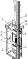
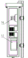
CN202558420U (en) Elevator
CN202390133U (en) Portable cutter mill
CN107934402A (en) With upper and lower traction belts machine
CN202850544U (en) Gear -rack transmission pit type stereo garage
CN204457014U (en) The lifting drive apparatus of lift-sliding machinery garage
CN202690943U (en) Driving device for woodworking band sawing machine carriage
CN201932801U (en) Escalator
CN101886537A (en) Tractor tower type pumping unit device
CN202575533U (en) Wire take-up device
CN201371173Y (en) Chain transmission mechanism of aluminum section traction engine
CN206068694U (en) A kind of wheel hub linear conveying device
CN202337642U (en) Traveling part device of gantry crane for railway
CN203473738U (en) Novel double-extrusion mechanism
CN203048466U (en) Mine low-speed prop pulling hoist
CN101708810B (en) Mechanical double-speed superimposed type rapid telescopic arm frame
CN203602251U (en) Travelling crane device for workshop
CN201832925U (en) Transmission mechanism of steel bar straightening machine
CN202642704U (en) Wheel type chain grate bearing guide mechanism
CN205089926U (en) Transmission device
CN201278679Y (en) High clearance gear box of cutter rower
CN203998649U (en) A kind of modular power cucurbit
CN202715599U (en) Chain-driven cleaning machine
CN204727384U (en) A kind of transmission device of rail mounted elevator
CN204755813U (en) Embosser main drive system

Legal Events

Date Code Title Description
C14 Grant of patent or utility model
GR01 Patent grant
ASS Succession or assignment of patent right

Owner name: HUNAN SHIYOU ELECTRIC CO., LTD.

Free format text: FORMER OWNER: XIANGTAN SHITONG ELECTRICAL CO. LTD.

Effective date: 20140421

C41 Transfer of patent application or patent right or utility model
COR Change of bibliographic data

Free format text: CORRECT: ADDRESS; FROM: 411133 XIANGTAN, HUNAN PROVINCE TO: 411104 XIANGTAN, HUNAN PROVINCE

TR01 Transfer of patent right

Effective date of registration: 20140421

Address after: 411104 Torch Innovation and Pioneer Park, hi tech Zone, Hunan, Xiangtan

Patentee after: HUNAN SHIYOU ELECTRIC PUBLIC CO., LTD.

Address before: 411133 No. 8 Chutian Road, twin Horse Industrial Park, Hunan, Xiangtan, China

Patentee before: Xiangtan Shitong Electrical Co., Ltd.

CX01 Expiry of patent term

Granted publication date: 20121128