CN202522482U - Extensometer for measuring yield strength of plate-shaped tensile test sample of pipeline steel - Google Patents
Extensometer for measuring yield strength of plate-shaped tensile test sample of pipeline steel Download PDFInfo
- Publication number
- CN202522482U CN202522482U CN201220184913XU CN201220184913U CN202522482U CN 202522482 U CN202522482 U CN 202522482U CN 201220184913X U CN201220184913X U CN 201220184913XU CN 201220184913 U CN201220184913 U CN 201220184913U CN 202522482 U CN202522482 U CN 202522482U
- Authority
- CN
- China
- Prior art keywords
- rod
- extensometer
- yield strength
- shaped
- pipeline steel
- Prior art date
- Legal status (The legal status is an assumption and is not a legal conclusion. Google has not performed a legal analysis and makes no representation as to the accuracy of the status listed.)
- Expired - Fee Related
Links
- 229910000831 Steel Inorganic materials 0.000 title claims abstract description 32
- 239000010959 steel Substances 0.000 title claims abstract description 32
- 238000009864 tensile test Methods 0.000 title description 3
- 238000005259 measurement Methods 0.000 claims abstract description 8
- 239000002184 metal Substances 0.000 claims description 8
- 238000012360 testing method Methods 0.000 description 20
- 230000002146 bilateral effect Effects 0.000 description 9
- 238000000034 method Methods 0.000 description 8
- 238000006243 chemical reaction Methods 0.000 description 3
- 238000010586 diagram Methods 0.000 description 3
- 239000000463 material Substances 0.000 description 3
- 230000009286 beneficial effect Effects 0.000 description 2
- 230000005540 biological transmission Effects 0.000 description 2
- 239000013013 elastic material Substances 0.000 description 2
- TZCXTZWJZNENPQ-UHFFFAOYSA-L barium sulfate Chemical compound [Ba+2].[O-]S([O-])(=O)=O TZCXTZWJZNENPQ-UHFFFAOYSA-L 0.000 description 1
- 238000005452 bending Methods 0.000 description 1
- 238000013461 design Methods 0.000 description 1
- 238000004643 material aging Methods 0.000 description 1
- 238000012986 modification Methods 0.000 description 1
- 230000004048 modification Effects 0.000 description 1
- 238000012545 processing Methods 0.000 description 1
- 238000005070 sampling Methods 0.000 description 1
- 238000004904 shortening Methods 0.000 description 1
- 230000003746 surface roughness Effects 0.000 description 1
- 238000004154 testing of material Methods 0.000 description 1
Images


Classifications
-
- Y—GENERAL TAGGING OF NEW TECHNOLOGICAL DEVELOPMENTS; GENERAL TAGGING OF CROSS-SECTIONAL TECHNOLOGIES SPANNING OVER SEVERAL SECTIONS OF THE IPC; TECHNICAL SUBJECTS COVERED BY FORMER USPC CROSS-REFERENCE ART COLLECTIONS [XRACs] AND DIGESTS
- Y02—TECHNOLOGIES OR APPLICATIONS FOR MITIGATION OR ADAPTATION AGAINST CLIMATE CHANGE
- Y02E—REDUCTION OF GREENHOUSE GAS [GHG] EMISSIONS, RELATED TO ENERGY GENERATION, TRANSMISSION OR DISTRIBUTION
- Y02E30/00—Energy generation of nuclear origin
- Y02E30/30—Nuclear fission reactors
Landscapes
- Investigating Strength Of Materials By Application Of Mechanical Stress (AREA)
Abstract
一种用于管线钢板状拉伸试样屈服强度测量的引伸计,包括上夹具、下夹具、连接杆、紧固件和距离测量装置,上夹具包括上壁和侧壁,上壁和侧壁在相互的连接端相互固定设置,连接杆的一端固定在上壁的自由端并且垂直于上壁,连接杆的另一端铰接在下夹具的一端,下夹具的另一端设置有基准面;紧固件包括至少一组,每组紧固件包括设置在上壁上的上紧固件和设置在下夹具上的下紧固件,当连接杆垂直于下夹具时,每组内的上紧固件和下紧固件之间的联系平行于连接杆。本实用新型可减少因试样偏心或者是引伸计打滑现象对管线钢屈服强度测量结果带来的误差,从而得出可靠的管线钢屈服强度值。
An extensometer for measuring the yield strength of pipeline steel plate-like tensile specimens, including upper clamps, lower clamps, connecting rods, fasteners and distance measuring devices, the upper clamps include upper walls and side walls, upper walls and side walls The mutual connection ends are fixed to each other, one end of the connecting rod is fixed on the free end of the upper wall and is perpendicular to the upper wall, the other end of the connecting rod is hinged on one end of the lower clamp, and the other end of the lower clamp is provided with a datum surface; fasteners Including at least one group, each group of fasteners includes upper fasteners arranged on the upper wall and lower fasteners arranged on the lower fixture, when the connecting rod is perpendicular to the lower fixture, the upper fasteners and the lower fasteners in each group The link between the lower fasteners is parallel to the connecting rod. The utility model can reduce the error caused by the eccentricity of the sample or the slippage of the extensometer to the measurement result of the yield strength of the pipeline steel, thereby obtaining a reliable value of the yield strength of the pipeline steel.
Description
技术领域 technical field
本实用新型涉及管线钢材料试验技术领域,尤其涉及一种用于管线钢板状拉伸试样屈服强度测量的引伸计。The utility model relates to the technical field of pipeline steel material testing, in particular to an extensometer for measuring the yield strength of pipeline steel plate-like tensile samples.
背景技术 Background technique
管线钢材料的屈服强度(如Rt0.5)是表征管线钢力学性能最重要的指标之一。管线钢屈服强度的测试影响因素很多,包括加载速度、取样方向、试样形式、试样加工精度、材料时效、试样夹持方式、实验加载控制方式、屈服点选取、试验设备等。因此,为了得到可靠的试验测试结果,需要有效地减少各种不利因素的影响。对于一台特定的试验机而言,试验设备能力为客观影响因素,无法进行人为克服,而对于其他的影响因素,可以通过人为努力进行克服,从而得到良好的测试结果。The yield strength (such as Rt0.5) of pipeline steel material is one of the most important indicators to characterize the mechanical properties of pipeline steel. There are many factors affecting the yield strength test of pipeline steel, including loading speed, sampling direction, sample form, sample processing accuracy, material aging, sample clamping method, experimental loading control method, yield point selection, test equipment, etc. Therefore, in order to obtain reliable experimental test results, it is necessary to effectively reduce the influence of various unfavorable factors. For a specific testing machine, the ability of the testing equipment is an objective influencing factor that cannot be overcome artificially, while other influencing factors can be overcome through human efforts to obtain good test results.
拉伸试样的夹持方式有单边夹持和双边夹持,不同的夹持方式对试验结果会产生一定的影响。传统的单边夹持引伸计一般采用橡皮筋或其他带弹性的材料将引伸计固定于试样上,引伸计以单侧刀口的形式与试样呈单边线性接触;传统的双边夹持引伸计则以双侧刀口的形式与试样呈双边线性接触。采用单边夹持引伸计时,一方面,引伸计的刀口可与试样表面形成相对较好的线性咬合紧固,而对引伸计起固定作用的橡皮筋或其他带弹性的材料与试样接触时呈面积型紧固,因此,可能在试验的过程中产生打滑现象;另一方面,单边夹持引伸计测量的是试样表面一侧的伸长,由于试验时拉伸试样不可避免地存在偏心拉伸的情况,试样一侧的伸长包含了因偏心产生的弯曲变形而导致的伸长或缩短,因此,试验的结果会不稳定,并产生比较大的误差。采用双边夹持引伸计时,由于能够测量试样双侧变形的平均值,不受试样偏心拉伸的影响,往往能测得相对较好的屈服强度结果,因此,对于要求较高的海底管线用管,通常要求采用双边夹持引伸计进行屈服强度测试,如2007版DNV-OS-F101(SUBMARINEPIPELINE SYSTEMS)中明确规定,在管线钢管母材屈服强度测试过程中,必须使用双边夹持引伸计。There are unilateral clamping and bilateral clamping methods for tensile specimens, and different clamping methods will have a certain impact on the test results. The traditional single-sided clamping extensometer generally uses rubber bands or other elastic materials to fix the extensometer on the sample, and the extensometer is in unilateral linear contact with the sample in the form of a single-sided knife edge; the traditional double-sided clamping extensometer The gauge is in bilateral linear contact with the sample in the form of a double-sided knife edge. Using a single-side clamping extensometer, on the one hand, the knife edge of the extensometer can form a relatively good linear bite fastening with the surface of the sample, and the rubber band or other elastic material that fixes the extensometer is in contact with the sample Therefore, slippage may occur during the test; on the other hand, the unilateral clamping extensometer measures the elongation of one side of the sample surface, and it is inevitable to stretch the sample during the test. In the case of eccentric stretching, the elongation of one side of the sample includes the elongation or shortening caused by the bending deformation caused by eccentricity. Therefore, the test results will be unstable and cause relatively large errors. Using the bilateral clamp extensometer, because it can measure the average value of the deformation on both sides of the sample, and is not affected by the eccentric stretching of the sample, it can often measure relatively good yield strength results. Therefore, for submarine pipelines with high requirements For pipes, it is usually required to use bilateral clamping extensometers for yield strength testing. As clearly stipulated in the 2007 edition of DNV-OS-F101 (SUBMARINE PIPELINE SYSTEMS), in the process of yield strength testing of pipeline steel base materials, bilateral clamping extensometers must be used .
传统的、以刀口的形式与拉伸试样表面呈双边线性接触的双边夹持引伸计,由于受刀口锋利程度以及试样表面粗糙度等方面的影响,也可能会在试验过程中产生引伸计打滑现象,从而影响试验结果。The traditional bilateral clamping extensometer, which is in bilateral linear contact with the surface of the tensile sample in the form of a knife edge, may also produce extensometer damage during the test due to the influence of the sharpness of the knife edge and the surface roughness of the sample. Slip phenomenon, thus affecting the test results.
实用新型内容Utility model content
本实用新型的目的在于设计一种新型的用于管线钢板状拉伸试样屈服强度测量的引伸计,解决上述问题。The purpose of this utility model is to design a new type of extensometer for measuring the yield strength of pipeline steel plate-like tensile specimens, so as to solve the above-mentioned problems.
为了实现上述目的,本实用新型采用的技术方案如下:In order to achieve the above object, the technical scheme adopted by the utility model is as follows:
一种用于管线钢板状拉伸试样屈服强度测量的引伸计,包括上夹具、下夹具、连接杆、紧固件和距离测量装置,所述上夹具包括上壁和侧壁,所述上壁和所述侧壁在相互的连接端相互固定设置,所述连接杆的一端固定在所述上壁的自由端并且垂直于所述上壁,所述连接杆的另一端铰接在所述下夹具的一端,所述下夹具的另一端设置有基准面;An extensometer for measuring the yield strength of pipeline steel plate-shaped tensile specimens, comprising an upper clamp, a lower clamp, a connecting rod, a fastener and a distance measuring device, the upper clamp includes an upper wall and a side wall, and the upper The wall and the side wall are fixed to each other at the connecting ends, one end of the connecting rod is fixed on the free end of the upper wall and is perpendicular to the upper wall, and the other end of the connecting rod is hinged on the lower wall. One end of the clamp, the other end of the lower clamp is provided with a reference plane;
所述侧壁的自由端上设置有棒状杆,所述棒状杆的外缘面包括平面和圆弧面两部分,所述棒状杆可转动的设置在所述侧壁内并且垂直于所述连接杆,所述棒状杆距离所述上壁最远的所述圆弧面上到所述上壁的距离等于所述连接杆的长度;A rod-shaped rod is provided on the free end of the side wall, and the outer edge surface of the rod-shaped rod includes two parts of a plane and an arc surface, and the rod-shaped rod is rotatably arranged in the side wall and is perpendicular to the connection Rod, the distance from the arc surface of the rod-shaped rod farthest from the upper wall to the upper wall is equal to the length of the connecting rod;
所述距离测量装置设置在所述上夹具上并且其测量方向对准所述基准面;The distance measuring device is arranged on the upper fixture and its measuring direction is aligned with the reference plane;
所述紧固件包括至少一组,每组所述紧固件包括设置在所述上壁上的上紧固件和设置在所述下夹具上的下紧固件,当所述连接杆垂直于所述下夹具时,每组内的所述上紧固件和所述下紧固件之间的联系平行于所述连接杆。The fasteners include at least one group, and each group of fasteners includes an upper fastener arranged on the upper wall and a lower fastener arranged on the lower clamp, when the connecting rod is vertical The connection between the upper fastener and the lower fastener within each set is parallel to the connecting rod when the lower clamp is in place.
所述距离测量装置为千分尺,所述千分尺的量杆的自由端对准所述基准面。The distance measuring device is a micrometer, and the free end of the measuring rod of the micrometer is aligned with the reference plane.
所述上壁和所述侧壁相互垂直。The upper wall and the side walls are perpendicular to each other.
所述上壁和所述侧壁一体化成型而成。The upper wall and the side wall are integrally formed.
所述棒状杆为棒状金属杆。The rod-shaped rod is a rod-shaped metal rod.
还包括连接弹簧,所述连接弹簧的一端连接在所述上壁上,另一端连接在所述下夹具上。A connection spring is also included, one end of the connection spring is connected to the upper wall, and the other end is connected to the lower clamp.
所述棒状杆上还设置有棒状杆转动杆。The rod-shaped rod is also provided with a rod-shaped rod rotating rod.
至少一组所述紧固件设置在所述连接杆与所述基准面上的测量点之间的中部位置。At least one set of said fasteners is arranged at a middle position between said connecting rod and a measuring point on said datum surface.
所述紧固件为紧固螺丝。The fasteners are fastening screws.
管线钢管拉伸试样的方式有板状试样、棒状试样和胀环试样三种,在管线钢管实际生产过程中,一般对于X80级以下的管线钢管拉伸试验,都选用板状试样。本实用新型的目的就是为了精确测量管线钢板状拉伸试样的屈服强度,可减少因试样偏心或者是引伸计打滑现象对管线钢屈服强度测量结果带来的误差,能可靠地测量出管线钢屈服强度值。There are three types of tensile test methods for pipeline steel pipes: plate test specimens, bar test specimens and expansion ring test specimens. Sample. The purpose of this utility model is to accurately measure the yield strength of the pipeline steel plate-shaped tensile sample, which can reduce the error caused by the eccentricity of the sample or the slippage of the extensometer to the measurement result of the pipeline steel yield strength, and can reliably measure the yield strength of the pipeline steel. Steel yield strength value.
本实用新型的有益效果可以总结如下:The beneficial effects of the utility model can be summarized as follows:
1,本实用新型可减少因试样偏心或者是引伸计打滑现象对管线钢屈服强度测量结果带来的误差,从而得出可靠的管线钢屈服强度值。1. The utility model can reduce the error caused by the eccentricity of the sample or the slippage of the extensometer to the measurement result of the yield strength of the pipeline steel, so as to obtain a reliable value of the yield strength of the pipeline steel.
2,本实用新型属于双边夹持型引伸计,可以减少因拉伸试样偏心导致的测量误差;相对于传统的双边夹持引伸计,夹持时与试样表面呈点状接触,因此,受试验表面粗糙度及刀口锋利程度的影响小,夹持稳定,试验过程不打滑,减少了测量结果误差;2. The utility model belongs to the bilateral clamping extensometer, which can reduce the measurement error caused by the eccentricity of the tensile sample; compared with the traditional bilateral clamping extensometer, it is in point contact with the surface of the sample when clamping. Therefore, It is less affected by the roughness of the test surface and the sharpness of the knife edge, the clamping is stable, the test process does not slip, and the error of the measurement result is reduced;
3,本实用新型易于操作,夹持方便。3. The utility model is easy to operate and convenient to clamp.
附图说明 Description of drawings
图1为夹持了板状试样的本实用新型示意图;Fig. 1 is the utility model schematic diagram of clamping plate sample;
图2为本实用新型的俯视结构示意图;Fig. 2 is the top view structural representation of the utility model;
图3为本实用新型的主视结构示意图;Fig. 3 is the front view structure schematic diagram of the utility model;
图4为本实用新型的侧视结构示意图;Fig. 4 is the side view structural representation of the utility model;
图5为本实用新型的定位销结构示意图。Fig. 5 is a structural schematic diagram of the positioning pin of the present invention.
具体实施方式 Detailed ways
为了使本实用新型所解决的技术问题、技术方案及有益效果更加清楚明白,以下结合附图及实施例,对本实用新型进行进一步详细说明。应当理解,此处所描述的具体实施例仅仅用以解释本实用新型,并不用于限定本实用新型。In order to make the technical problems, technical solutions and beneficial effects solved by the utility model clearer, the utility model will be further described in detail below in conjunction with the accompanying drawings and embodiments. It should be understood that the specific embodiments described here are only used to explain the utility model, and are not intended to limit the utility model.
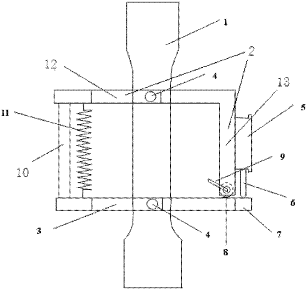
如图1至图5所示的一种用于管线钢板状拉伸试样屈服强度测量的引伸计,包括上夹具2、下夹具3、连接杆10、紧固件4和距离测量装置5,所述上夹具2包括上壁12和侧壁13,所述上壁12和所述侧壁13在相互的连接端相互固定设置,所述连接杆10的一端固定在所述上壁12的自由端并且垂直于所述上壁12,所述连接杆10的另一端铰接在所述下夹具3的一端,所述下夹具3的另一端设置有基准面7;所述侧壁13的自由端上设置有棒状杆8,所述棒状杆8的外缘面包括平面和圆弧面两部分,所述棒状杆8可转动的设置在所述侧壁13内并且垂直于所述连接杆10,所述棒状杆8距离所述上壁12最远的所述圆弧面上到所述上壁12的距离等于所述连接杆10的长度;所述距离测量装置5设置在所述上夹具2上并且其测量方向对准所述基准面7;所述紧固件4包括至少一组,每组所述紧固件4包括设置在所述上壁12上的上紧固件4和设置在所述下夹具3上的下紧固件4,当所述连接杆10垂直于所述下夹具3时,每组内的所述上紧固件4和所述下紧固件4之间的联系平行于所述连接杆10;所述距离测量装置5为千分尺,所述千分尺的量杆6的自由端对准所述基准面7;所述上壁12和所述侧壁13相互垂直;所述上壁12和所述侧壁13一体化成型而成;所述棒状杆8为棒状金属杆;所述紧固件4为紧固螺丝。在更加优选的实施例中,所述用于管线钢板状拉伸试样屈服强度测量的引伸计还包括连接弹簧11,所述连接弹簧11的一端连接在所述上壁12上,另一端连接在所述下夹具3上;所述棒状杆8上还设置有棒状杆8转动杆9;至少一组所述紧固件4设置在所述连接杆10与所述基准面7上的测量点之间的中部位置。An extensometer for measuring the yield strength of pipeline steel plate-shaped tensile specimens as shown in Figures 1 to 5, including an upper clamp 2, a lower clamp 3, a connecting
具体分析:Specific analysis:
本实用新型所涉及的引伸计主要由三部分组成:感受变形部分、传递部分和指示部分。夹有试样1的引伸计结构如图1所示,引伸计的俯视图、主视图和侧视图分别如图2、3、4所示。The extensometer involved in the utility model is mainly composed of three parts: a sensing deformation part, a transmitting part and an indicating part. The structure of the extensometer clamped with sample 1 is shown in Figure 1, and the top view, front view and side view of the extensometer are shown in Figures 2, 3 and 4, respectively.
(1)感受变形部分(1) feel the deformation part
主要由对上、下夹具以及上、下夹具中部的4个拉伸试样紧固螺丝组成,上夹具2呈角钢型结构,下夹具3呈平面结构,试样的紧固螺丝直接与试样1接触。上、下夹具间通过连接杆10和连接弹簧11相连接,其中连接杆10与上夹具2间呈固定链接,不能自由活动,与下夹具3呈铰链式连接,因此,在不紧固试样1时,下夹具3可通过与连接杆10的铰链式连接点相对上夹具2在连接弹簧11的作用范围内自由转动。下夹具3远离连接杆10的一端有一个基准平台,作为与千分尺量杆6尖端接触的基准面7。对于同一种壁厚的试样1,上、下夹具各有一个位于同侧的螺丝是固定的,上、下夹具各自的另外一个紧固螺丝用于调节,以紧固住拉伸试样1,同时以使上、下夹具在试验过程中感受变形。紧固螺丝具有较高的硬度和耐磨性,并且与试样1表面呈点状接触。It is mainly composed of the upper and lower fixtures and the four fastening screws for the tensile sample in the middle of the upper and lower fixtures. The upper fixture 2 has an angle steel structure, and the lower fixture 3 has a planar structure. The fastening screws of the sample are directly connected to the sample. 1 contact. The upper and lower clamps are connected by a connecting
(2)传递部分(2) Transmission part
引伸计定位销结构如图5所示,定位插销的结构包括一个转动杆9以及一根带有圆弧面和平面两部分的棒状金属杆,定位销的棒状金属杆位于上夹具2与下夹具3垂直一侧的平面内,并可沿壁厚中心自由转动,如图1中8所示,棒状金属杆的中心线与下夹具3平行。夹持时,旋转定位销的转动杆9,使得定位销棒状金属杆的圆弧面与下夹具3相接触,此时,下夹具3和上夹具2的一个平面正好平行,上、下夹具的紧固螺丝间的距离正好等于试样1的标距,也即是等于连接杆10的长度,旋紧上、下夹具的紧固螺丝,将引伸计固定于拉伸试样1上,然后再旋动定位销的转动杆9,使得定位销棒状金属杆的平面部分与下夹具3相对,则此时上夹具2与下夹具3垂直一侧的平面与下夹具3间不再接触,即可开始进行试验。此时,下夹具3的基准平台也已压迫到千分表的量杆6,使得千分表有一定读数。The structure of the positioning pin of the extensometer is shown in Figure 5. The structure of the positioning pin includes a
紧固螺丝在上、下夹具的位置正好处于上、下夹具的连接杆10与千分表量杆6之间的中部位置,这样,当上、下夹具的紧固螺丝之间的距离发生变化时,上、下夹具则以连接杆10与下夹具3链接处的铰链点为支点,其相对位置呈扇形状张开,根据杠杆原理,上、下夹具的紧固螺丝间张开的距离与千分表测得的量杆6相对于下夹具3基准面7张开的距离比例为1∶2。The position of the fastening screw on the upper and lower clamps is exactly in the middle position between the connecting
引伸计工作时,传递部分的任务就是将试样标距范围内的变形量传递到指示部分,并在该部分反应出来。When the extensometer is working, the task of the transmission part is to transmit the deformation within the gauge length range of the sample to the indication part, and reflect it in this part.
(3)指示部分(3) Instructions
引伸计的指示部分可以是一个千分表(分度值为0.001mm),试验开始后通过千分表量杆6测得的与基准面7间距离的变化,通过比例换算,直接读出试样标距范围内的应变量。The indication part of the extensometer can be a dial gauge (graduation value is 0.001mm), after the test starts, the change of the distance from the reference plane 7 measured by the
引伸计指示部分也可以通过电子信号转换装置(通过与下夹具3基准平台接触的量杆6使弹性元件产生应变,应变片将其转化为电阻变化量,再用适当的测量放大电路转化为电压信号,从而传到与之相连接的计算机上),从与电于信号转换装置相连的计算机上直接读出应变量。The extensometer indication part can also use the electronic signal conversion device (through the measuring
管线钢拉伸试验一般采用50mm的定标距试样1,当材料的规定总延伸率为0.5%(即应力-应变曲线上Rt0.5处对应的应变值)时,其标距内的变形量为0.025mm,则此时千分表上读数变化(或者弹性元件变形量)为0.05mm。The tensile test of pipeline steel generally adopts sample 1 with a calibration distance of 50mm. When the specified total elongation of the material is 0.5% (that is, the strain value corresponding to Rt 0.5 on the stress-strain curve), the deformation within the gauge length is 0.025mm, then the reading change on the dial indicator (or the deformation of the elastic element) is 0.05mm.
以上通过具体的和优选的实施例详细的描述了本实用新型,但本领域技术人员应该明白,本实用新型并不局限于以上所述实施例,凡在本实用新型的精神和原则之内,所作的任何修改、等同替换等,均应包含在本实用新型的保护范围之内。The utility model has been described in detail through specific and preferred embodiments above, but those skilled in the art should understand that the utility model is not limited to the above-described embodiments, and within the spirit and principles of the utility model, Any modifications, equivalent replacements, etc. should be included in the scope of protection of the present utility model.
Claims (9)
Priority Applications (1)
| Application Number | Priority Date | Filing Date | Title |
|---|---|---|---|
| CN201220184913XU CN202522482U (en) | 2012-04-26 | 2012-04-26 | Extensometer for measuring yield strength of plate-shaped tensile test sample of pipeline steel |
Applications Claiming Priority (1)
| Application Number | Priority Date | Filing Date | Title |
|---|---|---|---|
| CN201220184913XU CN202522482U (en) | 2012-04-26 | 2012-04-26 | Extensometer for measuring yield strength of plate-shaped tensile test sample of pipeline steel |
Publications (1)
| Publication Number | Publication Date |
|---|---|
| CN202522482U true CN202522482U (en) | 2012-11-07 |
Family
ID=47105425
Family Applications (1)
| Application Number | Title | Priority Date | Filing Date |
|---|---|---|---|
| CN201220184913XU Expired - Fee Related CN202522482U (en) | 2012-04-26 | 2012-04-26 | Extensometer for measuring yield strength of plate-shaped tensile test sample of pipeline steel |
Country Status (1)
| Country | Link |
|---|---|
| CN (1) | CN202522482U (en) |
Cited By (4)
| Publication number | Priority date | Publication date | Assignee | Title |
|---|---|---|---|---|
| CN103712864A (en) * | 2013-12-31 | 2014-04-09 | 中建海峡建设发展有限公司 | Mechanical testing device for electrical construction |
| CN105466774A (en) * | 2015-11-20 | 2016-04-06 | 苏交科集团股份有限公司 | Hand-held type concrete compression test device |
| CN110702503A (en) * | 2019-11-13 | 2020-01-17 | 核工业理化工程研究院 | Clamping device of strain extensometer |
| CN111220477A (en) * | 2020-01-16 | 2020-06-02 | 中国科学院长春光学精密机械与物理研究所 | A kind of composite material rod micro-yield strength measuring device and method |
-
2012
- 2012-04-26 CN CN201220184913XU patent/CN202522482U/en not_active Expired - Fee Related
Cited By (6)
| Publication number | Priority date | Publication date | Assignee | Title |
|---|---|---|---|---|
| CN103712864A (en) * | 2013-12-31 | 2014-04-09 | 中建海峡建设发展有限公司 | Mechanical testing device for electrical construction |
| CN103712864B (en) * | 2013-12-31 | 2015-11-18 | 中建海峡建设发展有限公司 | Electrical construction mechanics test device |
| CN105466774A (en) * | 2015-11-20 | 2016-04-06 | 苏交科集团股份有限公司 | Hand-held type concrete compression test device |
| CN110702503A (en) * | 2019-11-13 | 2020-01-17 | 核工业理化工程研究院 | Clamping device of strain extensometer |
| CN110702503B (en) * | 2019-11-13 | 2024-05-14 | 核工业理化工程研究院 | Clamping device of strain extensometer |
| CN111220477A (en) * | 2020-01-16 | 2020-06-02 | 中国科学院长春光学精密机械与物理研究所 | A kind of composite material rod micro-yield strength measuring device and method |
Similar Documents
| Publication | Publication Date | Title |
|---|---|---|
| CN104655002B (en) | A kind of rock sample deformation measuring device and radial-axial deformation test method | |
| CN201555767U (en) | A Simple Tensile Testing Machine for Thin Metal Samples | |
| CN201225884Y (en) | Apparatus for measuring gauge length | |
| CN204461304U (en) | A kind of tube wall thickness analyzer | |
| CN202522482U (en) | Extensometer for measuring yield strength of plate-shaped tensile test sample of pipeline steel | |
| CN203857924U (en) | Electronic deformation gauge used for stress ring deformation detection and deformation detection device | |
| CN109870355B (en) | Method for automatic measurement of elongation after fracture of metal plate specimens under uniaxial tension | |
| CN101634543B (en) | Detection device and detection method of torsional deformation of hoisting hook | |
| CN108731575B (en) | Device for measuring size of tensile sample with circular section | |
| CN207703624U (en) | A kind of tensile sample supplemental measurement tool | |
| CN103592216B (en) | The stress-strain test instrument of a kind of sealing strip and spring and method of testing thereof | |
| CN102735539A (en) | Resistance strain type eccentric-eliminating extensometer and use method thereof | |
| CN206546296U (en) | A kind of through groove fixture for micro- gauge length lamellar sample extension test | |
| CN103149107B (en) | Method for manually adjusting clamping distance tested by tension tester | |
| CN108562489A (en) | A kind of displacement measuring device and testing machine suitable for material tensile test | |
| CN205580426U (en) | Deep hole groove measuring tool | |
| CN203350132U (en) | Tensile dynamometer for adhesive specimen tests | |
| CN201407979Y (en) | Wallboard Thickness Gauge | |
| CN208000242U (en) | It is a kind of to be suitable for measuring reinforcing bar tensile test at room temperature and have no progeny the experimental rig of gauge length | |
| CN208223950U (en) | A kind of timeliness impact specimen predeformation stretching auxiliary clamp that can reduce measurement error | |
| CN217303818U (en) | Automatic detection equipment for building materials | |
| CN103115603A (en) | Device and method for measuring biaxial strain in material stretch and torsion test | |
| CN208108946U (en) | A kind of measurement wellhead sealing steel ring V-groove go-no go gauge | |
| CN205749126U (en) | Extensometer method measure apparatus of youngs modulus | |
| CN201407978Y (en) | Wall and plate thickness measuring device |
Legal Events
| Date | Code | Title | Description |
|---|---|---|---|
| C14 | Grant of patent or utility model | ||
| GR01 | Patent grant | ||
| CF01 | Termination of patent right due to non-payment of annual fee |
Granted publication date: 20121107 Termination date: 20190426 |
|
| CF01 | Termination of patent right due to non-payment of annual fee |