CN202495988U - business machine - Google Patents
business machine Download PDFInfo
- Publication number
- CN202495988U CN202495988U CN2012200846153U CN201220084615U CN202495988U CN 202495988 U CN202495988 U CN 202495988U CN 2012200846153 U CN2012200846153 U CN 2012200846153U CN 201220084615 U CN201220084615 U CN 201220084615U CN 202495988 U CN202495988 U CN 202495988U
- Authority
- CN
- China
- Prior art keywords
- base
- fixed guide
- upper cover
- connecting rod
- spring
- Prior art date
- Legal status (The legal status is an assumption and is not a legal conclusion. Google has not performed a legal analysis and makes no representation as to the accuracy of the status listed.)
- Expired - Fee Related
Links
- 239000000872 buffer Substances 0.000 claims abstract description 41
- 230000001154 acute effect Effects 0.000 claims description 3
- NJPPVKZQTLUDBO-UHFFFAOYSA-N novaluron Chemical compound C1=C(Cl)C(OC(F)(F)C(OC(F)(F)F)F)=CC=C1NC(=O)NC(=O)C1=C(F)C=CC=C1F NJPPVKZQTLUDBO-UHFFFAOYSA-N 0.000 claims 9
- 238000010586 diagram Methods 0.000 description 8
- 238000000034 method Methods 0.000 description 5
- 238000004519 manufacturing process Methods 0.000 description 3
- 230000009471 action Effects 0.000 description 2
- 230000006378 damage Effects 0.000 description 2
- 230000008569 process Effects 0.000 description 2
- 208000027418 Wounds and injury Diseases 0.000 description 1
- 230000002159 abnormal effect Effects 0.000 description 1
- 230000008859 change Effects 0.000 description 1
- 238000013461 design Methods 0.000 description 1
- 238000011161 development Methods 0.000 description 1
- 230000003116 impacting effect Effects 0.000 description 1
- 208000014674 injury Diseases 0.000 description 1
- 238000012423 maintenance Methods 0.000 description 1
- 239000000463 material Substances 0.000 description 1
- 230000007246 mechanism Effects 0.000 description 1
- 238000012986 modification Methods 0.000 description 1
- 230000004048 modification Effects 0.000 description 1
- 238000012545 processing Methods 0.000 description 1
- 238000011084 recovery Methods 0.000 description 1
- 230000004044 response Effects 0.000 description 1
Images


Landscapes
- Casings For Electric Apparatus (AREA)
- Vibration Prevention Devices (AREA)
Abstract
本实用新型涉及一种事务机,其包括一基座、一上盖、一连杆组以及一阻尼器。基座具有一固定导轨,而上盖设置于基座上,并适于相对基座开启。连杆组连接于基座与上盖之间,而阻尼器设置于基座,且阻尼器包括一第一弹簧以及一缓冲块。第一弹簧设置于基座的固定导轨内,并适于沿着固定导轨的一长度方向变形。缓冲块的一部分嵌入于固定导轨内,以使缓冲块适于沿着固定导轨移动,其中第一弹簧连接于固定导轨及缓冲块之间。当上盖相对基座关闭时,连杆组移动并接触缓冲块进而压缩第一弹簧,以使上盖相对基座缓降。
The utility model relates to a business machine, which includes a base, an upper cover, a connecting rod group and a damper. The base has a fixed guide rail, and the upper cover is arranged on the base and is suitable for opening relative to the base. The connecting rod group is connected between the base and the upper cover, and the damper is arranged on the base, and the damper includes a first spring and a buffer block. The first spring is arranged in the fixed guide rail of the base and is suitable for deforming along a length direction of the fixed guide rail. A part of the buffer block is embedded in the fixed guide rail so that the buffer block is suitable for moving along the fixed guide rail, wherein the first spring is connected between the fixed guide rail and the buffer block. When the upper cover is closed relative to the base, the connecting rod group moves and contacts the buffer block and then compresses the first spring, so that the upper cover descends slowly relative to the base.
Description
技术领域 technical field
本实用新型涉及一种事务机,尤其涉及一种上盖相对基座缓降以闭盖的事务机。The utility model relates to an office machine, in particular to an office machine in which an upper cover is slowly lowered relative to a base to close the cover.
背景技术 Background technique
随着一机多功能的技术发展,愈来愈多的事务机兼具传真、扫描、影印及打印等功能,不但使事务机具有多项文书处理能力,并使得体积变得更加轻巧,加上组装步骤简单,仅需连接电话线、网络线及电源线即可搭配电脑来使用,因此使得事务机愈来愈受欢迎。With the technological development of multi-functional machines, more and more business machines have functions such as fax, scanning, photocopying and printing, which not only enable the business machines to have multiple document processing capabilities, but also make the volume more compact, plus The assembly steps are simple, and only need to connect the telephone line, network line and power line to use with the computer, which makes the business machine more and more popular.
现有的一般的事务机包含有扫描仪(Scanner)与自动馈纸装置(ADF)。当事务机内部需更换墨水或排除卡纸异常时,必须将扫描仪与自动馈纸装置翻开,但由于扫描仪与自动馈纸装置具有相当程度的重量,因此,现有的事务机所设置的连杆机构无法平稳地撑住扫描仪与自动馈纸装置,不但易使扫描仪与自动馈纸装置掉落,甚至造成使用者受伤。Existing general business machines include a scanner (Scanner) and an automatic document feeder (ADF). When the inside of the business machine needs to replace the ink or remove abnormal paper jams, the scanner and the automatic document feeding device must be opened. However, due to the considerable weight of the scanner and the automatic document feeding device, the existing office machine set The connecting rod mechanism cannot stably support the scanner and the automatic document feeding device, which not only easily makes the scanner and the automatic document feeding device fall down, but even causes injury to the user.
图1为现有的一种事务机的示意图。请参考图1,现有的事务机包含上盖110与基座120,且上盖110与基座120之间设有滑动轴130以及支架140的组合,其中支架140的一端枢设于基座120,而滑动轴130枢设在支架140的滑轨142中。藉由滑动轴130与支架140的互相配合,事务机的上盖110可相对基座120开启或关闭。然而,因为事务机的上盖110上还设置有扫描仪与自动馈纸装置,所以具备相当的重量。当使上盖110相对基座120关闭时,上盖110的重量会促使滑动轴130在支架140的滑轨142中快速滑动且上盖110会更压制支架140向下移动,造成上盖110整个掉下来且会对基座120产生撞击,而间接造成内部电子元件损伤或松脱,影响正常作动,同时也有可能会危害使用者的操作安全。FIG. 1 is a schematic diagram of an existing transaction machine. Please refer to FIG. 1, the existing business machine includes a
实用新型内容 Utility model content
本实用新型提供一种事务机,其上盖相对基座缓降以闭盖,可使基座内的电子元件免于受到冲击而能保持完整性。The utility model provides a business machine, the upper cover of which is lowered slowly relative to the base to close the cover, which can protect the electronic components in the base from being impacted and maintain integrity.
本实用新型提出一种事务机,包括一基座、一上盖、一连杆组以及一阻尼器。基座具有一固定导轨,而上盖设置于基座上,并适于相对基座开启。连杆组连接于基座与上盖之间,而阻尼器设置于基座上,且阻尼器包括一第一弹簧以及一缓冲块。第一弹簧设置于基座的固定导轨内,并适于沿着固定导轨的一长度方向变形。缓冲块的一部分嵌入于固定导轨内,以使缓冲块适于沿着固定导轨移动,其中第一弹簧连接于固定导轨及缓冲块之间。当上盖相对基座关闭时,连杆组移动并接触缓冲块进而压缩第一弹簧,以使上盖相对基座缓降。The utility model provides a business machine, which includes a base, a top cover, a connecting rod group and a damper. The base has a fixed guide rail, and the upper cover is arranged on the base and is suitable for opening relative to the base. The link group is connected between the base and the upper cover, and the damper is arranged on the base, and the damper includes a first spring and a buffer block. The first spring is arranged in the fixed guide rail of the base, and is suitable for deforming along a length direction of the fixed guide rail. A part of the buffer block is embedded in the fixed guide rail so that the buffer block is suitable for moving along the fixed guide rail, wherein the first spring is connected between the fixed guide rail and the buffer block. When the upper cover is closed relative to the base, the connecting rod group moves and contacts the buffer block to compress the first spring, so that the upper cover is lowered slowly relative to the base.
在本实用新型的一实施例中,上述的连杆组包括一第一连杆以及一第二连杆,第一连杆具有一第一端以及一第二端,其中第一端连接于上盖,而第二连杆具有一第三端以及一第四端,且第三端与第二端连接,而第四端与基座连接。此外,基座还具有一支撑点,而第一连杆具有一本体部以及一支撑部,且上盖相对基座开启时,支撑部抵靠于支撑点上。In an embodiment of the present invention, the above-mentioned connecting rod set includes a first connecting rod and a second connecting rod, the first connecting rod has a first end and a second end, wherein the first end is connected to the upper The cover, and the second connecting rod has a third end and a fourth end, and the third end is connected with the second end, and the fourth end is connected with the base. In addition, the base also has a support point, and the first connecting rod has a body portion and a support portion, and when the upper cover is opened relative to the base, the support portion leans against the support point.
在本实用新型的一实施例中,上述的事务机具有一顶面,且顶面具有一法线方向。In an embodiment of the present invention, the above-mentioned business machine has a top surface, and the top surface has a normal direction.
在本实用新型的一实施例中,上述的固定导轨的长度方向与法线方向夹一锐角。In an embodiment of the present invention, the length direction of the above-mentioned fixed guide rail forms an acute angle with the normal direction.
在本实用新型的一实施例中,上述的固定导轨的长度方向平行于法线方向。此外,固定导轨还具有一滑轨,而缓冲块具有一凸块,且凸块适于嵌入于滑轨,并限制缓冲块沿着一平行于顶面的方向移动。阻尼器还包括设置于滑轨与凸块之间的一第二弹簧。In an embodiment of the present invention, the length direction of the above-mentioned fixed guide rail is parallel to the normal direction. In addition, the fixed guide rail also has a slide rail, and the buffer block has a protrusion, and the protrusion is suitable for being embedded in the slide rail, and restricts the buffer block to move along a direction parallel to the top surface. The damper also includes a second spring disposed between the slide rail and the protrusion.
基于上述,在本实用新型的事务机中,阻尼器的设置可以缓冲上盖相对基座闭盖的速度,防止上盖冲击基座,进而保护基座内部的电子元件。Based on the above, in the office machine of the present invention, the setting of the damper can buffer the closing speed of the upper cover relative to the base, prevent the upper cover from impacting the base, and further protect the electronic components inside the base.
为让本实用新型的上述特征和优点能更明显易懂,下文特举实施例,并配合附图作详细说明如下。In order to make the above-mentioned features and advantages of the present invention more comprehensible, the following specific embodiments are described in detail with accompanying drawings.
附图说明 Description of drawings
图1所示为现有的一种事务机的示意图。FIG. 1 is a schematic diagram of an existing transaction machine.
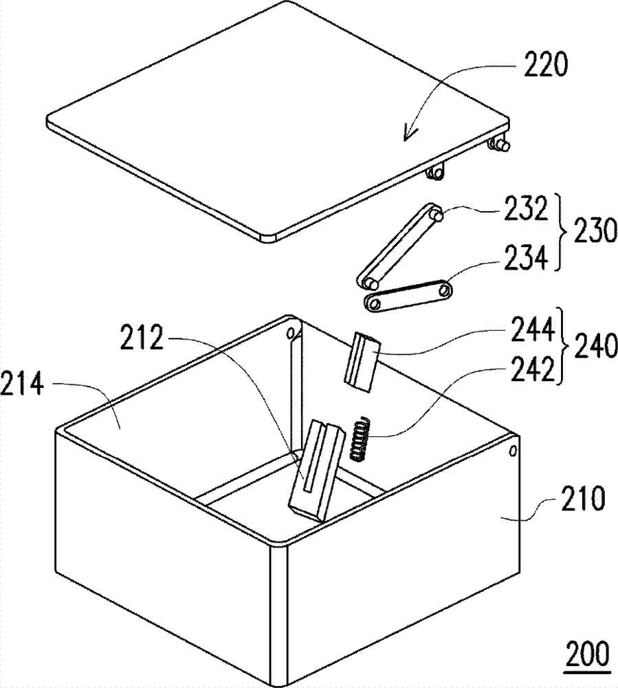
图2所示为本实用新型第一实施例的事务机的分解示意图。FIG. 2 is an exploded schematic view of the transaction machine according to the first embodiment of the present invention.
图3~图6所示为图2的事务机闭盖的作动流程示意图。3 to 6 are schematic diagrams showing the operation flow of the office closing cover in FIG. 2 .
图7所示为本实用新型第二实施例的事务机的分解示意图。FIG. 7 is an exploded schematic view of the transaction machine according to the second embodiment of the present invention.
图8所示为图7的事务机的连杆组与阻尼器相接触的局部放大图。FIG. 8 is a partial enlarged view of the contact between the connecting rod group and the damper of the business machine in FIG. 7 .
图9所示为图7的事务机的上盖相对基座开启的示意图。FIG. 9 is a schematic diagram of the upper cover of the business machine shown in FIG. 7 being opened relative to the base.
图10~图14所示为第二实施例的事务机的上盖相对基座闭盖的作动流程示意图。10 to 14 are schematic diagrams showing the operation flow of closing the upper cover of the business machine relative to the base in the second embodiment.
主要元件符号说明:Description of main component symbols:
110、220:上盖110, 220: upper cover
120、210:基座120, 210: base
130:滑动轴130: sliding shaft
140:支架140: bracket
142、244c:滑轨142, 244c: slide rail
200:事务机200: business machine
202:顶面202: top surface
212、212′:固定导轨212, 212': fixed guide rail
214:侧壁214: side wall
216:支撑点216: support point
230、230′:连杆组230, 230': connecting rod group
232、232′:第一连杆232, 232': first connecting rod
234:第二连杆234: Second link
232a:第一端232a: first end
232b:第二端232b: second end
232c:本体部232c: Main body
232d:支撑部232d: support part
234a:第三端234a: third end
234b:第四端234b: fourth terminal
240:阻尼器240: Damper
242:第一弹簧242: First Spring
244、244′:缓冲块244, 244': buffer block
244a:凸块244a: bump
246:第二弹簧246: second spring
N、D、D1、D2:方向N, D, D1, D2: direction
具体实施方式 Detailed ways
[第一实施例][first embodiment]
图2为本实用新型第一实施例的事务机的分解示意图。请参考图2,事务机200包括一基座210、一上盖220、一连杆组230以及一阻尼器240,其中本实施例的事务机200与现有的事务机相同,其上盖220上可设置有扫描仪与自动馈纸装置等,但由于扫描仪与自动馈纸装置并非本实用新型的重点,且为求图式清楚可辨,因此图中并不另示出扫描仪与自动馈纸装置。FIG. 2 is an exploded schematic view of the transaction machine of the first embodiment of the present invention. Please refer to Fig. 2,
承上所述,基座210具有一固定导轨212,且此固定导轨212设置在基座210的侧壁214上。固定导轨212可以是与基座210的壳体一体成形,或是另外以组装、黏接的方式固定在基座210的壳体上。上盖220设置于基座210上,且上盖220适于相对基座210开启。在本实施例中,事务机200具有一顶面202(如图3示),且顶面202具有一法线方向N(如图3示),而固定导轨212的长度方向D(如图3示)与法线方向N夹一锐角。此外,上盖220的一侧固定于基座210上,所以上盖220以旋转的方式相对基座210开启。连杆组230连接于基座210与上盖220之间,而设置于基座210的阻尼器240包括一第一弹簧242以及一缓冲块244,其中第一弹簧242设置于基座210的固定导轨212内,并适于沿着固定导轨212的长度方向D变形。缓冲块244的一部分嵌入于固定导轨212内,且第一弹簧242连接于固定导轨212及缓冲块244之间,而因应第一弹簧242的变形而使缓冲块244可沿着固定导轨212移动。Based on the above, the
另外,上述的连杆组230包括一第一连杆232以及一第二连杆234,第一连杆232具有一第一端232a以及一第二端232b,其中第一端232a连接于上盖220,而第二连杆234具有一第三端234a以及一第四端234b,且第三端234a与第二端232b连接,而第四端234b与基座210连接。In addition, the connecting rod set 230 includes a first connecting
图3~图6为图2的事务机闭盖的作动流程示意图。如图3示,一般而言,上盖220相对基座210呈现开启的状态时,上盖220以其连接于基座210的一侧为轴心,而未连接于基座210的另一侧相对远离基座210。此时,连杆组230并未与阻尼器240接触。接着请同时参考图3、图4及图5,欲使上盖220相对基座210闭盖时,可以是使用手动、程式控制或是电动的方式让上盖220以其连接于基座210的一侧为轴心,而未连接于基座210的另一侧以顺时针的方向转动以相对靠近基座210。受到上盖220的转动而影响,连杆组230也跟着作动,其中第一连杆232受上盖220的带动而移动,同时也略微地顺时针转动,且在此同时第二连杆234受到第一连杆232的运动而影响,第二连杆234的第三端234a以第四端234b为轴心顺时针转动,且连杆组230进而接触阻尼器240的缓冲块244。此处并不局限是第一连杆232的第二端232b或是第二连杆234的第三端234a接触阻尼器240的缓冲块244,连杆组230实际接触阻尼器240的缓冲块244的部份,依照连杆组230及阻尼器240因应设计需求的实际配置关系而定。3 to 6 are schematic diagrams of the operation flow of the closing cover of the office in FIG. 2 . As shown in FIG. 3 , generally speaking, when the
由于固定导轨212的设置方式并非是其长度方向D与法线方向互相平行或是互相垂直,而是使固定导轨212的长度方向D大致平行于连杆组230的第一连杆232的第二端232b及第二连杆234的第三端234a的连接处在闭盖程序中可能会移动的轨迹方向,因此在闭盖的过程中,连杆组230接触阻尼器240,且上盖220的自重会进而使连杆组230持续地施压在阻尼器240的缓冲块244上。阻尼器240的缓冲块244所受的力会传递至第一弹簧242上,并且第一弹簧242受力而被压缩形变,而缓冲块244便沿着固定导轨212的长度方向D移动。值得注意的是,在连杆组230开始施压在阻尼器240的缓冲块244上的同时,第一弹簧242的弹性恢复力会提供小于上盖220下降力量的反作用力,让上盖220是相对基座210缓慢地下降,直至上盖220相对基座210闭合,如图6示。Since the setting method of the fixed
当使上盖220相对基座210开盖时,连杆组230与阻尼器240之间的作动为图3~图6的反序,且在此处不再说明。When the
相较于现有的事务机仅使用滑动轴及支架的组合,在本实施例的事务机200中,使用了具有缓冲块244及第一弹簧242的阻尼器240以提供上盖220在相对基座210闭盖时的一反馈的作用力,缓冲上盖220相对基座210闭盖的速度,可防止上盖220的重量太重而撞击基座210或伤及维护人员。此外,阻尼器240所使用的零件易于取得或制作,因此材料成本也不会昂贵,事务机200的整体成本仍能得到有效的控制。Compared with the existing business machine which only uses the combination of the sliding shaft and the bracket, in the
[第二实施例][Second embodiment]
以下将列举事务机的其他实施例以作为说明。在此必须说明的是,下述第二实施例沿用前述第一实施例的元件标号与部分内容,其中采用相同的标号来表示相同或近似的元件,并且省略了相同技术内容的说明。关于省略部分的说明可参考前述实施例,下述实施例不再重复赘述。Other embodiments of the transaction machine are listed below for illustration. It must be noted here that the second embodiment below uses the component numbers and partial content of the aforementioned first embodiment, wherein the same numbers are used to denote the same or similar components, and descriptions of the same technical content are omitted. For the description of omitted parts, reference may be made to the foregoing embodiments, and the following embodiments will not be repeated.
图7为本实用新型第二实施例的事务机的分解示意图、图8为图7的事务机的连杆组与阻尼器相接触的局部放大图,而图9为图7的事务机的上盖相对基座开启的示意图。请同时参考图7、图8及图9,本实施例的固定导轨212′的长度方向D1平行于法线方向N。此外,缓冲块244′具有一凸块244a以及一缓冲块本体244b,其中缓冲块本体244b更具有一滑轨244c,而凸块244a适于嵌入于滑轨244c,以限制缓冲块244′的凸块244a只能沿着平行于顶面202的方向D2移动。阻尼器240还包括设置于滑轨244c与凸块244a之间的一第二弹簧246。Fig. 7 is an exploded view of the office machine according to the second embodiment of the present invention; Fig. 8 is a partially enlarged view of the connecting rod group of the office machine in Fig. 7 in contact with the damper; and Fig. 9 is an upper part of the office machine in Fig. Schematic illustration of the lid opening relative to the base. Please refer to FIG. 7 , FIG. 8 and FIG. 9 at the same time, the length direction D1 of the fixed
此外,基座210还具有一支撑点216,而第一连杆232′具有一本体部232c以及一支撑部232d,其中本体部232c具有第一端232a(标示于图3)以及第二端232b(标示于图3),而支撑部232d自本体部232c延伸,且支撑部232d的延伸方向(未标示)与本体部232c的长度方向(未标示)不互相平行。In addition, the
图10~图14为第二实施例的事务机的上盖相对基座闭盖的作动流程示意图。请先参考图9,当上盖220相对基座210开启时,第一连杆232′的支撑部232d会抵靠于支撑点216上,以保持上盖220持续相对基座210开启的状态。接着如图10~图12示,推移使上盖220相对基座210闭盖,受到上盖220移动的影响,连杆组230′的第一连杆232′的支撑部232d离开支撑点216,且连杆组230′抵靠于缓冲块244′,并且对缓冲块244′施加沿着固定导轨212′的长度方向D1且往下的力量,使第一弹簧242(标示于图3)受力而被压缩,且缓冲块244′也跟着沿着固定导轨212′的长度方向D1往下移动。10 to 14 are schematic diagrams of the action flow of closing the upper cover of the business machine relative to the base in the second embodiment. Please refer to FIG. 9 , when the
接着请同时参考图8及图13,特别的是,因应第一连杆232′的长度是固定且不会改变的,在上盖220相对基座210闭盖且连杆组230′下压缓冲块244′到一定程度的时候,连杆组230′(标示于图10)会推移缓冲块244′的凸块244a,且搭配凸块244a及滑轨244c的设置,凸块244a会有平行于顶面202的方向D2的移动,以顺应地消除因为第一连杆232′的长度而可能引起的闭盖程序的不顺畅。之后如图14示,上盖220与基座210闭合。Then please refer to Figure 8 and Figure 13 at the same time, in particular, because the length of the first connecting rod 232' is fixed and will not change, when the
而使上盖220相对基座210开盖时,连杆组230′与阻尼器(未标示)的作动情形为图9~图14的反序,便不再详述。其中,当连杆组230′受到上盖220的带动而移动并解除对凸块244a的限位时,第二弹簧244a及第一弹簧242的弹性恢复力使缓冲块244′回复至原位。When the
综上所述,在本实用新型的事务机中,阻尼器的设置可以提供连杆组受上盖的重量下压时的反馈力量,以减缓上盖相对基座闭盖的速度,避免上盖与基座互相撞击,不但可以保护设置在基座内的电子元件,也可以防止使用者受伤。另外,应用在本实用新型的事务机中的阻尼器的零件都是易于制造、取得及组装的零件,所以阻尼器的制作及组装成本都不贵,事务机的整体成本能够有效地获得控制。To sum up, in the office machine of the present utility model, the setting of the damper can provide the feedback force when the connecting rod group is pressed down by the weight of the upper cover, so as to slow down the closing speed of the upper cover relative to the base, and avoid the upper cover Collision with the base not only protects the electronic components arranged in the base, but also prevents the user from being injured. In addition, the parts of the damper used in the business machine of the present invention are easy to manufacture, obtain and assemble, so the manufacturing and assembly costs of the damper are not expensive, and the overall cost of the business machine can be effectively controlled.
虽然本实用新型已以实施例揭示如上,然其并非用以限定本实用新型,任何所属技术领域中的普通技术人员,当可作些许改动与润饰,而不脱离本发明的精神和范围。Although the present invention has been disclosed above with the embodiments, it is not intended to limit the present invention, and any person skilled in the art may make some changes and modifications without departing from the spirit and scope of the present invention.
Claims (8)
Applications Claiming Priority (2)
| Application Number | Priority Date | Filing Date | Title |
|---|---|---|---|
| TW100146882A TWI505942B (en) | 2011-12-16 | 2011-12-16 | Multifunction printer |
| TW100146882 | 2011-12-16 |
Publications (1)
| Publication Number | Publication Date |
|---|---|
| CN202495988U true CN202495988U (en) | 2012-10-17 |
Family
ID=47002199
Family Applications (1)
| Application Number | Title | Priority Date | Filing Date |
|---|---|---|---|
| CN2012200846153U Expired - Fee Related CN202495988U (en) | 2011-12-16 | 2012-03-08 | business machine |
Country Status (2)
| Country | Link |
|---|---|
| CN (1) | CN202495988U (en) |
| TW (1) | TWI505942B (en) |
Cited By (2)
| Publication number | Priority date | Publication date | Assignee | Title |
|---|---|---|---|---|
| CN102905049A (en) * | 2012-10-18 | 2013-01-30 | 卡莱泰克图像系统(苏州)有限公司 | Scanner |
| CN110324506A (en) * | 2018-03-28 | 2019-10-11 | 佳能株式会社 | Image-reading device and imaging device |
Families Citing this family (3)
| Publication number | Priority date | Publication date | Assignee | Title |
|---|---|---|---|---|
| TWI553432B (en) | 2013-12-12 | 2016-10-11 | 金寶電子工業股份有限公司 | Buffer structure and office machine |
| TWI558283B (en) * | 2014-07-04 | 2016-11-11 | 樺漢科技股份有限公司 | Point of sale device |
| TWI577170B (en) * | 2014-07-18 | 2017-04-01 | 信泰光學(深圳)有限公司 | Scanner and hinge module thereof |
Family Cites Families (6)
| Publication number | Priority date | Publication date | Assignee | Title |
|---|---|---|---|---|
| DE19827210C1 (en) * | 1998-06-18 | 1999-12-16 | Oce Printing Systems Gmbh | Fixing station for fixing toner images on a carrier material with a movable cover device |
| DE10213498C1 (en) * | 2002-03-26 | 2003-04-24 | Oce Printing Systems Gmbh | Safety device for cover movable between recording medium, heat radiator in fixing station of electrophotographic printer or copier has gas pressure spring in guide channel next to pulley |
| TWI291441B (en) * | 2002-08-13 | 2007-12-21 | Thn Shong Ind Co Ltd | Garbage storage device |
| KR20040081295A (en) * | 2003-03-14 | 2004-09-21 | 엘지전자 주식회사 | Spring holder assembly for drum washer |
| TWM312517U (en) * | 2006-10-14 | 2007-05-21 | Ming-Hung Gau | Rubbish bin with pedal |
| TWI331026B (en) * | 2007-12-28 | 2010-10-01 | Jin Shan Jiang | Auxiliary descending structure for a toilet seat |
-
2011
- 2011-12-16 TW TW100146882A patent/TWI505942B/en not_active IP Right Cessation
-
2012
- 2012-03-08 CN CN2012200846153U patent/CN202495988U/en not_active Expired - Fee Related
Cited By (3)
| Publication number | Priority date | Publication date | Assignee | Title |
|---|---|---|---|---|
| CN102905049A (en) * | 2012-10-18 | 2013-01-30 | 卡莱泰克图像系统(苏州)有限公司 | Scanner |
| CN110324506A (en) * | 2018-03-28 | 2019-10-11 | 佳能株式会社 | Image-reading device and imaging device |
| US11347178B2 (en) | 2018-03-28 | 2022-05-31 | Canon Kabushiki Kaisha | Image reading apparatus and image forming apparatus |
Also Published As
| Publication number | Publication date |
|---|---|
| TW201325922A (en) | 2013-07-01 |
| TWI505942B (en) | 2015-11-01 |
Similar Documents
| Publication | Publication Date | Title |
|---|---|---|
| CN202495988U (en) | business machine | |
| CN101021697B (en) | Open and close device for manuscript impaction plate | |
| CN205169479U (en) | Built -in garbage bin switch structure and garbage bin of button spring | |
| KR101165888B1 (en) | Apparatus for opening or closing plate pressing manuscript and office equipment with the same | |
| JP5807943B2 (en) | Document crimping plate opening and closing device and office equipment | |
| JPH10315570A (en) | Apparatus for opening closing document retainer plate | |
| JP2011227370A5 (en) | ||
| CN101412476B (en) | Mechanism for driving paper stop by connecting rod | |
| JP3963390B2 (en) | Document crimping plate opening and closing device and office equipment | |
| CN207242602U (en) | It is a kind of to delay out with upper cover and bung delays the dustbin of drop function | |
| US10697220B2 (en) | Counterbalance door dampener system and method for automatic duplexing units | |
| CN101391577A (en) | Oil tank cover opening mechanism | |
| CN101179610B (en) | Flip support structure of mobile phone | |
| JP4518760B2 (en) | Piano stringing device | |
| CN211443670U (en) | Garbage can with limiting structure | |
| CN217274251U (en) | Lighter | |
| JP2011028078A (en) | Opening and closing device of document pressing plate | |
| CN101742024B (en) | Hinge device for business machine | |
| CN221703494U (en) | Hinges and opening and closing devices | |
| JP3668539B2 (en) | Document crimping plate mounting device | |
| CN213838187U (en) | A hinge with rebound function | |
| CN203122157U (en) | Frying and roasting machine | |
| CN202539906U (en) | Auxiliary processing device for alkaline cells | |
| JP5893880B2 (en) | Opening and closing device for document crimping plate in office automation equipment | |
| CN208581531U (en) | Arrange velar plate elastic slice locking mechanism in side |
Legal Events
| Date | Code | Title | Description |
|---|---|---|---|
| C14 | Grant of patent or utility model | ||
| GR01 | Patent grant | ||
| CF01 | Termination of patent right due to non-payment of annual fee |
Granted publication date: 20121017 Termination date: 20160308 |
|
| CF01 | Termination of patent right due to non-payment of annual fee |