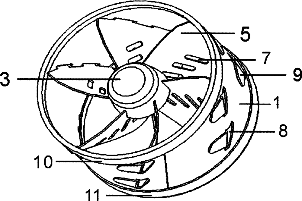
The air swirl pressurized machine
Technical field
The utility model relates to a kind of pressurized machine, particularly a kind of air swirl pressurized machine.
Background technique
Motor is to rely on gasoline and air to burn in cylinder combustion to produce power; The amount of fuel of being imported receives the restriction that sucks air in the cylinder; If the ride quality of motor has been in the optimum state, increase output power again, can only be through the compression more air; Getting into cylinder increases burning capacity, to improve the work by combustion ability.In the market, many auto makers mostly adopt turbosupercharger to improve the output power of motor.Turbosupercharger is to utilize the waste gas of discharging after the motor work done, and air-flow is made inertia impulsive force, promotes the turbine in the turbine chamber; Turbine drives coaxial impeller again, the air that the impeller force feed is sent here by the air-strainer pipeline, the i.e. air-flow that sucks of piston and make it supercharging and get into cylinder; When engine speed speeds, the waste gas velocity of discharge and secondary speed speed synchronously, and impeller just compresses more air and gets into cylinder; Pressure and density with pressurized air; Increase the more fuel of burning, but need corresponding increase amount of fuel and adjust the rotating speed that starts, thereby increase the output power of motor.Though turbosupercharger can improve the output power of motor to a certain extent; But have following defective: (1) response that lags behind: since the effect of inertia of impeller to throttle when rapid reacting condition slow; Even the reaction time after the improvement is also wanted 1.7 seconds; Engine postpone to be increased or reduce output power, this quicken suddenly for needs or the automobile of overtaking other vehicles for, moment can be put forward not sensation energetically a little; (2) can not car just walk, after the engine start, winter particularly, also to let its idling a period of time so that before supercharger rotor runs up, let its lubricant oil sufficient lubrication bearing; (3) can not be suddenly behind the automobile starting Hong throttle, otherwise can damage the pressurized machine oil sealing, and after the engine long time changes at a high speed, can not stop working immediately, because some engine oil supplying turbocharger rotor bearing lubrication and be used to cool off during engine operation; (4) after the motor that is moving was shut down suddenly, engine oil pressure dropped to zero rapidly, in the middle of booster turbine part high temperature forwards to; Heat in the bearing supporting shell can not be taken away rapidly and supercharger rotor high speed rotating under effect of inertia still simultaneously; Therefore, if engine thermal machine state is shut down down suddenly, can cause that the machine oil that is detained in the turbosupercharger is overheated and damage bearing; So big load of motor; Behind the long-play, before flame-out, answer idle running 3~5min, it is flame-out more later on to let the supercharger rotor rotating speed descend; (5) manufacture difficulty is high, costs an arm and a leg.
The model utility content
The purpose of the utility model be to overcome the deficiency of existing technology and provide a kind of simple in structure, cost is low, handling good, can promote engine power rapidly and make the engines fuel-economizing rate reach 7%-10% and can realize the air swirl pressurized machine of environmental protection purpose through reducing by 40%~50% exhaust emissions.
The purpose of the utility model realizes through following technological scheme: a kind of air swirl pressurized machine; Comprise a urceolus; Be provided with three groups of blades in the described urceolus, it is characterized in that: in urceolus, also be provided with guiding cone, described guiding cone is provided with skewed slot; The described blade of respectively organizing comprises two lamellar bodies; Form the circular arc angle of one 60 degree between two lamellar bodies; Three groups of blades are divided into six equal portions with urceolus, and in urceolus, form a spiral rotation angle of lift, and the lamellar body of every group of blade engages with skewed slot on the guiding cone and is fixedly connected with urceolus.
As a kind of improvement of the utility model, described blade is provided with the hole of streaming of growth oval type, streams the rotational speed that the hole can strengthen eddy flow, thereby helps regulating the atomizing ratio of air and fuel oil.
As a kind of improvement of the utility model, described urceolus is provided with positioning hole.
As improving again of the utility model, the end of described its lamellar body of blade is provided with the leaf pin, and leaf welded in outer drum outer wall after wearing the positioning hole on the urceolus.
As improving again of the utility model, described blade lamellar body becomes cambered surface, and the chord length of cambered surface equals cambered surface radius and multiply by spiral rotation angle of lift.
As improving again of the utility model, described urceolus comprises prosopyle and deutostoma, on described prosopyle, is provided with preceding mouth sealing ring, on described deutostoma, is provided with the back mouth sealing ring.
As improving again of the utility model, described preceding mouth sealing ring is provided with draw-in groove, and described urceolus prosopyle engages with draw-in groove.
As improving again of the utility model, described back mouth sealing ring is provided with draw-in groove, and described urceolus deutostoma engages with draw-in groove.
The beneficial effect that the utility model is obtained: the pressurized machine of the utility model adopt three groups of blades, and every group of blade comprises two lamellar bodies; Form the circular arc angle of one 60 degree between two lamellar bodies, three groups of blades are divided into six equal portions with urceolus, and the blade of this kind structure can form a spiral interflow angle of lift in urceolus; When the piston type motor air-breathing; Air-flow flows into spiral interflow angle of lift, and the instantaneous speedup of flow velocity produces high-pressure spray, contains oxygen density and increases; Instantaneous fuel oil with gasification mixes and reaches optimal air-fuel ratio; Make nonflammable gasoline additive, fully burning increases motor and exports more power, not only simple in structure, cost is low, handling good, can promote engine power rapidly and make the engines fuel-economizing rate reach 7%-10% and can realize the purpose of environmental protection through reducing by 40%~50% exhaust emissions.
Description of drawings
Fig. 1 is the perspective view of the utility model;
Fig. 2 is the utility model urceolus perspective view;
Fig. 3 is a mouth sealing ring perspective view before the utility model;
Fig. 4 is a mouth sealing ring perspective view behind the utility model;
Fig. 5 is the utility model guiding cone perspective view;
Fig. 6 is the utility model blade perspective view.
Embodiment
Below in conjunction with accompanying drawing the utility model is done further to specify:
Referring to Fig. 1, Fig. 5 and Fig. 6, the perspective view of the utility model, the air swirl pressurized machine of the utility model comprises a urceolus 1, is provided with three groups of blades 2 and a guiding cone 3 in the urceolus 1, guiding cone 3 is provided with skewed slot 4; Each is organized blade 2 and comprises two lamellar bodies 5; 56, three groups of blades of circular arc angle that form one 60 degree of two lamellar bodies are divided into six equal portions with urceolus 1, and in urceolus, form a spiral rotation angle of lift; The lamellar body 5 of every group of blade 2 engages with skewed slot 4 on the guiding cone 3, and is fixedly connected with urceolus 1.
Referring to Fig. 6 preferably, in order to strengthen the rotational speed of eddy flow, thereby help regulating the atomizing ratio of air and fuel oil, what also be provided with growth oval type on the blade streams hole 7.
Referring to Fig. 2 and Fig. 6, preferably, on urceolus, be provided with positioning hole 8; The end of blade 2 its lamellar bodies 5 is provided with leaf pin 9; 5 one-tenth cambered surfaces of blade 2 lamellar bodies, and the chord length of cambered surface equals cambered surface radius and multiply by spiral rotation angle of lift, and weld in urceolus 1 outer wall positioning hole 8 backs that leaf pin 9 passes on the urceolus 1.
Referring to Fig. 1 and Fig. 2; Preferably; Described urceolus 1 comprises prosopyle and deutostoma; Must detect through interior round cubing behind 1 one-tenth circle of urceolus, thereby the Location accuracy of losing circle and will influence the rotation angle of lift because of the positioning hole 8 on urceolus 1 and the urceolus 1 as urceolus circularity influences the air-flow angle eddy flow acceleration of making a match, and then influence flow velocity.
Referring to Fig. 3 and Fig. 4; Mouth sealing ring 10 before on described prosopyle, being provided with is provided with back mouth sealing ring 11 on described deutostoma, on the preceding mouth sealing ring and back mouth sealing ring 11 all is provided with draw-in groove 12; Described urceolus prosopyle engages with draw-in groove 12, and described urceolus deutostoma engages with draw-in groove 12.Before mouth sealing ring 10 are envelope close pressurized machine and suction tude internal face making incoming flow (air-flow that flows to from the air-strainer direction) not form crossfire (gap between interior warp of suction tude and the pressurized machine cylindrical) and influence the air-flow of pressurized machine; Eddy flow; Stream is pressed; Back mouth sealing ring 11 is the same with the effect of preceding mouth sealing ring 10, but back mouth sealing ring 11 directions to the motor direction be for 10 envelopes of mouth sealing ring preventing before close bad and remake once sealing through back mouth sealing ring 11.
The pressurized machine of the utility model adopts three groups of blades, and every group of blade comprises two lamellar bodies; Form the circular arc angle of one 60 degree between two lamellar bodies, three groups of blades are divided into six equal portions with urceolus, and the blade of this kind structure can form a spiral interflow angle of lift in urceolus; When the piston type motor air-breathing; Air-flow flows into spiral interflow angle of lift, and the instantaneous speedup of flow velocity produces high-pressure spray, contains oxygen density and increases; Instantaneous fuel oil with gasification mixes and reaches optimal air-fuel ratio; Make nonflammable gasoline additive, fully burning increases motor and exports more power, not only simple in structure, cost is low, handling good, can promote engine power rapidly and make the engines fuel-economizing rate reach 7%-10% and can realize the purpose of environmental protection through reducing by 40%~50% exhaust emissions.
According to the announcement and the instruction of above-mentioned specification, the utility model those skilled in the art can also carry out suitable change and modification to above-mentioned mode of execution.Therefore, the embodiment that discloses and describe above the utility model is not limited to also should fall in the protection domain of claim of the present invention some modifications and the change of the utility model.In addition, although used some specific terms in this specification, these terms are explanation for ease just, the utility model is not constituted any restriction.