CN202492866U - Series-parallel combined hybrid loading machine - Google Patents
Series-parallel combined hybrid loading machine Download PDFInfo
- Publication number
- CN202492866U CN202492866U CN201220088159XU CN201220088159U CN202492866U CN 202492866 U CN202492866 U CN 202492866U CN 201220088159X U CN201220088159X U CN 201220088159XU CN 201220088159 U CN201220088159 U CN 201220088159U CN 202492866 U CN202492866 U CN 202492866U
- Authority
- CN
- China
- Prior art keywords
- oil pump
- control valve
- oil
- hydraulic
- motor
- Prior art date
- Legal status (The legal status is an assumption and is not a legal conclusion. Google has not performed a legal analysis and makes no representation as to the accuracy of the status listed.)
- Expired - Fee Related
Links
- 239000003921 oil Substances 0.000 claims abstract description 73
- 230000005540 biological transmission Effects 0.000 claims abstract description 20
- 239000010720 hydraulic oil Substances 0.000 claims abstract description 12
- 229910052799 carbon Inorganic materials 0.000 abstract description 2
- 239000000446 fuel Substances 0.000 description 2
- 238000005265 energy consumption Methods 0.000 description 1
- 238000005516 engineering process Methods 0.000 description 1
- 238000000034 method Methods 0.000 description 1
- 239000002699 waste material Substances 0.000 description 1
Images

Landscapes
- Fluid-Pressure Circuits (AREA)
Abstract
本实用新型涉及一种串并混联式混合动力装载机,它由:转斗油缸、动臂油缸、动力输出轴、发动机、驱动电机、油泵传动齿轮、转向油泵、制动油泵、液力变矩器、变速器、蓄电装置、油泵电机、工作油泵、液压油箱、限压溢流阀、高压回油管、换向阀、动臂操纵阀、转斗操纵阀构成。发动机依次与动力输出轴、驱动电机、油泵传动齿轮、转向油泵、制动油泵相连接,动力输出轴依次与液力变矩器、变速器相连接,蓄电装置与驱动电机、油泵电机相连接,换向阀分别与液压油箱、工作油泵、动臂操纵阀、转斗操纵阀相连接。该产品结构简单,它利用电机的功率调节作用稳定了发动机的工作点,在液压系统不工作时,无需驱动该系统空载运行,节能减排,环保低碳。
The utility model relates to a series-parallel hybrid power loader, which is composed of: a bucket oil cylinder, a boom oil cylinder, a power output shaft, an engine, a drive motor, an oil pump transmission gear, a steering oil pump, a brake oil pump, a hydraulic variable Torque converter, transmission, power storage device, oil pump motor, working oil pump, hydraulic oil tank, pressure limiting relief valve, high pressure oil return pipe, reversing valve, boom control valve, bucket control valve. The engine is connected to the power output shaft, drive motor, oil pump transmission gear, steering oil pump, and brake oil pump in sequence, the power output shaft is connected to the hydraulic torque converter and transmission in turn, and the power storage device is connected to the drive motor and oil pump motor. The reversing valve is respectively connected with the hydraulic oil tank, the working oil pump, the boom control valve and the bucket control valve. The structure of this product is simple. It uses the power regulation function of the motor to stabilize the working point of the engine. When the hydraulic system is not working, it does not need to drive the system to run without load, saving energy and reducing emissions, and is environmentally friendly and low-carbon.
Description
技术领域:本实用新型涉及一种串并混联式混合动力装载机。Technical field: The utility model relates to a series-parallel hybrid power loader.
背景技术:传统的装载机发动机工作点比较分散,油耗高,排放量大,它的液压系统由发动机直接驱动,液压系统不工作时,仍需驱动该系统空载运行,造成了能源的极大浪费。Background technology: Traditional loader engines have relatively scattered operating points, high fuel consumption, and large emissions. Its hydraulic system is directly driven by the engine. When the hydraulic system is not working, it still needs to drive the system to run without load, resulting in a huge energy consumption. waste.
发明内容:本实用新型的目的在于克服上述缺点,提供一种串并混联式混合动力装载机,它主要解决了传统的装载机发动机工作点比较分散,油耗高,排放量大,液压系统不工作时,仍需驱动该系统空载运行等问题。本实用新型的目的是这样实现的,串并混联式混合动力装载机由:转斗油缸、动臂油缸、动力输出轴、发动机、驱动电机、油泵传动齿轮、转向油泵、制动油泵、液力变矩器、变速器、蓄电装置、油泵电机、工作油泵、液压油箱、限压溢流阀、高压回油管、换向阀、动臂操纵阀、转斗操纵阀构成。发动机与动力输出轴相连接,动力输出轴分别与驱动电机、油泵传动齿轮相连接,油泵传动齿轮分别与转向油泵、制动油泵相连接,动力输出轴与液力变矩器相连接,液力变矩器与变速器相连接,蓄电装置分别与驱动电机、油泵电机相连接,油泵电机与工作油泵相连接,工作油泵一端与液压油箱相连接,另一端与限压溢流阀相连接,换向阀一端与液压油箱相连接,另一端通过高压回油管与工作油泵相连接,换向阀分别与动臂操纵阀、转斗操纵阀相连接,转斗操纵阀与转斗油缸相连接,动臂操纵阀与动臂油缸相连接。该产品结构简单,设计合理,它采用串并混联式混合动力装载机,利用电机的功率调节作用稳定了发动机的工作点,由电机驱动液压泵工作,在液压系统不工作时,无需驱动该系统空载运行,节能减排,环保低碳。Summary of the invention: The purpose of this utility model is to overcome the above-mentioned shortcomings and provide a series-parallel hybrid loader, which mainly solves the problem of relatively scattered operating points of the traditional loader engine, high fuel consumption, large discharge volume, and poor hydraulic system. When working, it is still necessary to drive the system to run without load. The purpose of this utility model is achieved in that the series-parallel hybrid loader consists of: bucket oil cylinder, boom oil cylinder, power output shaft, engine, drive motor, oil pump transmission gear, steering oil pump, brake oil pump, hydraulic It consists of torque converter, transmission, power storage device, oil pump motor, working oil pump, hydraulic oil tank, pressure limiting relief valve, high pressure oil return pipe, reversing valve, boom control valve, and bucket control valve. The engine is connected to the power output shaft, the power output shaft is connected to the drive motor, the oil pump transmission gear, the oil pump transmission gear is connected to the steering oil pump, and the brake oil pump, and the power output shaft is connected to the hydraulic torque converter. The torque converter is connected to the transmission, the power storage device is connected to the drive motor and the oil pump motor respectively, the oil pump motor is connected to the working oil pump, one end of the working oil pump is connected to the hydraulic oil tank, and the other end is connected to the pressure limiting relief valve. One end of the directional valve is connected to the hydraulic oil tank, and the other end is connected to the working oil pump through the high-pressure oil return pipe. The directional valve is connected to the boom control valve and the bucket control valve respectively. The boom control valve is connected with the boom cylinder. The product has a simple structure and a reasonable design. It adopts a series-parallel hybrid loader, which stabilizes the operating point of the engine by using the power adjustment function of the motor. The hydraulic pump is driven by the motor. When the hydraulic system is not working, there is no need to drive the motor. The system runs without load, saving energy and reducing emissions, and is environmentally friendly and low-carbon.
附图说明: Description of drawings:
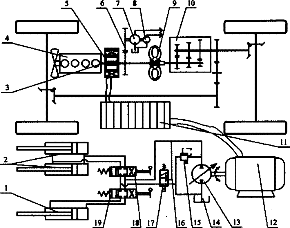
附图是本实用新型串并混联式混合动力装载机的结构示意图。The accompanying drawing is a schematic structural view of the utility model series-parallel hybrid power loader.
1-转斗油缸 2-动臂油缸 3-动力输出轴 4-发动机1-Bucket Cylinder 2-Arm Cylinder 3-Power Output Shaft 4-Engine
5-驱动电机 6-油泵传动齿轮 7-转向油泵5-Drive motor 6-Oil pump transmission gear 7-Steering oil pump
8-制动油泵 9-液力变矩器 10-变速器 11-蓄电装置8-brake oil pump 9-hydraulic torque converter 10-transmission 11-electric storage device
12-油泵电机 13-工作油泵 14-液压油箱12-Oil pump motor 13-Working oil pump 14-Hydraulic oil tank
15-限压溢流阀 16-高压回油管 17-换向阀15-Pressure limiting relief valve 16-High pressure oil return pipe 17-Reversing valve
18-动臂操纵阀 19-转斗操纵阀18-boom control valve 19-bucket control valve
具体实施方式:下面结合附图详细说明本实用新型的最佳实施例,串并混联式混合动力装载机由:转斗油缸1、动臂油缸2、动力输出轴3、发动机4、驱动电机5、油泵传动齿轮6、转向油泵7、制动油泵8、液力变矩器9、变速器10、蓄电装置11、油泵电机12、工作油泵13、液压油箱14、限压溢流阀15、高压回油管16、换向阀17、动臂操纵阀18、转斗操纵阀19构成。发动机4与动力输出轴3相连接,动力输出轴3分别与驱动电机5、油泵传动齿轮6相连接,油泵传动齿轮6分别与转向油泵7、制动油泵8相连接,动力输出轴3与液力变矩器9相连接,液力变矩器9与变速器10相连接,蓄电装置11分别与驱动电机5、油泵电机12相连接,油泵电机12与工作油泵13相连接,工作油泵13一端与液压油箱14相连接,另一端与限压溢流阀15相连接,换向阀17一端与液压油箱14相连接,另一端通过高压回油管16与工作油泵13相连接,换向阀17分别与动臂操纵阀18、转斗操纵阀19相连接,转斗操纵阀19与转斗油缸1相连接,动臂操纵阀18与动臂油缸2相连接。Specific implementation method: The best embodiment of the utility model will be described in detail below in conjunction with the accompanying drawings. The series-parallel hybrid power loader is composed of: bucket oil cylinder 1,
Claims (5)
Priority Applications (1)
| Application Number | Priority Date | Filing Date | Title |
|---|---|---|---|
| CN201220088159XU CN202492866U (en) | 2012-03-11 | 2012-03-11 | Series-parallel combined hybrid loading machine |
Applications Claiming Priority (1)
| Application Number | Priority Date | Filing Date | Title |
|---|---|---|---|
| CN201220088159XU CN202492866U (en) | 2012-03-11 | 2012-03-11 | Series-parallel combined hybrid loading machine |
Publications (1)
| Publication Number | Publication Date |
|---|---|
| CN202492866U true CN202492866U (en) | 2012-10-17 |
Family
ID=46999101
Family Applications (1)
| Application Number | Title | Priority Date | Filing Date |
|---|---|---|---|
| CN201220088159XU Expired - Fee Related CN202492866U (en) | 2012-03-11 | 2012-03-11 | Series-parallel combined hybrid loading machine |
Country Status (1)
| Country | Link |
|---|---|
| CN (1) | CN202492866U (en) |
Cited By (3)
| Publication number | Priority date | Publication date | Assignee | Title |
|---|---|---|---|---|
| CN113085525A (en) * | 2021-04-02 | 2021-07-09 | 山东玉柴机器有限公司 | Electric drive type tractor CVT power assembly with rear-mounted electric PTO structure |
| CN113147353A (en) * | 2021-04-02 | 2021-07-23 | 广西玉柴机器股份有限公司 | Electric drive type tractor CVT power assembly with mechanical through PTO structure |
| CN117306632A (en) * | 2023-10-18 | 2023-12-29 | 陕西航天动力高科技股份有限公司 | Hybrid power system of loader and method of using same |
-
2012
- 2012-03-11 CN CN201220088159XU patent/CN202492866U/en not_active Expired - Fee Related
Cited By (3)
| Publication number | Priority date | Publication date | Assignee | Title |
|---|---|---|---|---|
| CN113085525A (en) * | 2021-04-02 | 2021-07-09 | 山东玉柴机器有限公司 | Electric drive type tractor CVT power assembly with rear-mounted electric PTO structure |
| CN113147353A (en) * | 2021-04-02 | 2021-07-23 | 广西玉柴机器股份有限公司 | Electric drive type tractor CVT power assembly with mechanical through PTO structure |
| CN117306632A (en) * | 2023-10-18 | 2023-12-29 | 陕西航天动力高科技股份有限公司 | Hybrid power system of loader and method of using same |
Similar Documents
| Publication | Publication Date | Title |
|---|---|---|
| CN202115325U (en) | Driving device of power dividing hydraulic hybrid power vehicle | |
| CN102561451B (en) | Energy optimization system for hydraulic excavator | |
| CN102587444A (en) | Oil hybrid system for excavator with energy differential recovery | |
| CN103697023B (en) | For the energy regenerating of the rotary braking of engineering machinery and the electrohydraulic system of release | |
| CN202492866U (en) | Series-parallel combined hybrid loading machine | |
| CN104385896B (en) | Loader with bimotored power system | |
| CN202491670U (en) | Electromechanical coupling device of planetary mechanism for hybrid power loader | |
| CN208057549U (en) | The hydraulic system of new energy quarry tipper hydraulic lifting and fluid-link steering | |
| CN209616872U (en) | Hybrid power system of a wheeled engineering vehicle | |
| CN202656864U (en) | Hydraulic driven vehicle | |
| CN201756060U (en) | Multi-motor-driven hydraulic hybrid vehicle | |
| CN203656103U (en) | Hydraulic machinery stepless speed regulator | |
| CN204369472U (en) | For pile driver bavin electric hybrid drive system and adopt the pile driver of this system | |
| CN204899897U (en) | Double dynamical fracturing unit truck | |
| CN202621804U (en) | Large-through diameter pressure relief system for free forging oil hydraulic press | |
| CN205154784U (en) | Automatically controlled oil pipe cylinder hydraulic drive system | |
| CN203239686U (en) | Oil supplementing system for hydraulic motor | |
| CN102434646A (en) | Double-capacity hydraulic torque converter | |
| CN203130678U (en) | Hydraulic electric combined control system of horizontal directional drilling machine | |
| CN209430750U (en) | A matching hybrid automatic transmission system | |
| CN204623160U (en) | The unpowered cementing truck in chassis | |
| CN201728746U (en) | Slurry mixer truck front power take force device | |
| CN204025244U (en) | Excavator swing arm potential energy energy-recuperation system | |
| CN203926230U (en) | Three pump type hydraulic excavator oil supplying devices | |
| CN203317503U (en) | Brick maker |
Legal Events
| Date | Code | Title | Description |
|---|---|---|---|
| C14 | Grant of patent or utility model | ||
| GR01 | Patent grant | ||
| C17 | Cessation of patent right | ||
| CF01 | Termination of patent right due to non-payment of annual fee |
Granted publication date: 20121017 Termination date: 20130311 |