CN202492835U - Soil cement pile rammer compacter - Google Patents
Soil cement pile rammer compacter Download PDFInfo
- Publication number
- CN202492835U CN202492835U CN2012200019112U CN201220001911U CN202492835U CN 202492835 U CN202492835 U CN 202492835U CN 2012200019112 U CN2012200019112 U CN 2012200019112U CN 201220001911 U CN201220001911 U CN 201220001911U CN 202492835 U CN202492835 U CN 202492835U
- Authority
- CN
- China
- Prior art keywords
- support
- main support
- rammer compacter
- sliding support
- weight
- Prior art date
- Legal status (The legal status is an assumption and is not a legal conclusion. Google has not performed a legal analysis and makes no representation as to the accuracy of the status listed.)
- Expired - Fee Related
Links
- 239000004568 cement Substances 0.000 title claims abstract description 19
- 239000002689 soil Substances 0.000 title abstract description 8
- XEEYBQQBJWHFJM-UHFFFAOYSA-N Iron Chemical compound [Fe] XEEYBQQBJWHFJM-UHFFFAOYSA-N 0.000 claims abstract description 20
- 229910000831 Steel Inorganic materials 0.000 claims abstract description 15
- 239000010959 steel Substances 0.000 claims abstract description 15
- 229910052742 iron Inorganic materials 0.000 claims abstract description 10
- 230000033001 locomotion Effects 0.000 claims description 19
- 238000003466 welding Methods 0.000 claims description 9
- 239000002131 composite material Substances 0.000 abstract description 4
- 239000003638 chemical reducing agent Substances 0.000 abstract description 3
- 239000004575 stone Substances 0.000 abstract description 3
- 239000004567 concrete Substances 0.000 description 5
- 239000000203 mixture Substances 0.000 description 2
- 230000005540 biological transmission Effects 0.000 description 1
- 230000007812 deficiency Effects 0.000 description 1
- 239000000463 material Substances 0.000 description 1
- 238000000034 method Methods 0.000 description 1
- XLYOFNOQVPJJNP-UHFFFAOYSA-N water Substances O XLYOFNOQVPJJNP-UHFFFAOYSA-N 0.000 description 1
Images


Landscapes
- Piles And Underground Anchors (AREA)
Abstract
The utility model relates to a soil cement pile rammer compacter which comprises a main support, a slide support and a device support. A weight rod penetrates centers of the three supports up and down. A weight hammer is disposed on the bottom end of the weight rod. The main support is positioned under a device and is welded by square steel tubes. Four height-adjustable iron feet and bolts are arranged at bottom of the main support. The slide support is disposed over the main support and can slide left and right on the main support. The device support is arranged on the slide support and can slide back and forth on the slide support. The device support is provided with a motor, a speed reducer, two groove eccentric wheels, a weight rod baffle plate and the like. The weight hammer is in the shaped of a frustum. Through adjustment of the slide support and the device support, the weight hammer can be accurately dropped into a finished hole of a composite foundation and keeps compacting soil that is filled in the hole. The rammer compacter of the utility model has the advantages of high work efficiency, simple structure, flexible operation, convenient mounting and dismounting or the like, and can be widely used for compacting operation for soil cement piles and broken stone piles in the civil engineering field.
Description
Technical field
The utility model relates to building machinery, is specifically related to a kind of machinery of rammed concrete pile, belongs to International Classification of Patents E02F technical field.
Background technology
The rammed concrete pile Ground Treatment is a kind of novel method for processing foundation that developed recently gets up.This technology is by the common development of Inst. of Foundation, Chinese Inst. of Architectural Sciences and Hebei Prov. Architecture Science Academy; Be to utilize manually digging hole or mechanical hole building; Cement, earth material and water are are fully mixed and stirred, and then the stake that mix is successively inserted in the hole and become through the compacting of external force machinery.And existing cement earth pile rammer compacter, exist bulky, move dumb, the problem that weight and composite foundation pore-forming are difficult for aligning.
Summary of the invention
The purpose of the utility model is to overcome above-mentioned deficiency of the prior art, provides a kind of weight that lets fall into the composite foundation pore-forming, also can tamp the cement earth pile rammer compacter that bankets in the hole continuously.
The purpose of the utility model realizes through following technical scheme.
A kind of cement earth pile rammer compacter, this device comprise cubical main support, sliding support and equipment supporter three parts composition.Through the center of said three supports, weight is equipped with in the movement weight rod bottom to movement weight rod up and down.Main support is located in the bottom of device, and sliding support is installed in the main support top and is connected, can on main support, horizontally slips with the upper side frame of main support.Equipment supporter be installed in sliding support above, slide before and after can be on sliding support, motor, reductor and two groove eccentric wheels are housed on the equipment supporter.
Described main support is welded by square steel pipe and is cube, and four legs of main support below are separately installed with iron pin and adjustment bolt, the nut of a sliding support adjustment of the centre position welding bolt on right side, main support top.Long 1.2 meters, wide 1.2 meters, high 1.2 meters of main support.
Described sliding support is a rectangle support that is welded by square steel pipe, is welding the nut of an equipment supporter adjustment bolt in the place ahead of sliding support.
The left side of said equipment supporter is equipped with a motor, reaches the two shaft reductors that connect through belt with motor, and two groove eccentric wheels that have axle are housed in the middle of the equipment supporter, and the movement weight rod baffle plate.
Described weight is shaped as a frustum, and this frustum upper base diameter is 35 centimetres, and the diameter of going to the bottom is 30 centimetres, and height is 35 centimetres.The movement weight rod diameter of the position welding at frustum upper bottom surface center is 5 centimetres.
The utility model behind adjustment sliding support and equipment supporter, can let weight fall in the pore-forming of composite foundation exactly, and can tamp in the hole continuously and banket.Weight ramming each time is to lean on the eccentric rotation of groove, weight is improved 1 meter after, and the motion that makes weight form approximate freely falling body comes the rammed concrete pile body.The rammer compacter of the utility model has high efficiency, and simple in structure, flexible operation, peace are torn advantages such as convenient open, can be widely used in the Ramming operation of civil engineering cement earth pile and broken stone pile aspect.
Description of drawings
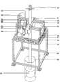
Fig. 1 is the overall structure sketch map of cement earth pile rammer compacter;
Fig. 2 be among Fig. 1 the iron pin and the adjustment bolt sketch map;
Fig. 3 is the sketch map of sliding support and equipment supporter adjustment bolt among Fig. 1;
Fig. 4 is the eccentric sketch map of Fig. 1 further groove;
Fig. 5 is the sketch map of weight plate baffle plate among Fig. 1;
Fig. 6 is the sketch map of weight among Fig. 1;
Among the figure: 01, the eccentric axle of groove; 02, motor; 03, motor output shaft; 04, belt; 05, chain; 06, sprocket wheel; 07, reductor power shaft; 08, reductor; 09, weight; 10, movement weight rod; 11, groove eccentric wheel; 12, damper rod; 13, baffle plate; 14, equipment supporter; 16, sliding support adjustment bolt; 17, sliding support; 18, main support; 19, equipment supporter adjustment bolt; 20, iron pin and adjustment bolt; 21, self-locking device; 22, speed reducer output shaft; 23, stake hole.
The specific embodiment
Referring to Fig. 1-Fig. 6, the cement earth pile rammer compacter of the utility model is made up of main support 18, sliding support 17, equipment supporter 14 three parts.Main support 18 is by the be welded square of (1.2 meters, wide 1.2 meters, high 1.2 meters in length) of square steel pipe, below four vertical column steel pipes, an iron pin and adjustment bolt 20 is installed respectively, through swivel bolt, and can be with main support 18 leveling.The nut that a sliding support is adjusted bolt 16 is being welded on right side in main support 18 the superiors.
Sliding support 17, is welded by square steel pipe by long 1.2 meters, wide 1.0 meters.The square steel pipe of the long limit of sliding support 17 and main support 18 top sides stacks, through the rotational slide support bracket bolt, but the distance of 20 centimetres of sliding support 17 move left and right.Welding the nut of an equipment supporter adjustment bolt 19 in the sliding support front side; Intersection point place at sliding support right side and sliding support adjustment bolt 16 is equipped with a self-locking device 21.
The utility model cement earth pile rammer compacter, weight ramming each time is to lean on the eccentric rotation of groove, weight is improved 1 meter after, and the motion that makes weight form approximate freely falling body comes the rammed concrete pile body.This rammer compacter has high efficiency, and simple in structure, flexible operation, peace are torn advantages such as convenient open, thereby can be widely used in the Ramming operation of civil engineering cement earth pile and broken stone pile.
During application, move rammer compacter, and the center of rammer compacter and the position in concrete stake hole are aligned basically; The steel pipe of the outstanding iron plates of four iron pin and adjustment bolt 20 bottoms of rammer compacter is firmly entered in the ground, rotate iron pin and adjustment bolt 20, make the top level that is in basically of main support 18; Rotate sliding support adjustment bolt 16 and equipment supporter adjustment bolt 19; The center in a hole and the center of weight are coincided, open movement weight rod baffle plate 13, weight 09 is put into rammer compacter; And clamp movement weight rod 10 with the groove of groove eccentric wheel 15, again movement weight rod baffle plate 13 is resetted; After the energising, motor 02 drives reductor 08 and rotates, and two output shafts (wheel) 22 of reductor 08 drive the eccentric axle 01 of groove respectively and rotate round about, and groove eccentric wheel 11 is also followed and made counter-rotation; When two eccentric drop center wheels 11 commentaries on classics are clamped movement weight rod 10 jointly; Weight 09 is promoted, and when two eccentric drop center wheels 11 can't clip movement weight rod 10, weight 09 fell; Ram the cement-soil pile body; Along with ramming of weight, the cement-soil that manual work will be mixed and stirred is dosed in the hole uniformly, till ramming required design height.At last, mobile rammer compacter carries out the compacting in next stake hole.
The utility model is mainly used in: earlier with structure foundation boring (diameter 400mm), after the cement-soil or the gravelly soil that will pour in the hole tamp.
Claims (6)
1. cement earth pile rammer compacter; It is characterized in that: this device comprises cubical main support (18), sliding support (17) and equipment supporter (14) three parts; Through the center of said three supports, weight (09) is equipped with in movement weight rod (10) bottom to movement weight rod (10) up and down; Main support (18) is located in the bottom of device, and sliding support (17) is installed in main support (18) top and is connected, can on main support (18), horizontally slips with the upper side frame of main support (18); Equipment supporter (14) be installed in sliding support (17) above, can before and after sliding support (17) is gone up, slide, motor (02), reductor (08) and two groove eccentric wheels (11) are housed on the equipment supporter (14).
2. cement earth pile rammer compacter according to claim 1; It is characterized in that: described main support (18) is welded by square steel pipe; Four legs of main support (18) below are separately installed with iron pin and adjustment bolt (20), the nut of a centre position sliding support adjustment bolt of welding (16) on right side, main support (18) top.
3. cement earth pile rammer compacter according to claim 1 is characterized in that: described sliding support (17) is a rectangle support that is welded by square steel pipe, is welding the nut of an equipment supporter adjustment bolt (19) in the place ahead of sliding support (17).
4. cement earth pile rammer compacter according to claim 1; It is characterized in that: the left side of said equipment supporter (14) is equipped with a motor (02), reaches the two shaft reductors (08) that connect through belt (04) with motor (02); Two groove eccentric wheels (11) that have axle (01) are housed in the middle of the equipment supporter (14), and movement weight rod baffle plate (13).
5. cement earth pile rammer compacter according to claim 1 is characterized in that: described weight (09) be shaped as a frustum, this frustum upper base diameter is 35 centimetres, the diameter of going to the bottom is 30 centimetres, height is 35 centimetres; Movement weight rod (10) diameter of the position welding at frustum upper bottom surface center is 5 centimetres.
6. cement earth pile rammer compacter according to claim 1 is characterized in that: the described main support that is welded by square steel pipe (18), long 1.2 meters, wide 1.2 meters, high 1.2 meters.
Priority Applications (1)
| Application Number | Priority Date | Filing Date | Title |
|---|---|---|---|
| CN2012200019112U CN202492835U (en) | 2012-01-05 | 2012-01-05 | Soil cement pile rammer compacter |
Applications Claiming Priority (1)
| Application Number | Priority Date | Filing Date | Title |
|---|---|---|---|
| CN2012200019112U CN202492835U (en) | 2012-01-05 | 2012-01-05 | Soil cement pile rammer compacter |
Publications (1)
| Publication Number | Publication Date |
|---|---|
| CN202492835U true CN202492835U (en) | 2012-10-17 |
Family
ID=46999070
Family Applications (1)
| Application Number | Title | Priority Date | Filing Date |
|---|---|---|---|
| CN2012200019112U Expired - Fee Related CN202492835U (en) | 2012-01-05 | 2012-01-05 | Soil cement pile rammer compacter |
Country Status (1)
| Country | Link |
|---|---|
| CN (1) | CN202492835U (en) |
-
2012
- 2012-01-05 CN CN2012200019112U patent/CN202492835U/en not_active Expired - Fee Related
Similar Documents
| Publication | Publication Date | Title |
|---|---|---|
| CN107178083B (en) | A kind of pile driver for civil engineering | |
| CN102635120B (en) | Circular deep foundation ditch is without Construction of Supporting structure and construction method | |
| CN104929125A (en) | Carrier pile construction equipment and carrier pile construction method | |
| US9399851B2 (en) | Piling apparatus and process for installation of pile assembly | |
| CN106193145B (en) | An automatic hydraulic grabbing machine for building rock-soil masonry | |
| CN205329709U (en) | Mountain region photovoltaic support foundation structure | |
| CN207453902U (en) | A kind of full circle swinging all casing drill | |
| CN202787246U (en) | Flexible pile and drainage body integral combination pile | |
| CN202492835U (en) | Soil cement pile rammer compacter | |
| CN205348160U (en) | Novel cement flour spouts two -way stirring stake machine construction equipment | |
| CN106149751A (en) | Utilize the method that quick lime brick quarrel compaction pile reinforces building construction ground | |
| CN105507320B (en) | Dam breach mechanical pile plantation dam construction machine and method thereof | |
| CN103790161B (en) | Three-dimensional moveable sand compaction pile pile system in centrifugal test | |
| CN102704479A (en) | Hydraulic hammering type concrete cast-in-place pile equipment | |
| CN210459189U (en) | Novel BNT carrier pile and construction equipment thereof | |
| CN103306278B (en) | Method for processing soft soil foundation with environment-friendly light pile | |
| CN207633149U (en) | A kind of auxiliary system of underpass construction | |
| CN107587853B (en) | Full-rotation full-casing drilling machine | |
| CN110258598B (en) | Construction method of large-diameter pebble geological cofferdam approach hole replacement structure | |
| CN215518731U (en) | Soft soil foundation pile construction equipment | |
| CN216771234U (en) | Geotechnical model test preformed hole internal tamping device | |
| Liu et al. | Development and application of the large-diameter driven cast-in-place concrete thin-wall pipe pile | |
| CN209816862U (en) | Construction supporting device of town road drainage structures | |
| CN204356765U (en) | A kind of highway subgrade improvement construction equipment | |
| CN207436961U (en) | A kind of full circle swinging all casing drill main body and full circle swinging all casing drill |
Legal Events
| Date | Code | Title | Description |
|---|---|---|---|
| C14 | Grant of patent or utility model | ||
| GR01 | Patent grant | ||
| CF01 | Termination of patent right due to non-payment of annual fee |
Granted publication date: 20121017 Termination date: 20150105 |
|
| EXPY | Termination of patent right or utility model | ||
| DD01 | Delivery of document by public notice |
Addressee: Zhang Guanglu Document name: Notification of Termination of Patent Right |