CN202492449U - Holding clamp mechanism of full-automatic glass bottle making machine - Google Patents
Holding clamp mechanism of full-automatic glass bottle making machine Download PDFInfo
- Publication number
- CN202492449U CN202492449U CN2012200353885U CN201220035388U CN202492449U CN 202492449 U CN202492449 U CN 202492449U CN 2012200353885 U CN2012200353885 U CN 2012200353885U CN 201220035388 U CN201220035388 U CN 201220035388U CN 202492449 U CN202492449 U CN 202492449U
- Authority
- CN
- China
- Prior art keywords
- spline shaft
- clamp
- glass bottle
- making machine
- hinge
- Prior art date
- Legal status (The legal status is an assumption and is not a legal conclusion. Google has not performed a legal analysis and makes no representation as to the accuracy of the status listed.)
- Expired - Fee Related
Links
- 239000011521 glass Substances 0.000 title claims abstract description 14
- 230000005540 biological transmission Effects 0.000 claims abstract description 5
- 238000000034 method Methods 0.000 description 6
- 238000004519 manufacturing process Methods 0.000 description 2
- 238000010586 diagram Methods 0.000 description 1
Images

Classifications
-
- Y—GENERAL TAGGING OF NEW TECHNOLOGICAL DEVELOPMENTS; GENERAL TAGGING OF CROSS-SECTIONAL TECHNOLOGIES SPANNING OVER SEVERAL SECTIONS OF THE IPC; TECHNICAL SUBJECTS COVERED BY FORMER USPC CROSS-REFERENCE ART COLLECTIONS [XRACs] AND DIGESTS
- Y02—TECHNOLOGIES OR APPLICATIONS FOR MITIGATION OR ADAPTATION AGAINST CLIMATE CHANGE
- Y02P—CLIMATE CHANGE MITIGATION TECHNOLOGIES IN THE PRODUCTION OR PROCESSING OF GOODS
- Y02P40/00—Technologies relating to the processing of minerals
- Y02P40/50—Glass production, e.g. reusing waste heat during processing or shaping
- Y02P40/57—Improving the yield, e-g- reduction of reject rates
Landscapes
- Surface Treatment Of Glass (AREA)
Abstract
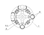
全自动玻璃制瓶机抱钳机构,气缸(2)和铰链(3)安装在下转盘(1)上,气缸(2)的活塞杆一端通过连杆与铰链(3)传动相连,花键轴安装座(4)安装在上转盘(7)上,每对花键轴(5)安装在花键轴安装座(4)内,花键轴(5)的花键轴套(5-2)通过连杆与铰链(3)传动相连,抱钳(6)通过抱钳轴安装在上转盘(7)上,花键轴(5)的摇臂(5-1)通过连杆与相邻抱钳(6)传动相连。本实用新型的优点是:将该玻璃制瓶机抱钳机构安装在玻璃制瓶机上,即可实现自动开关抱钳的开、合,代替了原有的手工操作,省时省功省力,提高了功效。
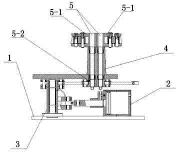
The clamping mechanism of the automatic glass bottle making machine, the cylinder (2) and the hinge (3) are installed on the lower turntable (1), the end of the piston rod of the cylinder (2) is connected to the hinge (3) through the connecting rod, and the spline shaft is installed The seat (4) is installed on the upper turntable (7), each pair of spline shafts (5) is installed in the spline shaft mounting seat (4), and the spline shaft sleeve (5-2) of the spline shaft (5) passes through The connecting rod is connected with the hinge (3), the clamp (6) is installed on the upper turntable (7) through the clamp shaft, and the rocker arm (5-1) of the spline shaft (5) is connected with the adjacent clamp through the connecting rod. (6) The transmission is connected. The utility model has the advantages that: installing the clamp mechanism of the glass bottle-making machine on the glass bottle-making machine can realize the opening and closing of the automatic switch clamp, which replaces the original manual operation, saves time, labor and effort, and improves effect.
Description
技术领域 technical field
本实用新型涉及玻璃制瓶机领域,具体地说涉及玻璃制瓶机抱钳及控制机构。The utility model relates to the field of glass bottle making machines, in particular to a clamp and a control mechanism of the glass bottle making machine.
背景技术 Background technique
目前,玻璃制瓶行业在生产及加工过程中,大部分夹瓶及转移过程中,都是通过人工手动完成,不仅工效低,而且劳动强度较大,玻璃瓶在加工时,温度较高,如果操作人员不慎将导致烫伤。At present, in the production and processing process of the glass bottle making industry, most of the bottle clamping and transfer processes are done manually, which not only has low work efficiency, but also has high labor intensity. When glass bottles are processed, the temperature is high. If Operator carelessness will result in burns.
实用新型内容 Utility model content
本实用新型的目的就是针对目前玻璃制瓶行业在生产及加工过程中,大部分夹瓶及转移过程中,都是通过人工手动完成,不仅工效低,而且劳动强度较大,玻璃瓶在加工时,温度较高,如果操作人员不慎将导致烫伤之不足,而提供一种玻璃制瓶机抱钳机构。The purpose of this utility model is to aim at the production and processing process of the current glass bottle industry. Most of the bottle clamping and transfer processes are done manually, which not only has low work efficiency, but also has high labor intensity. , the temperature is high, if the operator is not careful, it will cause burns, and a glass bottle making machine clamp mechanism is provided.
本实用新型由机下转盘、一组气缸、一组铰链、一组花键轴安装座、多对花键轴、多套抱钳和上转盘组成,气缸和铰链安装在下转盘上,气缸的活塞杆一端通过连杆与铰链传动相连,花键轴安装座安装在上转盘上,每对花键轴安装在花键轴安装座内,花键轴的花键轴套通过连杆与铰链传动相连,抱钳通过抱钳轴安装在上转盘上,花键轴的摇臂通过连杆与相邻抱钳传动相连。The utility model is composed of a lower turntable, a set of cylinders, a set of hinges, a set of spline shaft mounting seats, multiple pairs of spline shafts, multiple sets of clamps and an upper turntable. The cylinder and hinges are installed on the lower turntable, and the piston of the cylinder One end of the rod is connected with the hinge drive through the connecting rod, the spline shaft mounting seat is installed on the upper turntable, each pair of spline shafts is installed in the spline shaft mounting seat, and the spline shaft sleeve of the spline shaft is connected with the hinge drive through the connecting rod , the holding tong is installed on the upper turntable through the holding tong shaft, and the rocker arm of the spline shaft is connected with the adjacent holding tong through the connecting rod.
本实用新型的优点是:将该玻璃制瓶机抱钳机构安装在玻璃制瓶机上,即可实现自动开关抱钳的开、合,代替了原有的手工操作,省时省功省力,提高了功效。The utility model has the advantages that: installing the clamp mechanism of the glass bottle-making machine on the glass bottle-making machine can realize the opening and closing of the automatic switch clamp, which replaces the original manual operation, saves time, labor and effort, and improves effect.
附图说明 Description of drawings
图1是本实用新型结构示意图。Fig. 1 is the structural representation of the utility model.
图2是本实用新型传动原理结构示意图。Fig. 2 is a schematic structural diagram of the transmission principle of the utility model.
具体实施方式 Detailed ways
本实用新型由机下转盘1、一组气缸2、一组铰链3、一组花键轴安装座4、多对花键轴5、多套抱钳6和上转盘7组成,气缸2和铰链3安装在下转盘1上,气缸2的活塞杆一端通过连杆与铰链3传动相连,花键轴安装座4安装在上转盘7上,每对花键轴5安装在花键轴安装座4内,花键轴5的花键轴套5-2通过连杆与铰链3传动相连,抱钳6通过抱钳轴安装在上转盘7上,花键轴5的摇臂5-1通过连杆与相邻抱钳6传动相连。The utility model is composed of a lower turntable 1, a set of
工作过程:如图1、图2所示,使用前,先将此抱钳机构安装在玻璃制瓶机上,启动气缸2,当气缸2的活塞杆伸出时,活塞杆通过转动铰链3带动花键轴套5-2是花键轴5转动,花键轴5的花键轴摇臂5-1通过连杆使抱钳6处于张开状态。反之,当气缸2的活塞杆收缩时,抱钳6处于闭合状态。Working process: As shown in Figure 1 and Figure 2, before use, first install the clamp mechanism on the glass bottle making machine, start the
Claims (1)
Priority Applications (1)
| Application Number | Priority Date | Filing Date | Title |
|---|---|---|---|
| CN2012200353885U CN202492449U (en) | 2012-02-04 | 2012-02-04 | Holding clamp mechanism of full-automatic glass bottle making machine |
Applications Claiming Priority (1)
| Application Number | Priority Date | Filing Date | Title |
|---|---|---|---|
| CN2012200353885U CN202492449U (en) | 2012-02-04 | 2012-02-04 | Holding clamp mechanism of full-automatic glass bottle making machine |
Publications (1)
| Publication Number | Publication Date |
|---|---|
| CN202492449U true CN202492449U (en) | 2012-10-17 |
Family
ID=46998685
Family Applications (1)
| Application Number | Title | Priority Date | Filing Date |
|---|---|---|---|
| CN2012200353885U Expired - Fee Related CN202492449U (en) | 2012-02-04 | 2012-02-04 | Holding clamp mechanism of full-automatic glass bottle making machine |
Country Status (1)
| Country | Link |
|---|---|
| CN (1) | CN202492449U (en) |
-
2012
- 2012-02-04 CN CN2012200353885U patent/CN202492449U/en not_active Expired - Fee Related
Similar Documents
| Publication | Publication Date | Title |
|---|---|---|
| CN102126214B (en) | Manipulator for grabbing high-temperature steel plate spring | |
| CN105313131A (en) | Clamping jaw device for robot | |
| CN203956918U (en) | For the robotic arm grasping mechanism of visual identity grabbing device | |
| CN205345437U (en) | Press from both sides bottle manipulator | |
| CN102765185B (en) | Folder embryo manipulator | |
| CN202492449U (en) | Holding clamp mechanism of full-automatic glass bottle making machine | |
| CN104209954B (en) | A kind of manipulator of golf club soaking paste scab and using method thereof | |
| CN203045263U (en) | Hydraulic clamping mechanism | |
| CN202465482U (en) | Initial forming machine for glass bottle making | |
| CN204094678U (en) | A kind of fixture block chain wrench | |
| CN204525463U (en) | A kind of can the manipulator mechanism of Open valve | |
| CN105710775A (en) | Convenient internal gear clamping mechanism with hydraulic transmission device | |
| CN202106316U (en) | Energy-saving lamp holder | |
| CN202465483U (en) | Holding pliers of glass bottle making machine and control mechanism thereof | |
| CN107971717A (en) | Roller turnover mechanism | |
| CN202805620U (en) | Embryo clamping mechanical arm | |
| CN202498464U (en) | Fast bench clamp | |
| CN205766214U (en) | A kind of Pneumatic clamping jaw device | |
| CN205555877U (en) | Axle type lifting device | |
| CN204449935U (en) | Automatic clamping device | |
| CN204054073U (en) | A kind of manipulator for dipping golf head and sticking sand | |
| CN104786056B (en) | Working method of sewing machine part assembling machine | |
| CN200974804Y (en) | Special mould holding clamp for row-line type bottle making machine | |
| CN105710773A (en) | Hydraulic transmission type clamping device for polishing end face of internal gear | |
| CN105460607B (en) | The conveyer of the special bearing pin of motorcycle |
Legal Events
| Date | Code | Title | Description |
|---|---|---|---|
| C14 | Grant of patent or utility model | ||
| GR01 | Patent grant | ||
| CF01 | Termination of patent right due to non-payment of annual fee | ||
| CF01 | Termination of patent right due to non-payment of annual fee |
Granted publication date: 20121017 Termination date: 20130204 |