Efficient full-automatic oil-water separation system
Technical field
The utility model belongs to the environmental protection water treatment field, specifically, relates to the system that a kind of oily(waste)water that is used for that family kitchen and catering industry are discharged carries out efficient full-automatic oily water separation.
Background technology
The development of industries such as Along with people's growth in the living standard and hotel, food and drink, hotel progressively increases the consumption of edible oil.The edible oil residue that discharges in the kitchen is the one of the main reasons that causes river, lake water quality to grow fat along with water drain is discharged.Therefore before the oily(waste)water discharging, passing through oily water separating equipment separated and collected profit, is the important measures of avoiding water resources to be polluted.
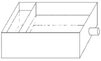
Fig. 1 shows a kind of typical structure of existing water-and-oil separator, and there is following shortcoming in it:
One, oily water separation is thorough inadequately, separation efficiency is lower, and the separation more than 60 microns that can't reach national regulation reaches 95% standard.Existing water-and-oil separator only separates profit through the oil removal weir, and when oil-water mixture got into water-and-oil separator for the first time, most waste oil was discharged to underground from bottom, oil removal weir; Waste oil is got unclean, and residual have oil; And most use flash liberations so not only cause energy dissipation, and still can residual contamination.
Two, existing water-and-oil separator is a type hand, and isolated waste oil must accumulate to a certain amount of ability and take out through artificial.Simultaneously, waste oil is of long duration in container can be rotten, and produce peculiar smell; Need carry out oil removing, remove slag operation; And mostly existing water-and-oil separator is artificial oil removing, artificial slagging-off, the operation so people are unwilling, and therefore the water-and-oil separator of most of catering trades performs practically no function.
Three, existing water-and-oil separator can only be handled a large amount of oily(waste)waters, and the oily(waste)water of a spot of or micro-(several liters are perhaps below a liter) just can't in time be handled, so be difficult to realize that family uses.Because when waste water oleaginousness seldom the time, this equipment is difficult in time to come out separating of oil, so be difficult to avoid the existence of " sewer oil ".Moreover, a large amount of waste oil in the swill bucket can not be collected, and these waste oil by lawless person's purchase, just might cause the possibility of sewer oil backflow dining table together with swill.
Four, existing water-and-oil separator is mounted in catering industry under the sink mostly, and after tableware was washed with washing composition, a part of waste oil was hydrolyzed, and causes secondary pollution, makes olefiant waste simultaneously.Under the waste oil inflow place that these are hydrolyzed, also become one of reason of " sewer oil " existence.
Five, existing water-and-oil separator is not with heating function.In the winter time or when cold district or chafing dish restaurant used, the animal oil and fat of high condensation point was difficult to be separated, they are discharged to underground, not only pollute, and become the another source of " sewer oil ".
Six, the waste water reuse after existing water-and-oil separator can not be realized separating.And intelligent inadequately mostly, controlled by Internet of Things.
The utility model content
In view of above reason, the applicant improves through research to the existing deficiency of existing water-and-oil separator, and a kind of efficient full-automatic oil-water separation system is provided.
The technical scheme of the utility model is following:
A kind of efficient full-automatic oil-water separation system, this system comprises oil spilling pond, separator box, oil storage cup and the water tank by pipe connection; Said oil spilling is provided with overflow weir in the pond, and stainless steel slagging-off net is installed in the cavity that the sidewall of overflow weir and run-off one end constitutes, and the bottom of cavity is connected with separator box through pipeline, on the pipeline that connects oil spilling pond and separator box, entering water electromagnetic valve is installed; The bottom of said separator box is the cylindricality that cross-sectional area equates, the middle part is the diminishing from bottom to top pyramid of cross-sectional area, and the pyramid top connects a shoe cream room through a slender neck; Stainless steel filtering net is installed in the separator box, and the top of said stainless steel filtering net is provided with dash plate; The neck of separator box is equipped with first sensor, and the top of dash plate 7 is equipped with second transmitter; The neck of separator box is connected with oil storage cup through pipeline, and said oil storage cup bottom is provided with water port, and its sidewall is provided with oil discharge outlet; The bottom of separator box is connected with water tank through pipeline, on the pipeline that connects separator box and water tank, drain solenoid valve is installed; The automatic bailer of being made up of water discharge valve and ball float is installed in the water tank; Water tank is connected with the oil spilling pond through pipeline, and first water pump with this pipe connection is installed in the water tank.
Its further technical scheme is: this system also comprises a swill bucket, and the oral area of said swill bucket is provided with overflow groove; Said water tank is connected with the swill bucket through pipeline, and second water pump with this pipe connection is installed in the water tank.
Its further technical scheme is: also have a press mechanism, press mechanism has two kinds of optional technical schemes.First kind of optional technical scheme is: press mechanism is arranged on the swill bucket; Said press mechanism comprises the briquetting with a scarp; The bottom of briquetting is equipped with the grid of level, and the both sides of briquetting are connected with the swill bucket through hoisting appliance, between briquetting and the swill bucket leverage is installed; Be connected with returning spring between leverage and the swill bucket, the end of leverage is a handle.Second kind of optional technical scheme is: press mechanism is independent of the swill bucket; Said press mechanism comprises the briquetting with a scarp; The bottom of briquetting is equipped with the grid of level; The both sides of briquetting are connected with frame through hoisting appliance, between briquetting and the frame leverage are installed, and the end of leverage is a hand lever.The sealing shirt rim that the peripheral flexible material of horizontal grate is made.
Its further technical scheme is: on the pipeline that connects oil spilling pond and separator box, centrifugal rotation skim gate is installed, centrifugal rotation skim gate also is installed in the oil spilling pond.
Its further technical scheme is: in the said separator box filter screen is installed, said filter screen is installed in the below of dash plate, the top of stainless steel filtering net.
Its further technical scheme is: be separately installed with electric heater unit in said separator box, oil storage cup and the water tank, on the pipeline that connects separator box and oil storage cup, be enclosed with electric heater unit.
Its further technical scheme is: this system has time-delay and pilot circuit, and said time-delay and pilot circuit connect each SV, water discharge valve and water pump, make this system according to program loop work.
The useful technique effect of the utility model is:
One, the utility model adopts the design concept of particular structure and stage trapping; Can improve oil-water separation and separation accuracy; Make the elaioleucite separation more than 50 microns reach 100%, the water outlet oil-containing is realized the zero release of waste oil basically less than 1mg/L even lower.
Two, the utility model can be realized truly self-skimming, automatic oil draining, unique multistage slagging-off, and the stage trapping mode can reduce follow-up obstruction, and stable equipment operation is easy to install, easy handling, thus reduce labor strength greatly.
Three, the utility model uses special swill bucket, can almost all take out waste oil in the dreg barrel, lets waste oil no longer under the inflow place; Perhaps flow back to dining table through approach such as lawless persons; Utilize in the water tank isolated waste water realize to a small amount of or micro-oily(waste)water (several liters, below one liter, even a few gram) instant separation, waste oil is as far as possible thoroughly taken out, avoid waste oil to be long-term stored at the problem of water-and-oil separator mesometamorphism.And conserve water resource greatly, can accomplish miniaturized, family expensesization realize combining with small-sized household dishwasher or kitchen sink, reduce a large amount of washing composition, let trench no longer include oil, the minimizing even stop the pollution of waste oil to rivers and lakes from the source.
Four, the utility model will contain the smeary tableware and put into run-off; In oil water separation process through constantly washing away; After too much wheel flushing, only need add micro-liquid detergent and just can tableware be cleaned, thereby reduce the waste oil loss, the existence of thoroughly stopping sewer oil from the source.These waste oil can be extracted out processes biofuel, anxious to separate fuel oil; Or make other purposes.
Five, the utility model has the auxiliary electrical heating function, and oil-water separation significantly improves, even the animal oil and fat of high condensation point also can basically all take out.
Six, the utility model can utilize that isolated waste water uses repeatedly in the water tank, greatly the conserve water resource.Intelligent degree is high, no matter is to use discrete component, or PLC, can realize and the docking of Internet of Things.
Description of drawings
Fig. 1 is the structural representation of existing water-and-oil separator.
Fig. 2 is the structural representation of first kind of embodiment of the utility model.
Fig. 3 is the structural representation of second kind of embodiment of the utility model.
Fig. 4 is the structural representation of the third embodiment of the utility model.
Fig. 5 is the structural representation of the 4th kind of embodiment of the utility model.
Fig. 6 is the time-delay and the pilot circuit schematic diagram of the utility model.
Among the figure: 1 oil spilling pond, 2 overflow weirs, 3 stainless steels slagging-off net
4 entering water electromagnetic valves, 5 centrifugal rotation skim gate 6 separator boxs
7 dash plates, 8 filter screens, 9 stainless steel filtering nets
10 first sensors, 11 second transmitters, 12 oil storage cups
13 drain solenoid valves, 14 water tanks, 15 water discharge valves
16 ball floats, 17 first water pumps, 17 ' the second water pumps
18 electric heater units, 19 swill buckets, 20 overflow grooves
21 briquettings, 22 grids, 23 hoisting appliances
24 leverage, 25 returning springs, 26 handles
31 briquettings, 32 grids, 33 hoisting appliances
34 leverage, 35 frames, 36 hand levers.
Embodiment
Below in conjunction with accompanying drawing, the utility model is specified through embodiment.
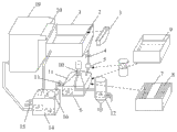
As shown in Figure 2; The utlity model has an oil spilling pond 1, when reality is used, at first oily(waste)water is extracted in the oil spilling pond 1 with water pump; Because there are density difference in water and oil; Therefore elaioleucite is flowing through overflow weir 2 through behind the unhurried current of certain hour, accomplishes profit roughing out for the first time, and oily(waste)water carries out the separation of slag liquid through removable stainless steel filtering net 3 (concrete structure is seen enlarged view) afterwards.Then, oily(waste)water removes the gred through entering water electromagnetic valve 4 controls, centrifugal rotation skim gate 5 (optional, concrete structure is seen enlarged view) once more, flows into the unique separator box 6 of structure.After dash plate 7 (seeing enlarged view) buffering, the oil in the mixture is on bubbling through the water column after the obstruct of filtering net 8 (optional, as to see enlarged view).The effect of dash plate 7 is the flow velocitys that reduce oil-water mixture, prevents that the grease in the mixture from touching following stainless steel filtering net 9, causes its obstruction, and its area is the bigger the better.Along with continuous water inlet; The continuous rising of liquid level in the separator box 6; Oil reservoir gets into the cylindrical shoe cream room at separator box 6 tops, becomes the oil column that floorage is very little, thickness is very high after the conversion of large-area oil reservoir process equal-volume, separates from the oil discharge outlet of separator box 6 necks; Flow into the cylindrical oil storage cup 12 that changes other shapes, realize that profit separates for the second time.Oil reservoir in the oil storage cup 12 is accomplished oily water separation again through behind the sufficient standing, and oil wherein takes out in order to recycling through oil discharge outlet, and waste water is wherein then discharged through water port.When the liquid level in the separator box 6 rises to certain altitude, be installed in first sensor 10 (the going up liquid level sensor) action on separator box top, send information, control entering water electromagnetic valve 4 is closed.Time delay circuit control entering water electromagnetic valve 4 separates by the profit sufficient standing in the separator box 6 at this section time delay through the time-delay of certain hour, and then oil extraction.After time-delay finished, drain solenoid valve 13 was opened, and was discharged in the water tank 14 subsequent use behind the waste water process stainless steel filtering net 9 (seeing enlarged view).Stainless steel filtering net 9 has two effects at this, and the one, elaioleucite dumpling that filtering is big and small amounts of food residue, the 2nd, the flow velocity of water outlet after reducing to separate.When the water level in the separator box 6 drops to certain altitude (stainless steel filtering net is certain position more than 9), information is sent in second transmitter 11 (following liquid level sensor) action, and control drain solenoid valve 13 is closed, and entering water electromagnetic valve 4 is opened once more.Be provided with the automatic bailer of forming by water discharge valve 15 and ball float 16 (being similar to the device in the water closet) in the water tank 14, keeping leaving enough water in the case, thereby realize waste water reuse.This automatic bailer is contained in below the water surface of water tank 14, and when the waste water that enters water tank 14 reached certain limit, the water discharge valve 15 of this automatic bailer was opened automatically, discharged unnecessary waste water, has realized an oily water separation this moment again.First water pump 17 in oil spilling pond 1, carries out the separation of second cycle with the water pump in the water tank 14.So go round and begin again, the flushing of repeated multiple times can all be reclaimed waste oil.After multiple times of filtration, there is not oil in the waste water of discharge basically.Distinctive multiple-stage treatment and tripping device, to the profit roughing out of oily(waste)water elder generation, segmentation is left again, and then the roughing out of water oil, and the segmentation of last water oil is left.Special automatic control of liquid technology does not need any additives, just can automatically the compound lard in the oily(waste)water thoroughly be separated and concentrate, and emits through post precipitation.
The utility model also can be operated like this: tableware to be washed is put into run-off 1, carry out said procedure, wash away through constantly drawing water, after several the wheel, treat that the waste oil in the wash up will swim in the water surface basically, thereby be separated.Take out them then, only need add a little liquid detergent (even not adding) just can be the tableware wash clean.So almost can thoroughly stop the existence of sewer oil.
In winter or under the lower situation of temperature, when perhaps in chafing dish restaurant, using, because temperature oil freezing point low or that have is higher, profit is not easily separated.The utility model is provided with electric heater unit 18 in separator box 6, oil storage cup 12 and water tank 14, on the pipeline that connects separator box 6 and oil storage cup 12, wrapped up electric heater unit (like electric heating cloth).So under normal circumstances, the work of native system follow procedure, promptly oily water separation is carried out in heating more earlier.If need not heat, native system also is provided with the compulsory execution button, under the situation that need not heat, presses this button, just can directly carry out oily water separation.In addition, native system also is provided with forces water inlet, forced drainage button, can be not according to procedure operation when carrying out these actions.
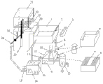
As shown in Figure 3, the utility model also can supportingly be provided with a swill bucket 19 on the basis of said structure, as the preceding road equipment of run-off 1 processing.The oral area of swill bucket 19 is provided with overflow groove 20, and in order to swill is filtered for the first time, the mixture after the filtration gets in the run-off 1 again.Accordingly, utilize second water pump 17 ' in swill bucket 19 with the water pump in the water tank 14.(or on the outlet conduit of first water pump 17, T-valve is set, the two ends of T-valve are connected run-off 1 and swill bucket 19 respectively.)
As shown in Figure 4; Except the oral area at swill bucket 19 is provided with overflow groove 20; The press mechanism of one also can be set on swill bucket 19; This press mechanism comprises that a bottom is the briquetting 21 of the wedge plungers formula on scarp, and the bottom of briquetting 21 is equipped with the grid 22 of level, the sealing shirt rim that the peripheral flexible material of horizontal grate is made.The both sides of briquetting 21 are connected with swill bucket 19 through piston-type or guide tracked hoisting appliance 23; Between briquetting 21 and the swill bucket 19 leverage 24 are installed; Be connected with returning spring 25 between leverage 24 and the swill bucket 19, the end of leverage 24 is a handle 26.During actual the use, lift on the handle 26, briquetting 21 is descended through leverage 24; Utilize 22 pairs of swills of grid to squeeze, below swill is forced into basically, along with wedge shape briquetting 21 is constantly descending; The oily(waste)water water surface constantly rises, and flows through the overflow groove 20 of oral area.Oily(waste)water is subdued wedge plungers more after a little while in the swill bucket, and the oily(waste)water liquid level just raises, and flows into the oil spilling pond again, can reach the effect of water saving.
As shown in Figure 5; Press mechanism also can be independent of swill bucket 19 and be provided with; This independently press mechanism comprise that a bottom is the briquetting 31 on scarp, the bottom of briquetting 31 is equipped with the grid 32 of level, the both sides of briquetting 31 are connected with frame 35 through piston-type or guide tracked hoisting appliance 33; Between briquetting 31 and the frame 35 leverage 34 are installed, the both side ends of leverage 24 is connected to hand lever 36.During actual the use, earlier with swill bucket 19 shift onto press mechanism below, swill bucket 19 just can be placed in the frame 35 like this, independently the main effect of press mechanism is to make that swill bucket 19 is replaceable, a plurality of swill buckets 19 can be recycled.
Fig. 6 shows the time-delay and the pilot circuit of the utility model, wherein, the 7805th, circuit of three-terminal voltage-stabilizing integrated; The IC of one 8 end of top is the monostable circuit (also available ST replaces) that constitutes by 555; The IC of one 8 end of below is the MV that constitutes by 555, and cgq1, cgq2 are respectively the first sensor and second transmitter, and kt1 ~ kt5 is a relay1 coil; M1, M2 are first water pump and second water pump, and these two water pumps can work alone or work simultaneously.Above-mentionedly also can omit by 555 monostable circuit and the MVs that constitute.
The first sensor 10 in the present embodiment and second transmitter 11 can be selected commercially available liquid-level type transmitter or probe sensor for use.In addition, entering water electromagnetic valve 4, drain solenoid valve 13 and centrifugal rotation skim gate 5 all can be selected the commercial goods for use or assembled by the commercial goods.
Above-described only is the preferred implementation of the utility model, and the utility model is not limited to above embodiment.Be appreciated that those skilled in the art under the prerequisite of spirit that does not break away from the utility model and design, can make other improvement and variation.