CN202491902U - Driving wheel of electric scooter - Google Patents
Driving wheel of electric scooter Download PDFInfo
- Publication number
- CN202491902U CN202491902U CN2012200875688U CN201220087568U CN202491902U CN 202491902 U CN202491902 U CN 202491902U CN 2012200875688 U CN2012200875688 U CN 2012200875688U CN 201220087568 U CN201220087568 U CN 201220087568U CN 202491902 U CN202491902 U CN 202491902U
- Authority
- CN
- China
- Prior art keywords
- tire
- driven
- stage casing
- bearing
- tyre
- Prior art date
- Legal status (The legal status is an assumption and is not a legal conclusion. Google has not performed a legal analysis and makes no representation as to the accuracy of the status listed.)
- Expired - Fee Related
Links
- 239000007787 solid Substances 0.000 claims abstract description 11
- 238000005265 energy consumption Methods 0.000 abstract 1
- 239000002344 surface layer Substances 0.000 abstract 1
- 238000005096 rolling process Methods 0.000 description 2
- 238000005273 aeration Methods 0.000 description 1
- 230000009286 beneficial effect Effects 0.000 description 1
- 238000007664 blowing Methods 0.000 description 1
- 238000005516 engineering process Methods 0.000 description 1
- 238000000034 method Methods 0.000 description 1
- 238000005457 optimization Methods 0.000 description 1
Images
Landscapes
- Arrangement Or Mounting Of Propulsion Units For Vehicles (AREA)
Abstract
The utility model discloses a driving wheel of an electric scooter. The driving wheel of the electric scooter comprises a long-diameter in-wheel motor, a fixed tyre, a driven tyre and a bearing. The driving wheel of the electric scooter is characterized in that a motor shell surface layer of one end of the long-diameter in-wheel motor is coated with the fixed tyre, the other end of the long-diameter in-wheel motor is provided with the bearing, the periphery of the bearing is coated with the driven tyre, and the fixed tyre and the driven tyre are both solid tyres. According to the driving wheel of the electric scooter, when the electric scooter changes a direction, a differential between the inner end and the outer end of the driving wheel is achieved; tyre wear, power and energy consumption are reduced; air inflation is not needed; and operation safety is improved.
Description
Technical field
The utility model relates to a kind of Segway Human Transporter wheel, is specifically related to a kind of Segway Human Transporter drive wheel.
Background technology
Segway Human Transporter turns to when going, because outboard wheels is bigger than the distance that inboard wheel moves past, if the both sides wheel is captiveed joint with axle drive shaft, with making outboard wheels when rolling, produce sliding dragging, and inboard wheel produces in rolling and trackslips.Wheel not only aggravates wear on tyres, increases power and expenditure of energy when sliding, also can make Segway Human Transporter turn to difficulty, deceleration and stopping performance variation.
At present, mostly the tire of Segway Human Transporter is air-inflation tyre, and aerification in the tire if run into the hot or higher load of weather, the phenomenon of blowing out occurs easily, brings potential safety hazard.
Summary of the invention
The problem that the utility model will solve is: design a kind of Segway Human Transporter drive wheel, reduce wear on tyres, depowering and expenditure of energy when turning to, and need not inflation, improve safety in operation.
The technical scheme that its technical matters that will solve the utility model adopts is: design a kind of Segway Human Transporter drive wheel; Comprise major diameter wheel hub motor, fixedly tire, driven tire and bearing; It is characterized in that: the said major diameter wheel hub motor one end motor housing top layer tire that is coated and fixed; The other end is installed bearing, and the bearing periphery coats driven tire; Said fixedly tire and driven tire are band tyres; Said major diameter wheel hub motor stage casing coats the stage casing cover tire; Said fixedly tire comprises solid inner tube and cover tire, and driven tire comprises solid inner tube and cover tire, and solid inner tube and cover tire form an integral body; Said fixedly Outer Tyre is connected with the stage casing cover tire, and driven tire and stage casing cover tire are separated; Said fixedly tire and stage casing cover tire are separated, and driven Outer Tyre is connected with the stage casing cover tire, and bearing is installed on motor housing top layer, major diameter wheel hub motor stage casing.
The beneficial effect that the utility model had is: use the utility model, when Segway Human Transporter turns to, realize the differential at the inside and outside two ends of drive wheel, reduce wear on tyres, depowering and expenditure of energy, and need not inflation, improved safety in operation.
Description of drawings
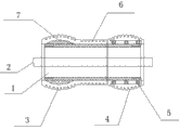
Fig. 1 is the utility model structural representation;
Among the figure: 1. major diameter wheel hub motor, 2. motor shaft, 3. fixing tire, 4. driven tire, 5. bearing, 6. stage casing cover tire, 7. solid inner tube.
The specific embodiment
As shown in fig. 1; A kind of Segway Human Transporter drive wheel of the utility model; Comprise major diameter wheel hub motor 1, fixedly tire 3, driven tire 4 and bearing 5; One end motor housing top layer of major diameter wheel hub motor 1 tire 3 that is coated and fixed, the other end of major diameter wheel hub motor 1 is installed bearing 5, and bearing 5 peripheries coat driven tire 4; Fixedly tire 3 is band tyres with driven tire 4, and motor shaft 2 is the wheel shaft of Segway Human Transporter drive wheel.
Present technique scheme optimization major diameter wheel hub motor 1 stage casing coats stage casing cover tire 6, and fixedly tire 3 comprises solid inner tube 7 and cover tire, and driven tire 4 comprises solid inner tube 7 and cover tire, and solid inner tube 7 forms an integral body with cover tire, need not inflation; Fixedly the cover tire of tire 3 is connected with stage casing cover tire 6, and driven tire 4 is separated with stage casing cover tire 6.
Can also adopt following technical scheme: fixedly tire 3 is separated with stage casing cover tire 4, and the cover tire of driven tire 4 is connected with stage casing cover tire 6, and bearing 5 is installed on the motor housing top layer, stage casing of footpath wheel hub motor 1, and the periphery of bearing 5 coats stage casing cover tire 6.
When turning to, driven tire 4 passes through bearing 5 bases fixedly tire 3 speed and steering angle needs free adjustment rotating speed.
It is to be noted; Above-mentioned embodiment only is the utility model preferred embodiment; For the those of ordinary skill of technical field, under the prerequisite that meets the utility model principle of work, any be equal to or similar replacement all falls in the protection domain of the utility model.
Claims (5)
1. Segway Human Transporter drive wheel; Comprise major diameter wheel hub motor, fixedly tire, driven tire and bearing; It is characterized in that: the said major diameter wheel hub motor one end motor housing top layer tire that is coated and fixed, the other end is installed bearing, and the bearing periphery coats driven tire; Said fixedly tire and driven tire are band tyres.
2. a kind of Segway Human Transporter drive wheel according to claim 1 is characterized in that: said major diameter wheel hub motor stage casing coats the stage casing cover tire.
3. a kind of Segway Human Transporter drive wheel according to claim 1 is characterized in that: said fixedly tire comprises solid inner tube and cover tire, and driven tire comprises solid inner tube and cover tire, and solid inner tube and cover tire form an integral body.
4. a kind of Segway Human Transporter drive wheel according to claim 2 is characterized in that: said fixedly Outer Tyre is connected with the stage casing cover tire, and driven tire and stage casing cover tire are separated.
5. a kind of Segway Human Transporter drive wheel according to claim 2 is characterized in that: said fixedly tire and stage casing cover tire are separated, and driven Outer Tyre is connected with the stage casing cover tire, and bearing is installed on motor housing top layer, major diameter wheel hub motor stage casing.
Priority Applications (1)
| Application Number | Priority Date | Filing Date | Title |
|---|---|---|---|
| CN2012200875688U CN202491902U (en) | 2012-03-10 | 2012-03-10 | Driving wheel of electric scooter |
Applications Claiming Priority (1)
| Application Number | Priority Date | Filing Date | Title |
|---|---|---|---|
| CN2012200875688U CN202491902U (en) | 2012-03-10 | 2012-03-10 | Driving wheel of electric scooter |
Publications (1)
| Publication Number | Publication Date |
|---|---|
| CN202491902U true CN202491902U (en) | 2012-10-17 |
Family
ID=46998139
Family Applications (1)
| Application Number | Title | Priority Date | Filing Date |
|---|---|---|---|
| CN2012200875688U Expired - Fee Related CN202491902U (en) | 2012-03-10 | 2012-03-10 | Driving wheel of electric scooter |
Country Status (1)
| Country | Link |
|---|---|
| CN (1) | CN202491902U (en) |
Cited By (1)
| Publication number | Priority date | Publication date | Assignee | Title |
|---|---|---|---|---|
| CN102580303A (en) * | 2012-03-10 | 2012-07-18 | 路海燕 | Electric scooter drive wheel |
-
2012
- 2012-03-10 CN CN2012200875688U patent/CN202491902U/en not_active Expired - Fee Related
Cited By (1)
| Publication number | Priority date | Publication date | Assignee | Title |
|---|---|---|---|---|
| CN102580303A (en) * | 2012-03-10 | 2012-07-18 | 路海燕 | Electric scooter drive wheel |
Similar Documents
| Publication | Publication Date | Title |
|---|---|---|
| CN102774268B (en) | A kind of isometric double wishbone suspension wheel hub drive realizing wide-angle and turn to | |
| CN110167835A8 (en) | Hybrid power motorcycle driving structure of rear wheel | |
| CN203511152U (en) | Dual-purpose wheel suitable for flat ground and steps | |
| CN106994875A (en) | The multi-link lever suspension fork Direct wheel drives system of wheel hub motor direct-driving electric electrical automobile | |
| CN108068609A (en) | Catenary suspension type continuous vulcanization mechanical elasticity anti-explosion electric driving wheel | |
| CN103921616A (en) | Wheel and amphibious vehicle | |
| CN202449165U (en) | Separated type brushless direct current wheel hub motor | |
| CN102529684B (en) | Wheel-side deceleration driving device of equal-length double wishbone suspension | |
| CN200954847Y (en) | Wheel-type vehicle generating device | |
| CN203832232U (en) | Electric drive system for double-transverse arm suspension wheel edge | |
| CN108128142B (en) | A hub and rim structure for electric wheel, electric wheel and vehicle | |
| CN202463548U (en) | Electric scooter driving wheel | |
| CN206416829U (en) | Novel load-carrying electric drive vehicle bridge | |
| CN202464079U (en) | Driving wheel of electric scooter | |
| CN201227996Y (en) | Straddle type one-rail vehicle differential speed running apparatus | |
| CN203580498U (en) | Automobile hub provided with internal reinforcing ribs | |
| CN203093621U (en) | Electric four-wheel front axle | |
| CN102580303A (en) | Electric scooter drive wheel | |
| CN205273047U (en) | Automobile -used motor -driven wheel hub of electrodynamic balance | |
| CN204821193U (en) | Magnetic suspension electric automobile | |
| CN202487112U (en) | Wheel advertising device | |
| CN102555660A (en) | Wind-driven hub | |
| CN103707749B (en) | An integrated single trailing arm gear reduction wheel side electric drive system | |
| CN204279854U (en) | A kind of wheel and car | |
| CN203198631U (en) | Car wheel structure |
Legal Events
| Date | Code | Title | Description |
|---|---|---|---|
| C14 | Grant of patent or utility model | ||
| GR01 | Patent grant | ||
| CF01 | Termination of patent right due to non-payment of annual fee |
Granted publication date: 20121017 Termination date: 20150310 |
|
| EXPY | Termination of patent right or utility model |