CN202490987U - Tool for fast clamping processed gear rings of gear shaping machine - Google Patents

Tool for fast clamping processed gear rings of gear shaping machine Download PDF

Info

Publication number
CN202490987U
CN202490987U CN 201220023616 CN201220023616U CN202490987U CN 202490987 U CN202490987 U CN 202490987U CN 201220023616 CN201220023616 CN 201220023616 CN 201220023616 U CN201220023616 U CN 201220023616U CN 202490987 U CN202490987 U CN 202490987U
Authority
CN
China
Prior art keywords
chuck
cushion block
along
block group
pallet
Prior art date
Legal status (The legal status is an assumption and is not a legal conclusion. Google has not performed a legal analysis and makes no representation as to the accuracy of the status listed.)
Expired - Fee Related
Application number
CN 201220023616
Other languages
Chinese (zh)
Inventor
刘凌
Current Assignee (The listed assignees may be inaccurate. Google has not performed a legal analysis and makes no representation or warranty as to the accuracy of the list.)
Xian Unversity of Arts and Science
Xian University
Original Assignee
Xian University
Priority date (The priority date is an assumption and is not a legal conclusion. Google has not performed a legal analysis and makes no representation as to the accuracy of the date listed.)
Filing date
Publication date
Application filed by Xian University filed Critical Xian University
Priority to CN 201220023616 priority Critical patent/CN202490987U/en
Application granted granted Critical
Publication of CN202490987U publication Critical patent/CN202490987U/en
Anticipated expiration legal-status Critical
Expired - Fee Related legal-status Critical Current

Links

Images

Landscapes

  • Gear Processing (AREA)

Abstract

The utility model discloses a tool for fast clamping machined gear rings of a gear shaping machine. The tool comprises a tray and six cushion block group locating grooves which are uniformly distributed in a manner of radially extending to the tray centre along the circumference of the tray; cushion block groups, which slide along the cushion block group locating grooves, are distributed in the six cushion block group locating grooves at intervals; pull rod groups are arranged on the cushion block groups; a three-claw chuck is arranged above the tray; the three-claw chuck is fixed through three pull rod groups on the tray; the three-claw chuck is of a disc-shaped structure which is provided with a through hole in the centre; three chuck claw locating grooves are distributed in a manner of extending to the periphery of the tray along the through hole; an angle of 120 degrees is formed between each two of the three chuck claw locating grooves; chuck locating clamps are arranged in the chuck locating grooves; and chuck claws which slide synchronously along the chuck claw locating grooves are connected to the chuck locating clamps. The tool disclosed by the utility model has the characteristics of simple structure, low cost, easiness for manufacture, large adjustment range and capability of processing gear shafts of shaft necks with different sizes.

Description

A kind of frock of rapid-mounted of gear shapping machine processing gear ring
Technical field
The utility model belongs to plant equipment manufacturing technology field, is specifically related to a kind of rapid-mounted frock of gear shapping machine processing gear ring.
Background technology
The frock that is installed that the gear shapping machine processing gear ring uses, former traditional process is that gear ring is contained on the pallet of workbench, the inside and outside circle of centering gear ring directly is pressed on the pallet behind the centering again.As shown in Figure 1, pallet 2 is as the accessory of scroll chuck 5 utility models, and pallet 2 puts together on the workbench 12, and workpiece 1 is contained on the pallet 2, and through the rotation of workbench 12, centering workpiece 1 gear ring is fixed on workpiece 1 gear ring on the pallet 2 with cushion block group 3, pull bar group 4.This general accessory that is installed for each workpiece, all need be spent long period centering workpiece.And this being installed all needs centering again for each workpiece, and centering speed is slow, time-consuming; Increased be installed, the centering time, reduced efficient.
The utility model content
The purpose of the utility model provides a kind of frock of rapid-mounted of gear shapping machine processing gear ring, solves the problem that the gear shapping machine processing gear ring is installed, centering is time-consuming.
The purpose of the utility model realizes through following technical proposals.
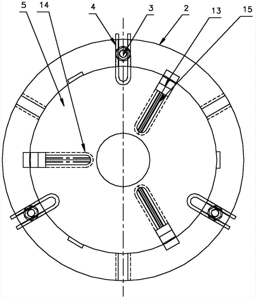
A kind of frock of rapid-mounted of gear shapping machine processing gear ring; Comprise pallet; And radially extend to six cushion block group locating slots that the pallet center is uniformly distributed with along the pallet circumference, and being the cushion block group that is intervally distributed with along its cushion block group locating slot slip in six cushion block group locating slots, the cushion block group is provided with the pull bar group; Said pallet top is provided with scroll chuck, and scroll chuck is fixed through three pull bar groups on the said pallet; Said scroll chuck is the disc-shaped structure that through hole is established at the center; Be provided with three along through hole to disc circumference and be the chuck jaw locating slot that hexagonal angle distributes each other; Along being provided with the chuck locator card in the chuck jaw locating slot, on the chuck locator card, be connected with the chuck jaw that slides synchronously along the chuck jaw locating slot.
The utility model is further characterized in that:
The rotation of said pull bar group along cushion block group axle center, and the pull bar group is the U type structure of an end opening.
The rapid-mounted frock of this gear shapping machine processing gear ring has following characteristics:
1) use waste and old lathe parts---scroll chuck constitutes with trays, and it is simple in structure, handled easily, can be fast that workpiece installation, centering is good.
2) improved that the different parts of every dress all need be with garden inside and outside the workpiece and end face centering in the original processing; The defective that centering speed is slow, time-consuming; Improve the back and use the lathe scroll chuck, only need the scroll chuck centering is got final product, when refilling workpiece (gear ring); Through the self-centering of scroll chuck, just can gear ring be tightened, centering.Fixed gear ring easily tightens gear ring rapidly.
3) gear ring that is suitable for various diameters is processed, and for batch spare, raising is installed, centering speed, and minimizing is installed, the centering time, has alleviated working strength of workers, has improved operating efficiency, has reduced cost.
Description of drawings
Fig. 1 is the original tool structure sketch map that is installed of the utility model;
Fig. 2 is the tool structure sketch map that is installed after the utility model improves;
Fig. 3 is the utilization structure sketch map of the utility model;
Fig. 4 is the operation chart of the embodiment of the utility model;
Among the figure: 1, workpiece, 2, pallet, 3, the cushion block group, 4, the pull bar group, 5, scroll chuck; 6, pinion cutter, 7, locking nut, 8, knife bar, 9, the slide plate knife rest, 10, column; 11, lathe bed, 12, workbench, 13, chuck jaw, 14, the chuck jaw locating slot, 15, the chuck locator card.
The specific embodiment
Below in conjunction with the accompanying drawing and the specific embodiment the utility model is elaborated.
As shown in Figure 2, be the tool structure sketch map that is installed after the utility model improves.Originally the frock that is installed comprises pallet 2; And radially extend to six cushion block group locating slots that pallet 2 centers are uniformly distributed with along pallet 2 circumference; In six cushion block group locating slots, wherein three are provided with the cushion block group 3 that can slide along this locating slot respectively in the cushion block group locating slot of space, and cushion block group 3 is provided with pull bar group 4; Pull bar group 4 can be rotated along cushion block group 3 axle center, and pull bar group 4 is the U type structure of an end opening.Pallet 2 is provided with scroll chuck 5, and scroll chuck 5 is fixing through three pull bar groups 4.Scroll chuck 5 is established the disc-shaped structure of through hole for the center; Be provided with three along through hole to disc circumference and be the chuck jaw locating slot 14 that hexagonal angle distributes each other; Be provided with a chuck jaw 13 at each three chuck jaw locating slot 14 port; Along being provided with chuck locator card 15 in the chuck jaw locating slot 14, each chuck jaw 13 can slide along chuck jaw locating slot 14 under the rotation of chuck locator card 15 synchronously.
As shown in Figure 3, be the utilization structure sketch map of the utility model; Through directly workpiece 1 being installed of scroll chuck 5; Any one of (being mutually 120 angles) three positions; Can fast workpiece 1 gear ring be fixed on the scroll chuck 5, and workpiece 1 contacts with at the bottom of scroll chuck 5 cards fully, guaranteed the stability that the workpiece gear ring is installed.
The self-centering function of the utility model through scroll chuck 5 behind the three-jaw centering, directly fastens and is fixed on the pallet.The waste and old scroll chuck of the frock that originally is installed lathe capable of using directly tightens workpiece with scroll chuck, through rechecking workpiece, can satisfy the centering of workpiece basically, satisfies required precision.Adopt scroll chuck, fixation workpiece is easy and simple to handle, quick rapidly.And accomplished the utilization again of waste product.
As shown in Figure 4, be the operation chart at gear shapping machine processing gear ring embodiment of the utility model.Lathe bed 11 is provided with column 10, in column 10 top-side slide plate knife rest 9 is set, and slide plate knife rest 9 belows are provided with the pinion cutter 6 that connects through knife bar 8, and pinion cutter 6 is connected with knife bar 8 through locking nut 7.In addition lathe bed 11 horizontal planes are provided with workbench 12, are placed with the utility model that comprises pallet 2, scroll chuck 5 frock that is installed at workbench 12.During gear shaping workpiece 1 gear ring level is installed on the scroll chuck 5; Scroll chuck 5 closely is connected with pallet 2 through pull bar group 4, cushion block group 3, and pallet 2 closes with 12 of workbench, and workbench 12 is consistent with workpiece 1 motion like this; Pinion cutter 6 pumps with knife bar 8; Workpiece 1 carries out gyration and cutter relieving motion with workbench 12, carries out resultant motion clocklike by change gear and transmission system, processes each tooth of workpiece gear ring.The effect of scroll chuck 5 is exactly workpiece 1 gear ring that pallet on the workbench passes to chucking in the scroll chuck 5 like clockwork that moves through with workbench; Workbench rotatablely moves when work and adds the cutter relieving motion; The gripper chuck clamping of workpieces guarantees that workpiece is consistent with working table movement.Satisfy the processing request of workpiece gear ring.
Because prototype structure, be installed, more time-consuming, the effort of workpiece during centering, and increased scroll chuck after improving, can fast, easily gear ring be installed on the scroll chuck, to move with pallet and workbench, installation accuracy is high, satisfies processing.
The utility model is simple in structure, and cost low (utilizing waste and old equipment) is installed, easy to use, can the different blowout patche of installation dimension, and fitting limit is big, can satisfy the processing that is used for various different size gear rings.Reduce the time that installation, centering are installed, improved the working (machining) efficiency of gear shapping machine widely, alleviated working strength of workers.
The above; Be merely the preferable specific embodiment of the utility model; But the protection domain of the utility model is not limited thereto; Any technical staff who is familiar with the present technique field is in the technical scope that the utility model discloses, and the variation that can expect easily or replacement all should be encompassed within the protection domain of the utility model.

Claims (2)

1. the frock of the rapid-mounted of a gear shapping machine processing gear ring; Comprise pallet (2); And radially extend to six cushion block group locating slots that pallet (2) center is uniformly distributed with along pallet (2) circumference, and being the cushion block group (3) that is intervally distributed with along its cushion block group locating slot slip in six cushion block group locating slots, cushion block group (3) is provided with pull bar group (4); It is characterized in that: said pallet (2) top is provided with scroll chuck (5), and scroll chuck (5) is fixing through three the pull bar groups (4) on the said pallet (2); Said scroll chuck (5) is established the disc-shaped structure of through hole for the center; Be provided with three along through hole to disc circumference and be the chuck jaw locating slot (14) that hexagonal angle distributes each other; Along being provided with chuck locator card (15) in the chuck jaw locating slot (14), on chuck locator card (15), be connected with the chuck jaw (13) that slides synchronously along chuck jaw locating slot (14).
2. the frock of the rapid-mounted of a kind of gear shapping machine processing gear ring according to claim 1 is characterized in that: said pull bar group (4) rotation along cushion block group (3) axle center, and pull bar group (4) is the U type structure of an end opening.
CN 201220023616 2012-01-18 2012-01-18 Tool for fast clamping processed gear rings of gear shaping machine Expired - Fee Related CN202490987U (en)

Priority Applications (1)

Application Number Priority Date Filing Date Title
CN 201220023616 CN202490987U (en) 2012-01-18 2012-01-18 Tool for fast clamping processed gear rings of gear shaping machine

Applications Claiming Priority (1)

Application Number Priority Date Filing Date Title
CN 201220023616 CN202490987U (en) 2012-01-18 2012-01-18 Tool for fast clamping processed gear rings of gear shaping machine

Publications (1)

Publication Number Publication Date
CN202490987U true CN202490987U (en) 2012-10-17

Family

ID=46997230

Family Applications (1)

Application Number Title Priority Date Filing Date
CN 201220023616 Expired - Fee Related CN202490987U (en) 2012-01-18 2012-01-18 Tool for fast clamping processed gear rings of gear shaping machine

Country Status (1)

Country Link
CN (1) CN202490987U (en)

Cited By (8)

* Cited by examiner, † Cited by third party
Publication number Priority date Publication date Assignee Title
CN102896379A (en) * 2012-10-23 2013-01-30 常熟天地煤机装备有限公司 Universal hobbing device for shaft gear
CN103292673A (en) * 2013-05-29 2013-09-11 辽宁科技大学 Method and device for detecting wear of tooth surface of large involute spur gear
CN105171864A (en) * 2015-09-17 2015-12-23 怀宁县明慧竹业有限公司 Automatic punching machine for steamer
CN105252086A (en) * 2015-12-03 2016-01-20 重庆望江工业有限公司 Gear grinding clamping device of planetary gear of wind power generation device
CN105328280A (en) * 2015-11-30 2016-02-17 重庆市首业机械制造有限公司 Clamping tool provided with lead screw and restoring compression springs
CN106181504A (en) * 2016-08-31 2016-12-07 青岛海之冠汽车配件制造有限公司 A kind of gear ring fixing device of hole machined in gear ring
CN106735616A (en) * 2016-12-25 2017-05-31 重庆润跃机械有限公司 Gear gear shaping clamping device
CN111390297A (en) * 2020-04-18 2020-07-10 无锡易通精密机械股份有限公司 Copying cutting equipment and machining process for bearing gear ring insection

Cited By (12)

* Cited by examiner, † Cited by third party
Publication number Priority date Publication date Assignee Title
CN102896379A (en) * 2012-10-23 2013-01-30 常熟天地煤机装备有限公司 Universal hobbing device for shaft gear
CN103292673A (en) * 2013-05-29 2013-09-11 辽宁科技大学 Method and device for detecting wear of tooth surface of large involute spur gear
CN103292673B (en) * 2013-05-29 2015-10-21 辽宁科技大学 Involute spur large gear tooth surface abrasion detection method and device thereof
CN105171864A (en) * 2015-09-17 2015-12-23 怀宁县明慧竹业有限公司 Automatic punching machine for steamer
CN105328280A (en) * 2015-11-30 2016-02-17 重庆市首业机械制造有限公司 Clamping tool provided with lead screw and restoring compression springs
CN105252086A (en) * 2015-12-03 2016-01-20 重庆望江工业有限公司 Gear grinding clamping device of planetary gear of wind power generation device
CN106181504A (en) * 2016-08-31 2016-12-07 青岛海之冠汽车配件制造有限公司 A kind of gear ring fixing device of hole machined in gear ring
CN106181504B (en) * 2016-08-31 2018-09-28 青岛海之冠汽车配件制造有限公司 A kind of gear ring fixing device for hole machined in gear ring
CN106735616A (en) * 2016-12-25 2017-05-31 重庆润跃机械有限公司 Gear gear shaping clamping device
CN106735616B (en) * 2016-12-25 2019-01-22 重庆润跃机械有限公司 Gear gear shaping clamping device
CN111390297A (en) * 2020-04-18 2020-07-10 无锡易通精密机械股份有限公司 Copying cutting equipment and machining process for bearing gear ring insection
CN111390297B (en) * 2020-04-18 2024-03-26 无锡易通精密机械股份有限公司 Copying cutting equipment and machining process for gear ring insection of bearing

Similar Documents

Publication Publication Date Title
CN202490987U (en) Tool for fast clamping processed gear rings of gear shaping machine
CN102294498B (en) Clamping jaw linked adjusting wheel hub chuck
CN201030488Y (en) Clamp for processing spacing angle plane
CN202317655U (en) Six-station disc processing machine
CN202388274U (en) Rotation station turning tool for four-circuit protection valve
CN102152145A (en) Clamp device for processing brake cylinder of high-speed rail train
CN203610964U (en) Turning and milling composite machine tool
CN204019206U (en) A kind of five degree of freedom bench vice
CN103801912A (en) Method for machining gas compressor fixed blade ring of gas turbine
CN103909282A (en) Balance adjustable lathe fixture
CN204234843U (en) The continuous multiaspect milling device of a kind of CNC milling machine
CN105108536A (en) Multiple workpiece processing clamp
CN204747544U (en) Movable jack catch clamping mechanism
CN204321653U (en) A kind of automotive brake four station turning tool
CN104175150A (en) Pressure casting transformed special-shaped product hole positioning pneumatic clamp and clamping method
CN203579264U (en) Combined clamp for shaft sleeve hole finishing
CN202239722U (en) Clamping jaw linked adjusting hub chuck
CN205020975U (en) Thin wall ring gear class part gear shaping anchor clamps
CN203875687U (en) Auxiliary machining device of horizontal three-axis numerical control machining center
CN203765056U (en) Simple milling device of symmetrical key groove
CN204471040U (en) The Four-axis milling fixture of a kind of automobile steering device long shell two stomidium and cross-drilled hole
CN103753155B (en) A kind of hydraulic turbine annular piston processing technology and machining tool thereof
CN206356927U (en) Bearing bridge double plate jig
CN208592594U (en) One kind can self-centering pneumatic rotary workbench
CN204321689U (en) The chucking device of tube sheet processing

Legal Events

Date Code Title Description
C14 Grant of patent or utility model
GR01 Patent grant
C17 Cessation of patent right
CF01 Termination of patent right due to non-payment of annual fee

Granted publication date: 20121017

Termination date: 20140118