CN202490983U - Grinding hob for asymmetric tooth profile involute gear - Google Patents
Grinding hob for asymmetric tooth profile involute gear Download PDFInfo
- Publication number
- CN202490983U CN202490983U CN2012201028443U CN201220102844U CN202490983U CN 202490983 U CN202490983 U CN 202490983U CN 2012201028443 U CN2012201028443 U CN 2012201028443U CN 201220102844 U CN201220102844 U CN 201220102844U CN 202490983 U CN202490983 U CN 202490983U
- Authority
- CN
- China
- Prior art keywords
- working side
- gear
- cutter
- flank profil
- working
- Prior art date
- Legal status (The legal status is an assumption and is not a legal conclusion. Google has not performed a legal analysis and makes no representation as to the accuracy of the status listed.)
- Expired - Fee Related
Links
- 238000005520 cutting process Methods 0.000 claims description 37
- 238000003754 machining Methods 0.000 claims description 14
- 238000012545 processing Methods 0.000 abstract description 36
- 238000000034 method Methods 0.000 abstract description 17
- 230000008569 process Effects 0.000 abstract description 10
- 230000007704 transition Effects 0.000 abstract description 5
- 238000013461 design Methods 0.000 description 20
- 238000012986 modification Methods 0.000 description 19
- 230000004048 modification Effects 0.000 description 19
- 241000271460 Crotalus cerastes Species 0.000 description 7
- 238000005452 bending Methods 0.000 description 4
- 238000012937 correction Methods 0.000 description 4
- 238000005096 rolling process Methods 0.000 description 3
- 238000012938 design process Methods 0.000 description 2
- 238000010438 heat treatment Methods 0.000 description 2
- 238000005259 measurement Methods 0.000 description 2
- 229910052757 nitrogen Inorganic materials 0.000 description 2
- 229910052698 phosphorus Inorganic materials 0.000 description 2
- RYGMFSIKBFXOCR-UHFFFAOYSA-N Copper Chemical compound [Cu] RYGMFSIKBFXOCR-UHFFFAOYSA-N 0.000 description 1
- 230000002337 anti-port Effects 0.000 description 1
- 238000013459 approach Methods 0.000 description 1
- 230000009286 beneficial effect Effects 0.000 description 1
- 230000002457 bidirectional effect Effects 0.000 description 1
- 230000015572 biosynthetic process Effects 0.000 description 1
- 238000004364 calculation method Methods 0.000 description 1
- 238000005255 carburizing Methods 0.000 description 1
- 230000008859 change Effects 0.000 description 1
- 230000019771 cognition Effects 0.000 description 1
- 230000006835 compression Effects 0.000 description 1
- 238000007906 compression Methods 0.000 description 1
- 239000012141 concentrate Substances 0.000 description 1
- 229910052802 copper Inorganic materials 0.000 description 1
- 239000010949 copper Substances 0.000 description 1
- 238000010586 diagram Methods 0.000 description 1
- 230000000694 effects Effects 0.000 description 1
- 238000005516 engineering process Methods 0.000 description 1
- 239000012467 final product Substances 0.000 description 1
- 238000004519 manufacturing process Methods 0.000 description 1
- 238000013507 mapping Methods 0.000 description 1
- 238000000465 moulding Methods 0.000 description 1
- 239000000843 powder Substances 0.000 description 1
- 239000000047 product Substances 0.000 description 1
- 238000010791 quenching Methods 0.000 description 1
- 230000000171 quenching effect Effects 0.000 description 1
- 238000011160 research Methods 0.000 description 1
- 230000008719 thickening Effects 0.000 description 1
- 230000009466 transformation Effects 0.000 description 1
- 239000002699 waste material Substances 0.000 description 1
Images

Landscapes
- Gear Processing (AREA)
Abstract
The utility model provides a grinding hob for an asymmetric tooth profile involute gear. The normal tooth profile of the grinding hob is an asymmetric rack tooth profile; a working side tooth profile comprises a working side main blade, a working side cutter tooth tip arc and a working side transition blade; the working side main blade is used for generating a gear working side involute through enveloping in the processing process; the working side cutter tooth tip arc is used for generating a gear working side tooth root arc in the processing process; the working side transition blade is arranged between the working side main blade and the working side cutter tooth tip arc; a non-working side tooth profile comprises a non-working side main blade, a non-working side cutter tooth tip arc and a non-working side transition blade; the non-working side main blade is used for generating a gear non-working side involute through enveloping in the processing process; the non-working side cutter tooth tip arc is used for generating a gear non-working side tooth root arc in the processing process; the non-working side transition blade is arranged between the non-working side main blade and the non-working side cutter tooth tip arc; a pressure angle of the working side main blade is in a range of 14-40 degrees; and the pressure angle of the working side main blade is 6-18 degrees larger than that of the non-working side main blade. The hob can be used for processing an asymmetric tooth profile involute gear.
Description
Technical field
The utility model relates to a kind of gear and stays the mill hobboing cutter, relates in particular to a kind of asymmetric flank profil involute gear and stays the mill hobboing cutter, belongs to the cutter for gear wheel technical field.
Background technology
The flank profil of the gear teeth both sides of tradition involute gear is symmetrical fully, and basic parameter has pressure angle, addendum coefficient, tip clearance coefficient, outside circle ascent etc.For the unification of cutter, the standard of all working out the involute gear basic rack tooth profile both at home and abroad.Like ha-height of teeth top, ha=han*m, wherein: m-modulus is a normal module to helical gear; Han*-addendum coefficient.
For most gears, the load during rotating is different, the just single direction running that has, though what have is bidirectional movement, the time of antiport and load are all much lower than forward.The tooth Profile Design of complete symmetry causes main supporting surface because parameter limit makes performance be restricted, and reverse side then causes waste because inapplicable, few use or underloading use.
In recent years, asymmetric flank profil involute gear steps into the application stage from research gradually.Publication number is that the Chinese utility model of CN201851630U promptly relates to a kind of asymmetric flank profil involute gear.Because asymmetric flank profil gear, is realized significantly improving and is improved the gear capacity effect to strengthen the approach of main stand under load side flank profil through the flank profil that weakens non-stand under load or receive the underloading side, has very strong vitality and fabulous application prospect.
But, receive flank profil to shape the restriction of method, the application of present asymmetric flank profil involute gear mainly also is confined to adopt in the scope of mould molding gear, like plastic gear, cast gear, powder metallurgical gear and stamped gear etc.And the method that can adopt the asymmetric flank profil involute gear that machining produces is seldom, reported wired cutting gear, and this method receives the restriction of processing cost, efficient and precision, is difficult in each industrial circle and obtains to apply on a large scale.
On the other hand, the leading position that in the present stage gear product, occupied of the hardened face gear of carburizing and quenching roll flute.Because this gear is a roll flute just after heat treatment; Used hobboing cutter must be have an amount of uprooting necessarily stay mill hobboing cutter (also claiming plush copper hobboing cutter or pre-grinding hob); Handle stays the mill amount partly to grind off when roll flute; The flank profil that could guarantee to grind behind the roll flute can with need not grind the tooth root position camber line that yet should not grind and partly have and good excessively do not produce the roll flute step, do not hinder tooth root.Simultaneously; Concentrate in order to reduce stress; Guaranteeing that involute generation length can satisfy under the condition of gears engaged requirement, the radius of Gear Root position camber line (the partly conjugated generation of the fillet of tooth root position camber line and hobboing cutter cutter head) is the bigger the better, and promptly the fillet R of hobboing cutter cutter head is the bigger the better; This point, the hobboing cutter of the symmetrical flank profil gear of present many standards also fails to accomplish fully.
Strictly speaking; Involute gear stays the normal profile of mill hobboing cutter should comprise three parts: (its pressure angle equals the pressure angle of institute's Machining of Gear to major cutting edge; The involute that adds envelope generation in man-hour gear teeth both sides), the circular arc (adding the circular arc and the transition curve that generate the gear teeth tooth root man-hour) of hobboing cutter cutter head and excessively sword (its pressure angle adds the involute that envelope generation in the man-hour gear teeth stay mill amount terminal point to form less than the pressure angle of institute's Machining of Gear).Stay the mill hobboing cutter if design asymmetric flank profil involute gear, its normal profile will comprise above-mentioned three parts too, will satisfy the big as far as possible requirement of radius R of Gear Root position camber line too.
The utility model content
The purpose of the utility model is, overcomes the problem that exists in the prior art, proposes a kind of asymmetric flank profil involute gear and stays the mill hobboing cutter, can process asymmetric flank profil involute gear.
For solving above technical problem; A kind of asymmetric flank profil involute gear that the utility model provided stays the mill hobboing cutter; The normal profile of said hobboing cutter is the asymmetric spline flank profil, wherein the active side flank profil comprise add man-hour envelope generate gear teeth active side involute the active side major cutting edge, add the active side cutter teeth tip circle arc that generates the gear teeth active side tooth root position camber line man-hour and the active side transitional edges between said active side major cutting edge and said active side cutter teeth tip circle arc; Wherein the non-working side flank profil comprise add man-hour envelope generate gear teeth non-working side involute the non-working side major cutting edge, add the non-working side cutter teeth tip circle arc that generates the gear teeth non-working side tooth root position camber line man-hour and the non-working side transitional edges between said non-working side major cutting edge and said non-working side cutter teeth tip circle arc; The pressure angle scope of said active side major cutting edge is 14 °~40 °, and the pressure angle of said active side major cutting edge than the pressure angle of said non-working side major cutting edge big 6 °~18 °.
With respect to prior art; The utility model has been obtained following beneficial effect: this hobboing cutter can gear hobbing process asymmetric flank profil involute gear; Wherein active side major cutting edge and non-working side major cutting edge can corresponding cut out the active side involute and the non-working side involute of the gear teeth, and active side cutter teeth tip circle arc and non-working side cutter teeth tip circle arc can corresponding cut out the active side tooth root position camber line and the non-working side tooth root position camber line of the gear teeth; Adopt the hobboing cutter of this flank profil, can solve the gear hobbing processing of the asymmetric flank profil gear in 14 °~40 ° scopes in pressure at both sides angle, tooth root rounding off behind the realization roll flute.
As the preferred version of the utility model, the radius of said active side cutter teeth tip circle arc is greater than the radius of said non-working side cutter teeth tip circle arc.Can reach the R value of the standard symmetry flank profil hobboing cutter littler 10 °, the bending strength of the tooth root of raising institute Machining of Gear than its pressure angle.
As the preferred version of the utility model, the relation between the modulus m of the height of teeth top ha of said active side flank profil and non-working side flank profil and institute's Machining of Gear is 1.0 m≤ha≤1.45m.Institute's Machining of Gear can be long flank profil, also can be short flank profil.
As the preferred version of the utility model, said active side flank profil and said non-working side flank profil all leave the amount of uprooting.Can guarantee not to be ground to tooth root behind the roll flute.
As the another kind of preferred version of the utility model, the amount of uprooting of said active side flank profil and said non-working side flank profil is zero.The amount of uprooting is zero special case as the band amount of uprooting, the gear hobbing that can be used for not being with the asymmetric flank profil involute gear that stays the mill amount.
Description of drawings
Below in conjunction with accompanying drawing the utility model is further described.
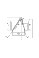
Fig. 1 stays the normal profile of mill hobboing cutter for the asymmetric flank profil involute gear of the utility model.
Among the figure: 1-active side major cutting edge, 2-active side transitional edges, 3-active side cutter teeth tip circle arc, 4-non-working side cutter teeth tip circle arc, 5-non-working side transitional edges, 6-non-working side major cutting edge, h
A0-cutter teeth is risen, the Δ-amount of uprooting, H-cutter teeth overall height, S
n-cutter center line transverse tooth thickness, α
g-active side pressure angle, R
g-active side cutter teeth tip circle arc radius, α
Gg-active side transitional edges pressure angle, h
AThe α of-active side Δ=0
gThe height of pressure linea angulata and cutter teeth tip circle angle point of contact A, R-cutter tooth fillet radius, α
f-non-working side pressure angle, R
f-non-working side cutter teeth tip circle arc radius, α
Fg-non-working side transitional edges pressure angle, h
AfThe α of-non-working side Δ=0
gThe height of pressure linea angulata and cutter teeth tip circle angle point of contact A.Annotate: this specification is an active side with the large pressure angle side, is non-working side with little pressure angle side.
Fig. 2 finds the solution reference diagram for asymmetric flank profil involute gear stays the normal profile of mill hobboing cutter.
Among the figure: the symbol identical with Fig. 1 repeats no more, and the symbol description that only Fig. 1 was not occurred is following:
A, A
fThe point of contact at-active side, non-working side pressure linea angulata and cutter teeth tip circle angle;
C, C
fThe point of contact at-active side, non-working side transitional edges and cutter teeth tip circle angle;
B, B
fThe intersection point of-active side, non-working side major cutting edge and transitional edges, h
B, h
Bf-be corresponding height;
Δ
0π m on the-cutter center line
n/ 2 points (no sideshake transverse tooth thickness) are to the distance of major cutting edge Δ direction;
Δ
1-transverse tooth thickness the upper deviation is to the distance of major cutting edge in the Δ direction, S, S
fThe intersection point of-active side, non-working side transverse tooth thickness upper deviation line and excessive sword, h
S, h
Sf-be S, S
fThe corresponding height of point, this point promptly are the points of the starting point of involute when determining roll flute to be ground to the transverse tooth thickness upper deviation.If the starting point of involute can satisfy the gears engaged requirement when roll flute was ground to the transverse tooth thickness upper deviation; Just all can satisfy gear when then roll flute is ground to other position and can mesh requirement (starting point of involute just more can satisfy the gear meshing requirement during transverse tooth thickness lower deviation); So except that special demands, generally only obtain S, S during Tool Design
fPoint and corresponding height get final product.
Other Points And lines is to find the solution the boost line of mapping and the point of generation among the figure, will explain in an embodiment, repeats no more here.
Fig. 3 is an asymmetric external gear teeth portion major parameter sketch map.
Among the figure: d
j-sharp circular diameter, d
a-tip diameter, d-reference diameter, d
Bg, d
B fThe base circle diameter (BCD) of-working gear the flank of tooth, non-working flank;
α
Jg, α
Jf-working flank, non-working flank wedge angle, S-graduated arc thickness;
E
g, E
f-working flank, the non-working flank starting point of meshing, d
Eg, d
E f-working gear the flank of tooth, non-working flank mesh initial circular diameter;
F
g, F
fThe involute starting point that-working flank, non-working flank processing generate, d
Fg, d
F fThe initial circular diameter of the involute that-working gear flank of tooth, non-working flank processing generate.
The specific embodiment
As shown in Figure 1; The asymmetric flank profil involute gear of the utility model stays the mill hobboing cutter; The normal profile of hobboing cutter is the asymmetric spline flank profil, wherein the active side flank profil comprise add man-hour envelope generate gear teeth active side involute active side major cutting edge 1, add the active side cutter teeth tip circle arc 3 that generates the gear teeth active side tooth root position camber line man-hour and the active side transitional edges 2 between active side major cutting edge 1 and active side cutter teeth tip circle arc 3; Wherein the non-working side flank profil comprise add man-hour envelope generate gear teeth non-working side involute non-working side major cutting edge 6, add the non-working side cutter teeth tip circle arc 4 that generates the gear teeth non-working side tooth root position camber line man-hour and the non-working side transitional edges 5 between non-working side major cutting edge 6 and non-working side cutter teeth tip circle arc 4; The pressure angle scope of active side major cutting edge 1 is 14 °~40 °, and the pressure angle of active side major cutting edge 1 than the pressure angle of non-working side major cutting edge 6 big 6 °~18 °.
Relation between the modulus m of the height of teeth top ha of active side flank profil and non-working side flank profil and institute's Machining of Gear is 1.0 m≤ha≤1.45m.Institute's Machining of Gear can be long flank profil, also can be short flank profil.
Active side flank profil and non-working side flank profil all leave the amount of uprooting, and can guarantee not to be ground to tooth root behind the roll flute.The amount of uprooting is zero special case as the band amount of uprooting, the gear hobbing that can be used for not being with the asymmetric flank profil involute gear that stays the mill amount.
Design sequence is with reference to figure 2, Fig. 3:
1, confirm the height of teeth top h of cutter according to gear parameter
A0, calculate the active side of two-wheeled and the initial circular diameter d of engagement of non-working side
Eg, d
Ef, final processing generates the initial round d of involute
Fg, d
FfMust meet the demands.
2, confirm that the amount of uprooting Δ, base tangent length stay mill amount Δ W, π m
n/ 2 position (Δs with respect to cutter
0Amount).The value of both sides should be identical.
3, press π M
n/ 2, add (Δ-Δ
0)/cos α
g(Δ-Δ
0)/cos α
fBe the center line bottom side length, with (90-α
g), (90-α
f) be that triangle is made at two base angles, get three summit I, II, III.Cross the summit I and make the vertical line on base.Obtain the length of side on other both sides with sine.
4, with the height of teeth top h of cutter
A0Make the parallel lines of base II-III for height, hand over the triangle both sides in P, N point respectively, the P point of excessive pressure angle side is made angular bisector P-O of ∠ APN
1
5, just decide large pressure angle and sidewinder cutter tooth tip circle arc radius R
gMaximum, with h
A0-R
gFor height is made another parallel lines of base II-III, with angular bisector P-O of ∠ APN
1Meet at O
1Point is crossed O
1The vertical line intersection section P-N that does the base is in the M point.With O
1Point is that the center of circle is with MO
1For radius is made circular arc and large pressure angle limit I-II is cut in the A point.The M point is the peak of cutter tooth top.
6, cross angular bisector N-O that the N point is made ∠ PN III
2Intersection section M-O
1In O
2Point is with O
2Point is that the center of circle is with MO
2For radius is made circular arc and limit I-III is cut in A
fPoint, then MO
2For little pressure angle sidewinders cutter tooth tip circle arc radius R
fMaximum.
7, the excessive sword pressure angle in given both sides is made the excessive sword tangent line of both sides hobboing cutter tooth top circular arc respectively.Judge that large and small pressure angle sidewinders cutter tooth tip circle arc R
gAnd R
fCan meet the demands, (S and S on the excessive sword of cutter during by transverse tooth thickness upper deviation roll flute
fThe initial circle of the involute of dot generation) can satisfy the engagement requirement, if can not meet the demands, the height of teeth top h of then available adjustment cutter
A0Or reduce large pressure angle and sidewinder cutter tooth tip circle arc R
gThe way of value designs again.
8, make the major cutting edge line, calculate the height of major cutting edge and excessive sword intersection point.Calculate the transverse tooth thickness of cutter center line.
9; When the modification coefficient of the unsymmetric gear both sides that processed not simultaneously; Way with revising a side tool tool transverse tooth thickness designs cutter; Make when reaching the modification coefficient Machining of Gear by non-correction side gear, revise the flank of tooth that the side tool sword processes and be exactly the flank of tooth that the modification coefficient by original design processes.Revise the major cutting edge of this side by the cutter transverse tooth thickness of revising a side, and recomputate the change in size that causes because of correction.
10, confirm inside pitch line length and root fillet equidimension, accomplish tooth Profile Design.
Existing with a pair of M of Design and Machining
nThe unsymmetric gear of=10mm is an example, and specifying respectively, the unsymmetric gear of the big pinion of Design and Machining stays the method for grinding hobboing cutter.
Embodiment one
The unsymmetric gear parameter is (with reference to figure 3) as follows:
The pinion number of teeth 21, the gear wheel number of teeth 92; Active side pressure angle α
g=34 °, non-working side pressure angle α
f=16 °; 13.8 ° of helical angles, centre-to-centre spacing 585.5mm; Bottom clearance C
n *=0.25;
Pinion gear teeth outside diameter circle d
A1=243.0mm, reference diameter d
1=216.242mm, active side modification coefficient x
G1=0.3187, non-working side modification coefficient x
F1=0.3187, sharp circular diameter d
J1=247.549mm, active side wedge angle α
Jg=44.15524 °, non-working side wedge angle α
Jf=33.0941 °, active side meshes initial circular diameter d
g=201.795 mm, non-working side mesh initial circular diameter d
f=207.751mm; Base tangent length W when striding the measurement of 3 teeth
3=81.405mm, the upper deviation-0.089mm, lower deviation-0.136mm;
Gear wheel tip diameter d
A2=971.0mm, reference diameter d
2=947.346mm, active side modification coefficient x
G2=0.0543, non-working side modification coefficient x
F2=0.0651, sharp circular diameter d
J2=978.886mm, active side wedge angle α
Jg=37.3577 °, non-working side wedge angle α
Jf=21.84952 °, active side meshes initial circular diameter d
E2g=930.788 mm, non-working side mesh initial circular diameter d
E2f=936.776mm; Base tangent length W when striding the measurement of 10 teeth
10=304.615mm, the upper deviation-0.164mm, lower deviation-0.24mm;
Design is (with reference to figure 2) according to the following steps:
The cutter of processing large and small gear will design respectively.
The cutter of Design and Machining pinion:
1, confirm the height of teeth top h of cutter by the method for designing of universal cutter according to gear parameter
A0=13.808mm gets h
A0=14.00mm.
Calculate the active side of gear and the initial circular diameter of engagement of non-working side, active side d
g=201.795mm, non-working side mesh initial circular diameter d
f=207.751mm; , final processing generates the initial round d of involute
F1 g, d
F1 fMust meet the demands.
2, get the amount of uprooting Δ=0.35mm, Δ
0=0.222mm, then Δ
1=0.222+ base tangent length the upper deviation 0.089/2=0.2665mm, Δ-Δ
0=0.35-0.222=0.128 mm, base tangent length is stayed mill amount Δ W=0.58mm, and the value of both sides is identical.
Stay the mill hobboing cutter amount of uprooting and stay the value principle of mill amount to be: the amount of uprooting of hobboing cutter of rolling pinion is little, and the amount of uprooting of hobboing cutter of rolling gear wheel is big; That rolls pinion stays the mill amount big, roll gear wheel stay the mill amount little.Δ
0Then determine by Δ W.Because the numerical value of this tittle does not have unified standard at home as yet, understanding and cognition is variant, the actual relatively confusion of carrying out.Just different such as the understanding of base tangent length being stayed the mill amount, often cause between manufacturing and use to have certain deviation.The mill amount of staying of present embodiment is to calculate by the middle difference of base tangent length.Therefore, the amount of uprooting mainly is based on gear parameter with the concrete numerical value that stays the mill amount and heat treated control level is confirmed by design experiences, is the rule of staying the mill hob design.
3, press L
The II III=π Mn/2+ (Δ-Δ
0)/cos α
g+ (Δ-Δ
0)/cos α
f=π * 10/2+0.128/cos34 °+0.128/cos16 °=15.9956mm is the center line bottom side length, with (90-α
g)=90-34=56 °, (90-α
f)=90-16=74 ° is that triangle is made at two base angles, gets three summit I, II, III.Cross the summit I and make the vertical line on base,
Obtain the length of side L on other both sides with sine
The I II=20.0718mm, L
The I III=17.3109mm.Triangle form height h
I=16.6403mm.
4, with the height of teeth top h of cutter
A0=14mm is the parallel lines that height is made base II-III, hands over both sides in P, N point respectively, and the P point of excessive pressure angle side is made angular bisector P-O of ∠ APN
1
5, just decide large pressure angle and sidewinder cutter tooth tip circle arc R
gMaximum R
g=3mm; , with h
A0-R
g=14-3=11mm is another parallel lines that height is made base II-III, meets at P point and N point respectively with both sides, with angular bisector P-O of ∠ APN
1Meet at O
1, cross O
1The vertical line intersection section P-N that does the base is in the M point.With O
1Point is that the center of circle is with MO
1=3mm is that radius is made circular arc and large pressure angle limit I-II is cut in the A point.The M point is the peak of cutter tooth top.
∠APO
1=∠MPO
1=(180-56)/2?=62°,
Line segment L
PN=(h
I-h
A0)/h
I* L
The II III=(16.6403-14)/16.6403 * 15.9956=2.538mm,
L
PM?=?L
MO1×tan(∠PO
1M)=3×tan(90-62)=1.5951mm,
L
MN?=?L
PN-L
PM?=2.538-1.5951=0.9429mm
6, cross angular bisector N-O that the N point is made ∠ PN III
2Intersection section M-O
1In O
2Point is with O
2Point is that the center of circle is with MO
2For radius is made circular arc and limit I-III is cut in A
fPoint, then line segment MO
2Length be exactly that little pressure angle sidewinders cutter tooth tip circle arc radius R
fMaximum.
∠MNO
2=∠A
fNO
2=(180-74)/2=53°,
L
MO2=?L
MN×tan(∠MNO
2)=?0.9429×tan53°=1.251mm,
R
f?=?L
MO2=1.251mm。Because this side is a non-working surface, the power that root fillet partly receives is compression, and R is slightly little can obviously not to influence teeth bending strength, R
fCan meet the demands.
7, the excessive sword pressure angle of given large pressure angle side α
G g=15 °, the excessive sword pressure angle of little pressure angle side α
F g=8 °, make the excessive sword tangent line of both sides hobboing cutter tooth top circular arc respectively, by the upper deviation (Δ of base tangent length
1=0.2665 mm) makes the parallel lines on both sides, meet at S and S with the excessive sword in both sides respectively
fPoint calculates 2 height to the cutter center line by correlation formula:
h
s?=12.05mm,?h
sf?=?12.499mm。
Promptly is the initial circle of resulting involute during by upper deviation roll flute with the be meshed starting point of meshing circle of gained of two lateral tooth flanks of this gear with this height value respectively as the height of teeth top of tooth bar, and its diameter is respectively:
Large pressure angle side d
F1 g=200.03mm<d
g=201.795mm,
Little pressure angle side d
F1f=207.40mm<d
f=207.751mm;
After adopting this parameter hobboing cutter gear hobbing, even by upper deviation roll flute, the involute starting point that is generated also can satisfy gears engaged and require (by other deviation roll flute, can satisfy gears engaged and require).
If can not meet the demands, the height of teeth top ha0 of then available adjustment cutter or reduce large pressure angle and sidewinder cutter tooth tip circle arc R
gThe way of value designs again.
8, make the major cutting edge line, calculate major cutting edge and excessive sword intersection points B and B
fThe height of point,
h
B=?11.223mm,?h
Bf=?10.519mm。
A and A
fThe height of point, h
A=12.678mm, h
Af=13.094mm.
Calculate cutter center line transverse tooth thickness (length between the major cutting edge of both sides)
S=?L
ⅡⅢ-Δ/cosα
g?-Δ/cosα
f?=?15.9956-0.35/cos34°-0.35/cos16°=15.209mm
9, because the modification coefficient of the both sides of this pinion is identical, both sides can be rolled into size simultaneously during gear hobbing, need not design cutter with the way of the cutter transverse tooth thickness of revising a side.
10, through calculating, process the flank profil at the outside circle place, both sides of this gear, needing the tooth root effective depth of cutter respectively is factors such as 8.93mm and 6.07mm, the surplus of consideration and root fillet, gets fully teeth height H=2.6m
n=26mm, cutter root fillet R==0.15m
n=1.5mm accomplishes the hobboing cutter tooth Profile Design.
The cutter of processing gear wheel is basic identical with the design sequence and the method for the cutter of processing pinion, several distinctive points:
1, as previously mentioned, the amount of uprooting of the cutter of processing gear wheel is bigger than the amount of the cutter of processing pinion, stays the mill amount littler than the amount of the cutter of processing pinion.Because the initial circular diameter of the involute of gear wheel guarantees more easily,, the radius at tooth tip of the cutter of processing gear wheel obtains greatly so can processing the value of the cutter of pinion frequently.
2; The modification coefficient of the gear wheel both sides of present embodiment is different; Must design cutter with the way of the cutter transverse tooth thickness of revising a side; Make when reaching the modification coefficient Machining of Gear by non-correction side gear, revise the flank of tooth that the side tool sword processes and be exactly the flank of tooth that the modification coefficient by original design processes.Revise the major cutting edge of this side by the cutter transverse tooth thickness of revising a side, and recomputate the value after relevant parameter changes.
Gear wheel hobboing cutter result of calculation is following:
1, the height of teeth top h of cutter
A0=14.00 mm
The active side of gear and the initial circular diameter of the engagement of non-working side, active side d
g=930.788mm, non-working side mesh initial circular diameter d
f=936.776mm.
The amount of uprooting Δ=0.5mm, Δ
0=0.105mm, then Δ-Δ
0=0.395mm, Δ
1=0.187mm, Δ W=0.45mm, the value of both sides is identical.
Hobboing cutter tooth top arc radius, large pressure angle side R
g=3.6mm; , little pressure angle side R
f=1.624mm.
Excessive sword pressure angle, large pressure angle side α
G g=15 °, little pressure angle side α
F g=8 °,
S and S
fThe height of point: h
s=10.993mm, h
Sf=10.67mm.
The initial circular diameter of involute is respectively:
Large pressure angle side d
F1 g=926.628mm<d
g=930.778mm,
Little pressure angle side d
F1f=928.594mm<d
f=936.776mm;
The involute starting point can satisfy the gears engaged requirement.
A and A
fThe height of point, h
A=12.413mm, h
Af=12.824mm.
B and B
fThe height of point, h
B=10.430mm, h
Bf=9.157mm.
Cutter center line transverse tooth thickness S=15.472mm
Fully teeth height H=2.6m
n=26mm, cutter root fillet R==0.15m
n=1.5mm.
2, to the correction of cutter transverse tooth thickness
Working gear side modification coefficient x
G2=0.0543, non-working side modification coefficient x
F2=0.0651.
Non-working side is than the big Δ x=x of active side modification coefficient
F2-x
G2=0.0651-0.0543=0.0108,
Radially to lack the degree of depth of rolling than active side be Δ h=Δ xm to non-working side during gear hobbing
n=0.0108 * 10=0.108mm.
If gear is pressed non-working side modification coefficient x
F2=0.0651 processing, after then the processing of the non-working side flank of tooth put in place, cutter also wanted secondary feed Δ h=0.108mm to put the processing of the active side flank of tooth in place; For fear of secondary feed again, can be to the transverse tooth thickness thickening Δ S of work side tool
g=Δ h2tan α
g=0.108 * 2 * tan34 °=0.1457 mm.
Also can be by working gear side modification coefficient x
G2=0.0543 processing, when then active side flank of tooth processing puts in place, the ultra dark feed of the non-working side flank of tooth Δ h=0.108mm, at this moment must be to the transverse tooth thickness attenuate Δ S of inoperative side tool
f=Δ h2tan α
f=0.108 * 2 * tan16 °=0.0619mm, in the time of could guaranteeing that the processing of the active side flank of tooth puts in place, the non-working side flank of tooth also processing simultaneously puts in place.
Two kinds of methods of revising transverse tooth thickness can choose at random, and present embodiment adopts presses working gear side modification coefficient x
G2=0.0543 processing, the transverse tooth thickness attenuate Δ S of inoperative side tool
fThe way of=0.0619mm is revised cutter.
Simultaneously, also to reduce Δ S to the radius at tooth tip of inoperative side tool
fCos α
f=0.0619 * cos16 °=0.0595mm.
Revise the radius at tooth tip R of back cutter inoperative side tool
f=1.624-0.0595=1.5645mm.
Revise back cutter transverse tooth thickness S=15.472-0.0619=15.41mm.
Non-working side B reruns
fThe height of point, h
Bf=9.204mm; A
fThe height of point, h
Af=12.867mm.
With the pressure angular difference of present embodiment gear both sides to be processed up to 18 °; Has very big difficulty of processing; Adopt the hobboing cutter of present embodiment design not only can accomplish its processing, and the gear that can guarantee to be processed after heat treatment is not ground to tooth root during roll flute, realizes root circle degree of slipping over.Present embodiment is designed to 3mm=0.3m to the radius at tooth tip of 34 ° of large pressure angle sides of processing pinion hobboing cutter
n, reached radius at tooth tip~0.3m that 25 ° of pressure angle symmetry teeth stay the mill hobboing cutter
nLimiting value; Be designed to 3.6mm=0.36m to the radius at tooth tip of 34 ° of large pressure angle sides of processing gear wheel hobboing cutter
n, stayed the radius at tooth tip~0.4m that grinds hobboing cutter near 20 ° of pressure angle symmetry teeth
nAccepted value; Can obviously improve the bending strength of tooth root.Simultaneously, though the modification coefficient of present embodiment gear wheel both sides flank profil to be processed is different, adopt the hobboing cutter that present embodiment designed, can accomplish to accomplish the processing of two lateral tooth flanks simultaneously after the feed, the processing of type gear provides convenience and simple and direct for this reason.
In a word; The asymmetric flank profil gear that the utility model provides a kind of standard that breaks traditions stays the mill hobboing cutter; Adopt the hobboing cutter of this form flank profil, not only can solve the gear hobbing processing of the asymmetric flank profil gear in the scope at 14 °~40 ° at pressure at both sides angle, realize root circle degree of slipping over behind the roll flute; Can also strengthen the tooth fillet radius of large pressure angle side greatly, obviously improve the bending strength of tooth root; During the different gear of the modification coefficient of processing both sides flank profil, can accomplish to accomplish the processing of two lateral tooth flanks simultaneously after the feed, easy to process and simple and direct.
The above is merely the present invention's preferable possible embodiments, and is non-so limit to scope of patent protection of the present invention.Except that the foregoing description, the present invention can also have other embodiments, and for example the difference at pressure at both sides angle can break through 6 °~18 ° scopes when special requirement.All employings are equal to the technical scheme of replacement or equivalent transformation formation, all drop in the protection domain of requirement of the present invention.
Claims (5)
1. an asymmetric flank profil involute gear stays the mill hobboing cutter; It is characterized in that; The normal profile of said hobboing cutter is the asymmetric spline flank profil, wherein the active side flank profil comprise add man-hour envelope generate gear teeth active side involute the active side major cutting edge, add the active side cutter teeth tip circle arc that generates the gear teeth active side tooth root position camber line man-hour and the active side transitional edges between said active side major cutting edge and said active side cutter teeth tip circle arc; Wherein the non-working side flank profil comprise add man-hour envelope generate gear teeth non-working side involute the non-working side major cutting edge, add the non-working side cutter teeth tip circle arc that generates the gear teeth non-working side tooth root position camber line man-hour and the non-working side transitional edges between said non-working side major cutting edge and said non-working side cutter teeth tip circle arc; The pressure angle scope of said active side major cutting edge is 14 °~40 °, and the pressure angle of said active side major cutting edge than the pressure angle of said non-working side major cutting edge big 6 °~18 °.
2. asymmetric flank profil involute gear according to claim 1 stays the mill hobboing cutter, it is characterized in that, the radius of said active side cutter teeth tip circle arc is greater than the radius of said non-working side cutter teeth tip circle arc.
3. asymmetric flank profil involute gear according to claim 1 stays the mill hobboing cutter, it is characterized in that, the relation between the modulus m of the height of teeth top ha of said active side flank profil and non-working side flank profil and institute's Machining of Gear is 1.0 m≤ha≤1.45m.
4. stay the mill hobboing cutter according to claim 1 or 2 or 3 described asymmetric flank profil involute gears, it is characterized in that said active side flank profil and said non-working side flank profil all leave the amount of uprooting.
5. stay the mill hobboing cutter according to claim 1 or 2 or 3 described asymmetric flank profil involute gears, it is characterized in that, the amount of uprooting of said active side flank profil and said non-working side flank profil is zero.
Priority Applications (1)
| Application Number | Priority Date | Filing Date | Title |
|---|---|---|---|
| CN2012201028443U CN202490983U (en) | 2012-03-19 | 2012-03-19 | Grinding hob for asymmetric tooth profile involute gear |
Applications Claiming Priority (1)
| Application Number | Priority Date | Filing Date | Title |
|---|---|---|---|
| CN2012201028443U CN202490983U (en) | 2012-03-19 | 2012-03-19 | Grinding hob for asymmetric tooth profile involute gear |
Publications (1)
| Publication Number | Publication Date |
|---|---|
| CN202490983U true CN202490983U (en) | 2012-10-17 |
Family
ID=46997226
Family Applications (1)
| Application Number | Title | Priority Date | Filing Date |
|---|---|---|---|
| CN2012201028443U Expired - Fee Related CN202490983U (en) | 2012-03-19 | 2012-03-19 | Grinding hob for asymmetric tooth profile involute gear |
Country Status (1)
| Country | Link |
|---|---|
| CN (1) | CN202490983U (en) |
Cited By (6)
| Publication number | Priority date | Publication date | Assignee | Title |
|---|---|---|---|---|
| CN103009028A (en) * | 2012-12-18 | 2013-04-03 | 贵州黎阳航空动力有限公司 | Modulus-variable broken line tooth profile design method of undercut gear hobbing cutter |
| CN103071862A (en) * | 2012-12-24 | 2013-05-01 | 贵州黎阳航空动力有限公司 | Method for processing straight bevel gear without grinding tooth root |
| CN104889505A (en) * | 2015-06-08 | 2015-09-09 | 南车戚墅堰机车车辆工艺研究所有限公司 | Asymmetrical hob and design method thereof |
| CN104889501A (en) * | 2015-06-08 | 2015-09-09 | 南车戚墅堰机车车辆工艺研究所有限公司 | Non-full-symmetry involute gear, gear cutting hob special for same, and machining method of non-full-symmetry involute gear |
| CN106180911A (en) * | 2016-08-22 | 2016-12-07 | 荆州恒隆汽车技术(检测)中心 | A kind of method for designing of serration gear hobbing cutter |
| CN108136525A (en) * | 2015-10-15 | 2018-06-08 | 丹佛斯动力系统责任有限公司 | For cutting the rotating machinery cutter and method of the gear with asymmetric tooth |
-
2012
- 2012-03-19 CN CN2012201028443U patent/CN202490983U/en not_active Expired - Fee Related
Cited By (11)
| Publication number | Priority date | Publication date | Assignee | Title |
|---|---|---|---|---|
| CN103009028A (en) * | 2012-12-18 | 2013-04-03 | 贵州黎阳航空动力有限公司 | Modulus-variable broken line tooth profile design method of undercut gear hobbing cutter |
| CN103071862A (en) * | 2012-12-24 | 2013-05-01 | 贵州黎阳航空动力有限公司 | Method for processing straight bevel gear without grinding tooth root |
| CN104889505A (en) * | 2015-06-08 | 2015-09-09 | 南车戚墅堰机车车辆工艺研究所有限公司 | Asymmetrical hob and design method thereof |
| CN104889501A (en) * | 2015-06-08 | 2015-09-09 | 南车戚墅堰机车车辆工艺研究所有限公司 | Non-full-symmetry involute gear, gear cutting hob special for same, and machining method of non-full-symmetry involute gear |
| CN104889501B (en) * | 2015-06-08 | 2017-04-12 | 南车戚墅堰机车车辆工艺研究所有限公司 | Non-full-symmetry involute gear, gear cutting hob special for same, and machining method of non-full-symmetry involute gear |
| CN104889505B (en) * | 2015-06-08 | 2017-07-21 | 中车戚墅堰机车车辆工艺研究所有限公司 | Asymmetric hobboing cutter and its design method |
| CN108136525A (en) * | 2015-10-15 | 2018-06-08 | 丹佛斯动力系统责任有限公司 | For cutting the rotating machinery cutter and method of the gear with asymmetric tooth |
| CN108136525B (en) * | 2015-10-15 | 2019-06-18 | 丹佛斯动力系统责任有限公司 | Rotary machine tool and method for cutting gears with asymmetric teeth |
| US11338380B2 (en) | 2015-10-15 | 2022-05-24 | Danfoss Power Solutions S.R.L. | Rotating machine tool and process for cutting gearwheels with asymmetrical teeth |
| CN106180911A (en) * | 2016-08-22 | 2016-12-07 | 荆州恒隆汽车技术(检测)中心 | A kind of method for designing of serration gear hobbing cutter |
| CN106180911B (en) * | 2016-08-22 | 2018-01-26 | 荆州恒隆汽车技术(检测)中心 | A kind of design method of serration gear hobbing cutter |
Similar Documents
| Publication | Publication Date | Title |
|---|---|---|
| CN202490983U (en) | Grinding hob for asymmetric tooth profile involute gear | |
| CN102451938B (en) | Numerical milling processing threaded cutter, and processing method thereof | |
| CN101774029B (en) | Method for turning helical surface of enveloping worm | |
| CN103418822B (en) | Rough milling cutter for rotor and wheel groove of steam turbine and manufacturing technology of rough milling cutter | |
| CN103252687B (en) | A kind of race finishing broach profile of tooth numerical control grinding technique | |
| US20130045058A1 (en) | Drilling tool | |
| CN103551674A (en) | Pre-grinding hob for machining micro-segment gears | |
| CN106270812A (en) | A kind of method of lathe in machining helical surface of enveloping worm | |
| CN102430817A (en) | Five-axis side milling method for planar double-enveloping worm | |
| CN204818285U (en) | Bands for band | |
| CN203509232U (en) | Pre-grinding hob for processing micro-segment gear | |
| CN105252029A (en) | Improved thread blade and implementation method thereof | |
| CN103817381B (en) | A kind of involute inner spline centering frock and aligning method | |
| CN202162437U (en) | Vertical tree-typed formed cutter | |
| CN105014308A (en) | Manufacturing method of miniature steel balls | |
| CN101837484B (en) | Milling method of spiral surface of ring surface worm | |
| CN103350260A (en) | Profile modification method adopting gear shaving cutter | |
| CN201470969U (en) | Face and side milling cutter of blade root outer groove and chamfer of steam turbine blade | |
| CN202304720U (en) | Roughing detection measuring tool for worm tooth shape of cutter shaft of gear shaper | |
| CN201625804U (en) | Unequal End Mills | |
| CN103170811A (en) | Manufacture method of crankshaft timing gear | |
| CN100522438C (en) | Method for shaping gear shaver | |
| CN107116346A (en) | A kind of method for fine finishing of spiral bevel gear | |
| CN105728871B (en) | A kind of preparation method of semi-scroll wheel mold cavity | |
| RU103084U1 (en) | PREFABRICATED TOOL FOR REMOVING CHAINS AND ADHESTS FROM CUTTING WHEELS |
Legal Events
| Date | Code | Title | Description |
|---|---|---|---|
| C14 | Grant of patent or utility model | ||
| GR01 | Patent grant | ||
| CF01 | Termination of patent right due to non-payment of annual fee |
Granted publication date: 20121017 Termination date: 20170319 |
|
| CF01 | Termination of patent right due to non-payment of annual fee |